Page 4426 of 4731

SB-1
SEAT BELTS
H RESTRAINTS
CONTENTS
C
D E
F
G
I
J
K L
M
SECTION SB
A
B
SB
Revision: 2005 July 2005 FX
SEAT BELTS
PRECAUTIONS .......................................................... 2
Precautions for Supplemental Restraint System
(SRS) “AIR BAG” and “SEAT BELT PRE-TEN-
SIONER” ............................................................. ..... 2
Precaution for Seat Belt Service ......................... ..... 2
AFTER A COLLISION ...................................... ..... 2
SEAT BELTS ......................................................... ..... 3
System Description ............................................. ..... 3
SEAT BELT WARNING CHIME ....................... ..... 3
SEAT BELT WARNING LAMP ......................... ..... 3
Removal and Installation of Front Seat Belt ........ ..... 3
REMOVAL OF FRONT SEAT BELT RETRAC-
TOR .................................................................. ..... 4
INSTALLATION OF FRONT SEAT BELT
RETRACTOR ................................................... ..... 4
REMOVAL OF FRONT SEAT BELT BUCKLE . ..... 4
INSTALLATION OF FRONT SEAT BELT
BUCKLE ........................................................... ..... 4
Removal and Installation of Rear Seat Belt ........ ..... 5 REMOVAL OF REAR SEAT BELT RETRACTOR
..... 5
INSTALLATION OF REAR SEAT BELT RETRAC-
TOR .................................................................. ..... 6
Seat Belt Inspection ............................................. ..... 6
AFTER A COLLISION ...................................... ..... 6
PRELIMINARY CHECK .................................... ..... 6
SEAT BELT RETRACTOR ON-VEHICLE
INSPECTION ................................................... ..... 7
SEAT BELT RETRACTOR OFF-VEHICLE
INSPECTION ................................................... ..... 8
LATCH (LOWER ANCHORS AND TETHER FOR
CHILDREN) SYSTEM ............................................ ..... 9
Removal and Installation ..................................... ..... 9
REMOVAL ........................................................ ..... 9
INSTALLATION ................................................ ..... 9
TOP TETHER STRAP CHILD RESTRAINT .......... ... 10
Removal and Installation ..................................... ... 10
REMOVAL ........................................................ ... 10
INSTALLATION ................................................ ... 10
Page 4434 of 4731
LATCH (LOWER ANCHORS AND TETHER FOR CHILDREN) SYSTEM SB-9
C
D E
F
G
I
J
K L
M A
B
SB
Revision: 2005 July 2005 FX
LATCH (LOWER ANCHORS AND TETHER FOR CHILDREN) SYSTEMPFP:75466
Removal and InstallationAHS000IE
CAUTION:
Replace anchor bolts if they are deformed or worn out.
REMOVAL
1. Remove the rear seat. Refer to SE-108, "REMOVAL" .
2. Remove LATCH (Lower Anchors and Tether for Children) sys- tem.
INSTALLATION
Install in the reverse order of removal.
PHIA0344E
Page 4476 of 4731
 “AIR BAG” and “SEAT
BELT PRE-TENSI")
PRECAUTIONS SE-3
C
D E
F
G H
J
K L
M A
B
SE
Revision: 2005 July 2005 FX
PRECAUTIONSPFP:00001
Precautions for Supplemental Restraint System (SRS) “AIR BAG” and “SEAT
BELT PRE-TENSIONER”
AIS0055Y
The Supplemental Restraint System such as “AIR BAG” and “SEAT BELT PRE-TENSIONER”, used along
with a front seat belt, helps to reduce the risk or severity of injury to the driver and front passenger for certain
types of collision. This system includes seat belt switch inputs and dual stage front air bag modules. The SRS
system uses the seat belt switches to determine the front air bag deployment, and may only deploy one front
air bag, depending on the severity of a collision and whether the front occupants are belted or unbelted.
Information necessary to service the system safely is included in the SRS and SB section of this Service Man-
ual.
WARNING:
�To avoid rendering the SRS inoperative, which could increase the risk of personal injury or death
in the event of a collision which would result in air bag inflation, all maintenance must be per-
formed by an authorized NISSAN/INFINITI dealer.
�Improper maintenance, including incorrect removal and installation of the SRS, can lead to per-
sonal injury caused by unintentional activation of the system. For removal of Spiral Cable and Air
Bag Module, see the SRS section.
�Do not use electrical test equipment on any circuit related to the SRS unless instructed to in this
Service Manual. SRS wiring harnesses can be identified by yellow and/or orange harnesses or
harness connectors.
Service NoticeAIS00389
�When removing or installing various parts, place a cloth or padding onto the vehicle body to prevent
scratches.
�Handle trim, molding, instruments, grille, etc. carefully during removing or installing. Be careful not to oil or
damage them.
�Apply sealing compound where necessary when installing parts.
�When applying sealing compound, be careful that the sealing compound does not protrude from parts.
�When replacing any metal parts (for example body outer panel, members, etc.), be sure to take rust pre-
vention measures.
Page 4570 of 4731
HEATED SEAT SE-97
C
D E
F
G H
J
K L
M A
B
SE
Revision: 2005 July 2005 FX
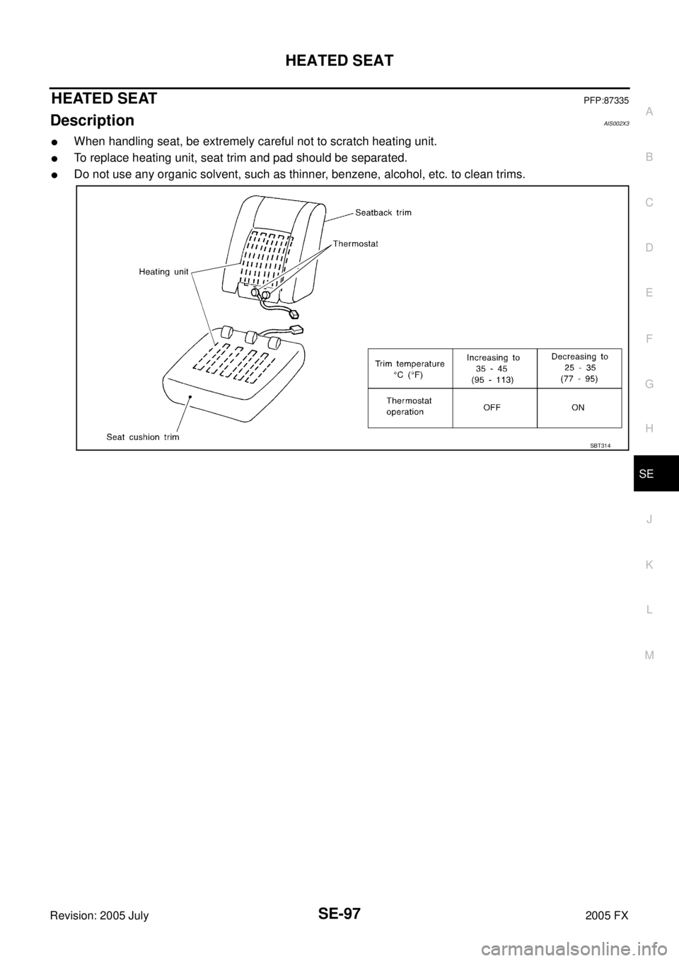
HEATED SEATPFP:87335
DescriptionAIS002X3
�When handling seat, be extremely careful not to scratch heating unit.
�To replace heating unit, seat trim and pad should be separated.
�Do not use any organic solvent, such as thinner, benzene, alcohol, etc. to clean trims.
SBT314
Page 4637 of 4731

TF-4
PRECAUTIONS
Revision: 2005 July 2005 FX
Service Notice or PrecautionsADS000RJ
�Do not reuse transfer fluid, once it has been drained.
�Check the fluid level or replace the fluid only with the vehicle parked on level ground.
�During removal or installation, keep inside of transfer clear of dust or dirt.
�Replace all tires at the same time. Always use tires of the proper size and the same brand and pattern.
Fitting improper size and unusual wear tires applies excessive force to vehicle mechanism and can cause
longitudinal vibration.
�Disassembly should be done in a clean work area, it is preferable to work in dustproof area.
�Before proceeding with disassembly, thoroughly clean the transfer. It is important to prevent the internal
parts from becoming contaminated by dirt or other foreign matter.
�All parts should be carefully cleaned with a general purpose, non-flammable solvent before inspection or
reassembly.
�Check for the correct installation status prior to removal or disassembly. If matching marks are required,
be certain they do not interfere with the function of the parts when applied.
�Check appearance of the disassembled parts for damage, deformation, and unusual wear. Replace them
with a new ones if necessary.
�Gaskets, seals and O-rings should be replaced any time when the transfer is disassembled.
�In principle, tighten bolts or nuts gradually in several steps working diagonally from inside to outside. If
tightening sequence is specified, use it.
�Observe the specified torque when assembling.
�Clean and flush the parts sufficiently and blow-dry them.
�Be careful not to damage sliding surfaces and mating surfaces.
�Clean innerparts with lint-free cloth or towels. Do not use cotton work gloves and rags to prevent adhering
fibers.
Page 4643 of 4731

TF-10
AWD SYSTEM
Revision: 2005 July 2005 FX
AWD SYSTEMPFP:41650
Power Transfer DiagramADS000RV
System DescriptionADS000RW
DESCRIPTION
�Electronic control allows optimal distribution of torque to front/rear wheels to match road conditions.
�Makes possible stable driving, with no wheel spin, on snowy roads or other slippery surfaces.
�On roads which do not require AWD, it contributes to improved fuel economy by driving in conditions close
to rear-wheel drive.
�Sensor inputs determine the vehicle's turning condition, and in response tight cornering/braking are con-
trolled by distributing optimum torque to front wheels.
NOTE:
�When driving, if there is a large difference between front and rear wheel speed which continues for a long
time, fluid temperature of drive system parts becomes too high and AWD warning lamp flashes rapidly.
(When AWD warning lamp flashes, vehicle changes to rear-wheel drive conditions.) Also, optional distri-
bution of torque sometimes becomes rigid before lamp flashes rapidly, but it is not malfunction.
�If AWD warning lamp is flashing rapidly, stop vehicle and allow it to idle for some time. Flashing will stop
and AWD system will be restored.
�When driving, AWD warning lamp may flash slowly if there is a significant difference in diameter of the
tires. At this time, vehicle performance is not fully available and cautious driving is required. (Continues
until engine is turned OFF.)
�If the warning lamp flashes slowly during driving but remains OFF after engine is restarted, the system is
normal. If it again flashes slowly after driving for some time, vehicle must be inspected.
�When the difference of revolution speed between the front and rear wheel mode the shift occasionally
changes to direct 4-wheel driving conditions automatically. This is not malfunction.
SDIA1611E
Page 4674 of 4731
REAR OIL SEAL TF-41
C E F
G H
I
J
K L
M A
B
TF
Revision: 2005 July 2005 FX
REAR OIL SEALPFP:33140
Removal and InstallationADS000RQ
REMOVAL
1. Remove the rear propeller shaft. Refer to PR-7, "REAR PROPELLER SHAFT" .
2. Remove self-lock nut of companion flange using the flange wrench.
3. Put matching mark on the end of the mainshaft. The mark should be in line with the mark on the companion flange.
CAUTION:
For matching mark, use paint. Do not damage mainshaft.
4. Remove the companion flange using a puller. CAUTION:
Be careful not to damage the companion flange.
5. Remove the rear oil seal using a puller. CAUTION:
Be careful not to damage the rear case.
SDIA2454E
SDIA2378E
SDIA1785E
Tool number : KV381054S0 (J-34286)
SDIA1786E
Page 4675 of 4731
TF-42
REAR OIL SEAL
Revision: 2005 July 2005 FX
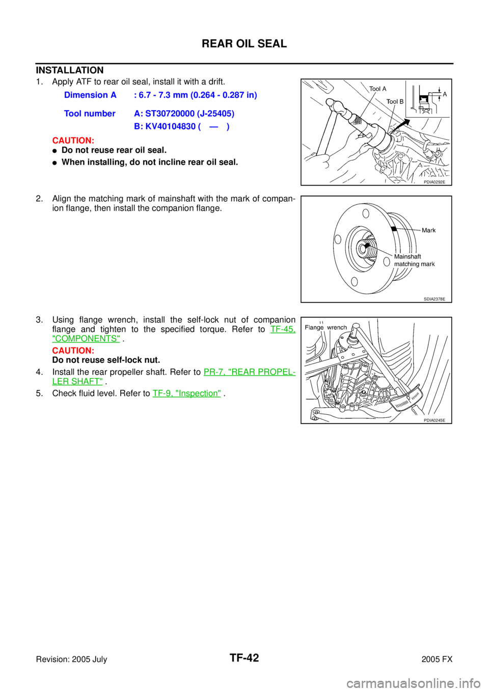
INSTALLATION
1. Apply ATF to rear oil seal, install it with a drift.
CAUTION:
�Do not reuse rear oil seal.
�When installing, do not incline rear oil seal.
2. Align the matching mark of mainshaft with the mark of compan- ion flange, then install the companion flange.
3. Using flange wrench, install the self-lock nut of companion flange and tighten to the specified torque. Refer to TF-45,
"COMPONENTS" .
CAUTION:
Do not reuse self-lock nut.
4. Install the rear propeller shaft. Refer to PR-7, "
REAR PROPEL-
LER SHAFT" .
5. Check fluid level. Refer to TF-9, "
Inspection" .
Dimension A : 6.7 - 7.3 mm (0.264 - 0.287 in)
Tool number A: ST30720000 (J-25405) B: KV40104830 ( — )
PDIA0292E
SDIA2378E
PDIA0245E
 SYSTEM SB-9
C
D E
F
G
I
J
K L
M A
B
SB
Revision: 2005 July 2005 FX
LATCH (LOWER ANCHORS AND TETHER FOR CHILDREN) SYSTEMPFP:75466
Removal and")