Page 3134 of 4731
![INFINITI FX35 2005 Service Manual NOISE, VIBRATION AND HARSHNESS (NVH) TROUBLESHOOTING FAX-9
[AWD]
C E F
G H
I
J
K L
M A
B
FA X
Revision: 2005 July 2005 FX
NOISE, VIBRATION AND HARSHNESS (NVH) TROUBLESHOOTINGPFP:00003
NVH INFINITI FX35 2005 Service Manual NOISE, VIBRATION AND HARSHNESS (NVH) TROUBLESHOOTING FAX-9
[AWD]
C E F
G H
I
J
K L
M A
B
FA X
Revision: 2005 July 2005 FX
NOISE, VIBRATION AND HARSHNESS (NVH) TROUBLESHOOTINGPFP:00003
NVH](/manual-img/42/57020/w960_57020-3133.png)
NOISE, VIBRATION AND HARSHNESS (NVH) TROUBLESHOOTING FAX-9
[AWD]
C E F
G H
I
J
K L
M A
B
FA X
Revision: 2005 July 2005 FX
NOISE, VIBRATION AND HARSHNESS (NVH) TROUBLESHOOTINGPFP:00003
NVH Troubleshooting ChartADS000OK
Use chart below to help you find the cause of the symptom. If necessary, repair or replace these parts.
×: Applicable Reference page
—
FAX-15—
FAX-10—
FAX-10
NVH in FFD section
NVH in FAX and FSU section
Refer to FRONT AXLE in this chart. NVH in WT section
NVH in WT section
Refer to DRIVE SHAFT in this chart. NVH in BR section
NVH in PS section
Possible cause and SUSPECTED PARTS
Excessive joint angle
Joint sliding resistance
Imbalance
Improper installation, looseness
Parts interference
Wheel bearing damage
FRONT DIFFERENTIAL
FRONT AXLE AND FRONT SUSPENSION
FRONT AXLE
TIRES
ROAD WHEEL
DRIVE SHAFT
BRAKES
STEERING
Symptom DRIVE
SHAFT Noise
×× ×××××× ××
Shake ×× ×××××××
FRONT
AXLE Noise
×××× ××××××
Shake ××× ××××××
Vibration ××× ××××
Shimmy ×× ××× ××
Judder ××××××
Poor quality ride or handling ×× ×××
Page 3157 of 4731

FFD-6
NOISE, VIBRATION AND HARSHNESS (NVH) TROUBLESHOOTING
Revision: 2005 July 2005 FX
NOISE, VIBRATION AND HARSHNESS (NVH) TROUBLESHOOTINGPFP:00003
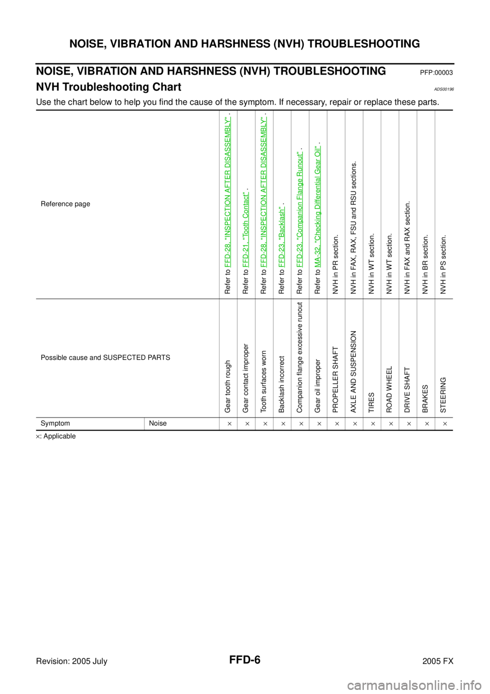
NVH Troubleshooting ChartADS00196
Use the chart below to help you find the cause of the symptom. If necessary, repair or replace these parts.
×: Applicable Reference page
Refer to
FFD-28, "
INSPECTION AFTER DISASSEMBLY
" .
Refer to FFD-21, "
Tooth Contact
" .
Refer to FFD-28, "
INSPECTION AFTER DISASSEMBLY
" .
Refer to FFD-23, "
Backlash
" .
Refer to FFD-23, "
Companion Flange Runout
" .
Refer to MA-32, "
Checking Differential Gear Oil
" .
NVH in PR section.
NVH in FAX, RAX, FSU and RSU sections.
NVH in WT section.
NVH in WT section.
NVH in FAX and RAX section.
NVH in BR section.
NVH in PS section.
Possible cause and SUSPECTED PARTS
Gear tooth rough
Gear contact improper
Tooth surfaces worn
Backlash incorrect
Companion flange excessive runout
Gear oil improper
PROPELLER SHAFT
AXLE AND SUSPENSION
TIRES
ROAD WHEEL
DRIVE SHAFT
BRAKES
STEERING
Symptom Noise ×××××××××××××
Page 3205 of 4731
FSU-2
PRECAUTIONS
Revision: 2005 July 2005 FX
PRECAUTIONSPFP:00001
CautionAES000MZ
�When installing rubber bushings, final tightening must be carried out under unladen conditions with tires
on ground. Oil will shorten the life of rubber bushings. Be sure to wipe off any spilled oil.
�Unladen conditions mean that fuel, engine coolant and lubricant are full. Spare tire, jack, hand tools and
mats are in designated positions.
�After servicing suspension parts, be sure to check wheel alignment.
�Caulking nuts are not reusable. Always use new ones when installing. Since new caulking nuts are pre-
oiled, tighten as they are.
�Avoid burden to front cross bar.
Page 3208 of 4731

NOISE, VIBRATION AND HARSHNESS (NVH) TROUBLESHOOTING FSU-5
C
D
F
G H
I
J
K L
M A
B
FSU
Revision: 2005 July 2005 FX
NOISE, VIBRATION AND HARSHNESS (NVH) TROUBLESHOOTINGPFP:00003
NVH Troubleshooting ChartAES000N2
Use chart below to help you find the cause of the symptom. If necessary, repair or replace these parts.
×: Applicable Reference page
FSU-8FSU-12
—
—
—
FSU-8FSU-6FSU-16
NVH in PR section
NVH in RFD section
NVH in RAX and RSU section
NVH in WT section
NVH in WT section
NVH in RAX section NVH in BR section NVH in PS section
Possible cause and SUSPECTED PARTS
Improper installation, looseness
Strut deformation, damage or deflection
Bushing or mounting deterioration
Parts interference
Spring fatigue
Suspension looseness
Incorrect wheel alignment
Stabilizer bar fatigue
PROPELLER SHAFT (For AWD models)
DIFFERENTIAL (For AWD models)
REAR AXLE AND REAR SUSPENSION
TIRES
ROAD WHEEL
DRIVE SHAFT (For AWD models)
BRAKES
STEERING
Symptom FRONT SUSPENSION Noise
××××× × ××× ×××××
Shake ×××× × × × ×××××
Vibration ××××× × ×× × ×
Shimmy ×××× × ××× ××
Judder ××× ××× ××
Poor quality ride or han-
dling ××××× ×× ×××
Page 3209 of 4731

FSU-6
FRONT SUSPENSION ASSEMBLY
Revision: 2005 July 2005 FX
FRONT SUSPENSION ASSEMBLYPFP:54010
On-Vehicle Inspection and ServiceAES000N3
Make sure the mounting conditions (looseness, back lash) of each component and component statues (wear,
damage) are normal.
INSPECTION OF TRANSVERSE LINK BALL JOINT END PLAY
1. Set front wheels in a straight-ahead position. Do not depress brake pedal.
2. Measure axial end play by installing and moving up/down between transverse link and steering knuckle with an iron pry bar or something similar.
CAUTION:
Be careful not to damage ball joint boot.
STRUT INSPECTION
Check strut for oil leakage, damage and replace if necessary. Refer to FSU-11, "COIL SPRING AND STRUT" .
Wheel Alignment InspectionAES000N4
DESCRIPTION
Measure wheel alignment under unladen conditions.
NOTE:
Unladen conditions mean that fuel, engine coolant, and lubricant are full. Spare tire, jack, hand tools and mats
are designated positions.
PRELIMINARY CHECK
1. Check tires for improper air pressure and wear.
2. Check road wheels for runout.
3. Check wheel bearing axial end play.
4. Check transverse link ball joint axial end play.
5. Check strut operation.
6. Check each mounting part of axle and suspension for looseness and deformation.
7. Check each link, rod and member for cracks, deformation and other damage.
8. Check vehicle posture.
INSPECTION OF CAMBER, CASTER AND KINGPIN INCLINATION ANGLES
�Camber, caster, kingpin inclination angles cannot be adjusted.
�Before inspection, mount front wheels onto turning radius gauge. Mount rear wheels onto a stand that has
same height so vehicle will remain horizontal.
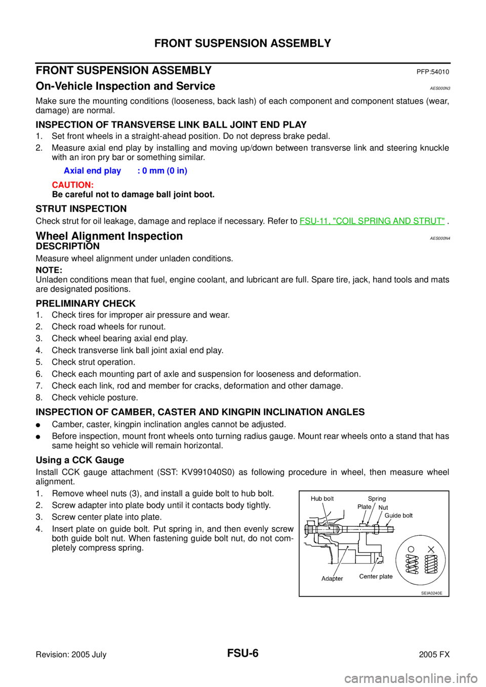
Using a CCK Gauge
Install CCK gauge attachment (SST: KV991040S0) as following procedure in wheel, then measure wheel
alignment.
1. Remove wheel nuts (3), and install a guide bolt to hub bolt.
2. Screw adapter into plate body until it contacts body tightly.
3. Screw center plate into plate.
4. Insert plate on guide bolt. Put spring in, and then evenly screw both guide bolt nut. When fastening guide bolt nut, do not com-
pletely compress spring. Axial end play : 0 mm (0 in)
SEIA0240E
Page 3210 of 4731

FRONT SUSPENSION ASSEMBLY FSU-7
C
D
F
G H
I
J
K L
M A
B
FSU
Revision: 2005 July 2005 FX
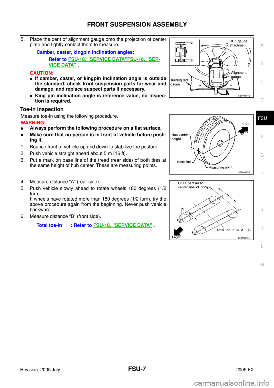
5. Place the dent of alignment gauge onto the projection of center
plate and tightly contact them to measure.
CAUTION:
�If camber, caster, or kingpin inclination angle is outside
the standard, check front suspension parts for wear and
damage, and replace suspect parts if necessary.
�King pin inclination angle is reference value, no inspec-
tion is required.
Toe-In Inspection
Measure toe-in using the following procedure.
WARNING:
�Always perform the following procedure on a flat surface.
�Make sure that no person is in front of vehicle before push-
ing it.
1. Bounce front of vehicle up and down to stabilize the posture.
2. Push vehicle straight ahead about 5 m (16 ft).
3. Put a mark on base line of the tread (rear side) of both tires at the same height of hub center. These are measuring points.
4. Measure distance “A” (rear side).
5. Push vehicle slowly ahead to rotate wheels 180 degrees (1/2 turn).
If wheels have rotated more than 180 degrees (1/2 turn), try the
above procedure again from the beginning. Never push vehicle
backward.
6. Measure distance “B” (front side). Camber, caster, kingpin inclination angles:
Refer to FSU-18, "
SERVICE DATA"FSU-18, "SER-
VICE DATA" .
SEIA0241E
SEIA0362E
Total toe-in : Refer to FSU-18, "SERVICE DATA" .
SEIA0363E
Page 3223 of 4731
GI-2Revision: 2005 July 2005 FX
TIGHTENING TORQUE OF STANDARD BOLTS .
... 47
Tightening Torque Table ...................................... ... 47
RECOMMENDED CHEMICAL PRODUCTS AND
SEALANTS ............................................................ ... 48
Recommended Chemical Products and Sealants ... 48
IDENTIFICATION INFORMATION ......................... ... 49
Model Variation .................................................... ... 49
IDENTIFICATION NUMBER ............................. ... 50 IDENTIFICATION PLATE .................................
... 50
ENGINE SERIAL NUMBER .............................. ... 51
AUTOMATIC TRANSMISSION NUMBER ........ ... 51
Dimensions .......................................................... ... 51
Wheels & Tires ..................................................... ... 51
TERMINOLOGY ..................................................... ... 52
SAE J1930 Terminology List ................................ ... 52
Page 3266 of 4731

TOW TRUCK TOWING GI-45
C
D E
F
G H
I
J
K L
M B
GI
Revision: 2005 July 2005 FX
AWD MODELS
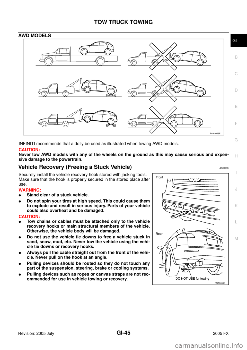
INFINITI recommends that a dolly be used as illustrated when towing AWD models.
CAUTION:
Never tow AWD models with any of the wheels on the ground as this may cause serious and expen-
sive damage to the powertrain.
Vehicle Recovery (Freeing a Stuck Vehicle) AAS000EI
Securely install the vehicle recovery hook stored with jacking tools.
Make sure that the hook is properly secured in the stored place after
use.
WARNING:
�Stand clear of a stuck vehicle.
�Do not spin your tires at high speed. This could cause them
to explode and result in serious injury. Parts of your vehicle
could also overheat and be damaged.
CAUTION:
�Tow chains or cables must be attached only to the vehicle
recovery hooks or main structural members of the vehicle.
Otherwise, the vehicle body will be damaged.
�Do not use the vehicle tie downs to free a vehicle stuck in
sand, snow, mud, etc. Never tow the vehicle using the vehi-
cle tie downs or recovery hooks.
�Always pull the cable straight out from the front of the vehi-
cle. Never pull on the hook at an angle.
�Pulling devices should be routed so they do not touch any
part of the suspension, steering, brake or cooling systems.
�Pulling devices such as ropes or canvas straps are not rec-
ommended for use in vehicle towing or recovery.
PAIA0098E
PAIA0099E