2005 INFINITI FX35 differential
[x] Cancel search: differentialPage 5 of 4731

QUICK REFERENCE CHART M35/M45
REAR WHEEL ALIGNMENT (Unladen*)
ELS0003Y
* : Fuel, engine coolant and engine oil full. Spare tire, jack, hand tools and mats in designated positions.
BRAKEELS0003Z
* : Under force of 490 N (50 kg, 110 lb) with engine running.
REFILL CAPACITIESELS00040
Camber
Degree minute (Decimal degree)Minimum – 1° 18′ (– 1.30°)
Nominal – 0° 48′ (– 0.80°)
Maximum – 0° 18′ (– 0.30°)
Total toe-inDistance ( A – B ) Minimum 2.4 mm (0.094 in)
Nominal 4.7 mm (0.185 in)
Maximum 7.0 mm (0.276 in)
Angle (left plus right )
Degree minute (Degree)Minimum 0° 05′ (0.08°)
Nominal 0° 10′ (0.17°)
Maximum 0° 15′ (0.25°)
Front brake Pad wear limit 2.0 mm (0.079 in)
Rotor repair limit 26.0 mm (1.024 in)
Rear brake Pad wear limit 2.0 mm (0.079 in)
Rotor repair limit 14.0 mm (0.551 in)
Pedal free height 161.5 - 171.5 mm (6.358 - 6.752 in)
Pedal depressed height* More than 80 mm (3.15 in)
UNITLiter US measure
Fuel tank90 23 - 3/4 gal
Coolant ( With reservoir tank )VQ35DE 8.6 9 - 1/8 qt
VK45DE 10.0 10 - 5/8 qt
Engine(VQ35DE)Drain and refill
With oil filter change 4.7 5 qt
Without oil filter change 4.4 4 - 5/8 qt
Dry engine (Overhaul) 5.4 5 - 3/4 qt
Engine(VK45DE)Drain and refill
With oil filter change 6.4 6 - 3/4 qt
Without oil filter change 5.8 6 - 1/8 qt
Dry engine (Overhaul) 7.2 7 - 5/8 qt
Transmission A/T 10.3 10 - 7/8 qt
Transfer1.25 2 - 5/8 pt
Differential carrierFront 0.65 1 - 3/8 pt
Rear 1.4 3 pt
Power steering system 1.0 1 - 1/8 qt
Air conditioning systemCompressor oil 0.18 6.0 fl oz
Refrigerant 0.55 kg 1.21 lb
2005
Page 1114 of 4731

NOISE, VIBRATION AND HARSHNESS (NVH) TROUBLESHOOTING BR-5
C
D E
G H
I
J
K L
M A
B
BR
Revision: 2005 July 2005 FX
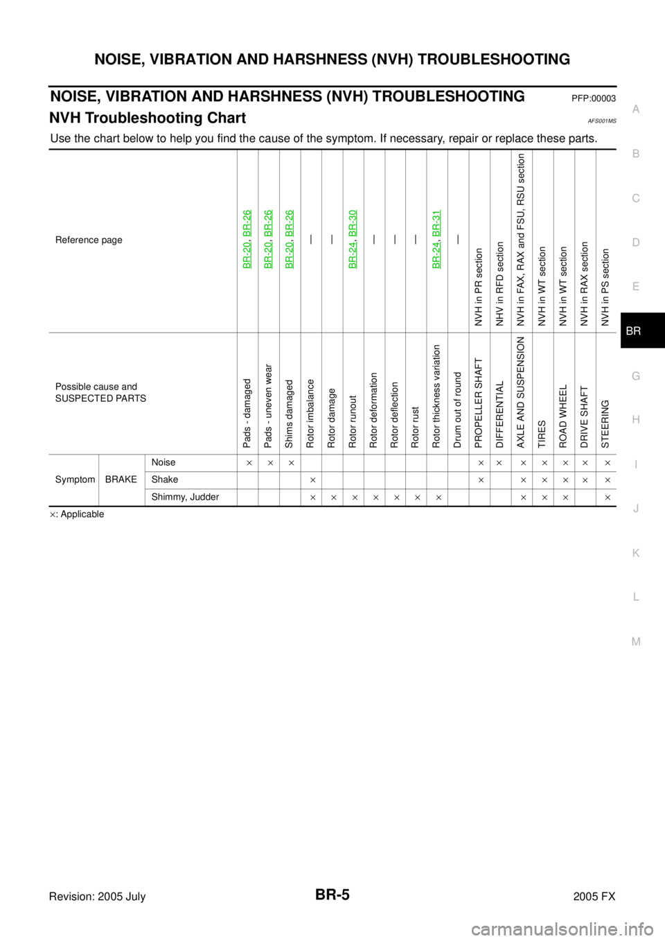
NOISE, VIBRATION AND HARSHNESS (NVH) TROUBLESHOOTINGPFP:00003
NVH Troubleshooting ChartAFS001MS
Use the chart below to help you find the cause of the symptom. If necessary, repair or replace these parts.
×: Applicable
Reference page
BR-20
,
BR-26
BR-20
, BR-26
BR-20
, BR-26—
—
BR-24, BR-30—
—
—
BR-24, BR-31
—
NVH in PR section
NHV in RFD section
NVH in FAX, RAX and FSU, RSU section
NVH in WT section
NVH in WT section
NVH in RAX section
NVH in PS section
Possible cause and
SUSPECTED PARTS
Pads - damaged
Pads - uneven wear
Shims damaged
Rotor imbalance
Rotor damage
Rotor runout
Rotor deformation
Rotor deflection
Rotor rust
Rotor thickness variation
Drum out of round
PROPELLER SHAFT
DIFFERENTIAL
AXLE AND SUSPENSION
TIRES
ROAD WHEEL
DRIVE SHAFT
STEERING
Symptom BRAKE Noise
××× ×× ×××
××
Shake ×××××
××
Shimmy, Judder ××××××× ××× ×
Page 2985 of 4731
![INFINITI FX35 2005 Service Manual EM-150
[VQ35DE]
SERVICE DATA AND SPECIFICATIONS (SDS)
Revision: 2005 July 2005 FX
SERVICE DATA AND SPECIFICATIONS (SDS)PFP:00100
Standard and LimitABS004XK
GENERAL SPECIFICATIONS
Cylinder arrangement INFINITI FX35 2005 Service Manual EM-150
[VQ35DE]
SERVICE DATA AND SPECIFICATIONS (SDS)
Revision: 2005 July 2005 FX
SERVICE DATA AND SPECIFICATIONS (SDS)PFP:00100
Standard and LimitABS004XK
GENERAL SPECIFICATIONS
Cylinder arrangement](/manual-img/42/57020/w960_57020-2984.png)
EM-150
[VQ35DE]
SERVICE DATA AND SPECIFICATIONS (SDS)
Revision: 2005 July 2005 FX
SERVICE DATA AND SPECIFICATIONS (SDS)PFP:00100
Standard and LimitABS004XK
GENERAL SPECIFICATIONS
Cylinder arrangement V-6
Displacement cm
3 (cu in) 3,498 (213.45)
Bore and stroke mm (in) 95.5 x 81.4 (3.760 x 3.205)
Valve arrangement DOHC
Firing order 1-2-3-4-5-6
Number of piston rings Compression 2
Oil 1
Number of main bearings 4
Compression ratio 10.3
Compression pressure
kPa (kg/cm
2 , psi)/300 rpm Standard 1,275 (13.0, 185)
Minimum 981 (10.0, 142)
Differential limit between cylinders 98 (1.0, 14)
Cylinder number
Va l v e t i m i n g
(Intake valve timing control - “OFF”)
Unit: degree
abcde f
240 238 −664 8 52
SEM713A
PBIC0187E
Page 3107 of 4731
![INFINITI FX35 2005 Service Manual EM-272
[VK45DE]
SERVICE DATA AND SPECIFICATIONS (SDS)
Revision: 2005 July 2005 FX
SERVICE DATA AND SPECIFICATIONS (SDS)PFP:00030
Standard and LimitABS006IX
GENERAL SPECIFICATIONS
DRIVE BELTS
INTAKE INFINITI FX35 2005 Service Manual EM-272
[VK45DE]
SERVICE DATA AND SPECIFICATIONS (SDS)
Revision: 2005 July 2005 FX
SERVICE DATA AND SPECIFICATIONS (SDS)PFP:00030
Standard and LimitABS006IX
GENERAL SPECIFICATIONS
DRIVE BELTS
INTAKE](/manual-img/42/57020/w960_57020-3106.png)
EM-272
[VK45DE]
SERVICE DATA AND SPECIFICATIONS (SDS)
Revision: 2005 July 2005 FX
SERVICE DATA AND SPECIFICATIONS (SDS)PFP:00030
Standard and LimitABS006IX
GENERAL SPECIFICATIONS
DRIVE BELTS
INTAKE MANIFOLD AND EXHAUST MANIFOLD
Unit: mm (in)
Cylinder arrangement
V-8
Displacement cm
3 (cu in) 4,494 (274.22)
Bore and stroke mm (in) 93 x 82.7 (3.66 x 3.256)
Valve arrangement DOHC
Firing order 1-8-7-3-6-5-4-2
Number of piston rings Compression 2
Oil 1
Number of main bearings 5
Compression ratio 10.5
Compression pressure
kPa (kg/cm
2 , psi)/300 rpm Standard 1,320 (13.5, 191)
Minimum 1,130 (11.5, 164)
Differential limit
between cylinders 98 (1.0, 14)
Cylinder number
Va l v e t i m i n g Unit: degree
abcde f
228240060048
SEM957C
PBIC0187E
Tension of drive belts Auto adjustment by auto tensioner
Items Limit
Surface distortion Intake manifold (upper) 0.1 (0.004)
Intake manifold (lower) 0.1 (0.004)
Exhaust manifold 0.3 (0.012)
Page 3134 of 4731
![INFINITI FX35 2005 Service Manual NOISE, VIBRATION AND HARSHNESS (NVH) TROUBLESHOOTING FAX-9
[AWD]
C E F
G H
I
J
K L
M A
B
FA X
Revision: 2005 July 2005 FX
NOISE, VIBRATION AND HARSHNESS (NVH) TROUBLESHOOTINGPFP:00003
NVH INFINITI FX35 2005 Service Manual NOISE, VIBRATION AND HARSHNESS (NVH) TROUBLESHOOTING FAX-9
[AWD]
C E F
G H
I
J
K L
M A
B
FA X
Revision: 2005 July 2005 FX
NOISE, VIBRATION AND HARSHNESS (NVH) TROUBLESHOOTINGPFP:00003
NVH](/manual-img/42/57020/w960_57020-3133.png)
NOISE, VIBRATION AND HARSHNESS (NVH) TROUBLESHOOTING FAX-9
[AWD]
C E F
G H
I
J
K L
M A
B
FA X
Revision: 2005 July 2005 FX
NOISE, VIBRATION AND HARSHNESS (NVH) TROUBLESHOOTINGPFP:00003
NVH Troubleshooting ChartADS000OK
Use chart below to help you find the cause of the symptom. If necessary, repair or replace these parts.
×: Applicable Reference page
—
FAX-15—
FAX-10—
FAX-10
NVH in FFD section
NVH in FAX and FSU section
Refer to FRONT AXLE in this chart. NVH in WT section
NVH in WT section
Refer to DRIVE SHAFT in this chart. NVH in BR section
NVH in PS section
Possible cause and SUSPECTED PARTS
Excessive joint angle
Joint sliding resistance
Imbalance
Improper installation, looseness
Parts interference
Wheel bearing damage
FRONT DIFFERENTIAL
FRONT AXLE AND FRONT SUSPENSION
FRONT AXLE
TIRES
ROAD WHEEL
DRIVE SHAFT
BRAKES
STEERING
Symptom DRIVE
SHAFT Noise
×× ×××××× ××
Shake ×× ×××××××
FRONT
AXLE Noise
×××× ××××××
Shake ××× ××××××
Vibration ××× ××××
Shimmy ×× ××× ××
Judder ××××××
Poor quality ride or handling ×× ×××
Page 3152 of 4731

FFD-1
FRONT FINAL DRIVE
D DRIVELINE/AXLE
CONTENTS
C E F
G H
I
J
K L
M
SECTION FFD
A
B
FFD
Revision: 2005 July 2005 FX
FRONT FINAL DRIVE
PRECAUTIONS .......................................................... 2
Service Notice or Precautions ............................. ..... 2
PREPARATION ...................................................... ..... 3
Special Service Tools .......................................... ..... 3
Commercial Service Tools ................................... ..... 5
NOISE, VIBRATION AND HARSHNESS (NVH)
TROUBLESHOOTING ........................................... ..... 6
NVH Troubleshooting Chart ................................ ..... 6
DESCRIPTION ....................................................... ..... 7
Cross-Sectional View .......................................... ..... 7
DIFFERENTIAL GEAR OIL ................................... ..... 8
Changing Differential Gear Oil ............................ ..... 8
DRAINING ........................................................ ..... 8
FILLING ............................................................ ..... 8
Checking Differential Gear Oil ............................. ..... 8
OIL LEAKAGE AND OIL LEVEL ...................... ..... 8
FRONT OIL SEAL ................................................. ..... 9
Removal and Installation ..................................... ..... 9
REMOVAL ........................................................ ..... 9
INSTALLATION ................................................ ... 10
SIDE OIL SEAL ..................................................... ....11
Removal and Installation ..................................... .... 11
REMOVAL ........................................................ .... 11
INSTALLATION ................................................ .... 11
FRONT FINAL DRIVE ASSEMBLY ....................... ... 12
Removal and Installation (VQ35DE Models) ....... ... 12 COMPONENTS ................................................
... 12
REMOVAL ........................................................ ... 12
INSTALLATION ................................................ ... 12
Removal and Installation (VK45DE Models) ....... ... 14
COMPONENTS ................................................ ... 14
REMOVAL ........................................................ ... 14
INSTALLATION ................................................ ... 14
Disassembly and Assembly ................................. ... 16
COMPONENTS (VQ35DE MODELS) .............. ... 16
COMPONENTS (VK45DE MODELS) .............. ... 18
ASSEMBLY INSPECTION AND ADJUSTMENT ... 20
DISASSEMBLY ................................................ ... 24
INSPECTION AFTER DISASSEMBLY ............. ... 28
ADJUSTMENT AND SELECTION OF ADJUST-
ING WASHERS (SHIMS) ................................. ... 29
ASSEMBLY ...................................................... ... 32
SERVICE DATA AND SPECIFICATIONS (SDS) ... ... 39
General Specifications ......................................... ... 39
Inspection and Adjustment .................................. ... 39
DRIVE GEAR RUNOUT ................................... ... 39
DIFFERENTIAL SIDE GEAR CLEARANCE .... ... 39
PRELOAD TORQUE ........................................ ... 39
BACKLASH ...................................................... ... 39
COMPANION FLANGE RUNOUT .................... ... 39
SELECTIVE PARTS ......................................... ... 39
Page 3155 of 4731

FFD-4
PREPARATION
Revision: 2005 July 2005 FX
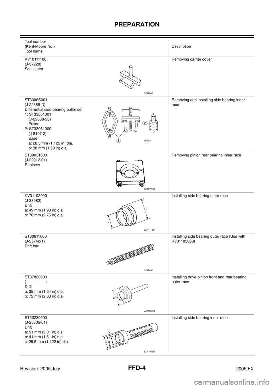
K V 1 0 1111 0 0
(J-37228)
Seal cutter Removing carrier cover
ST3306S001
(J-22888-D)
Differential side bearing puller set
1: ST33051001 (J-22888-20)
Puller
2: ST33061000 (J-8107-2)
Base
a: 28.5 mm (1.122 in) dia.
b: 38 mm (1.50 in) dia. Removing and installing side bearing inner
race
ST30031000
(J-22912-01)
Replacer Removing pinion rear bearing inner race
KV31103000
(J-38982)
Drift
a: 49 mm (1.93 in) dia.
b: 70 mm (2.76 in) dia. Installing side bearing outer race
ST30611000
(J-25742-1)
Drift bar Installing side bearing outer race (Use with
KV31103000)
ST37820000
(—)
Drift
a: 39 mm (1.54 in) dia.
b: 72 mm (2.83 in) dia. Installing drive pinion front and rear bearing
outer race
ST33230000
(J-25805-01)
Drift
a: 51 mm (2.01 in) dia.
b: 41 mm (1.61 in) dia.
c: 28.5 mm (1.122 in) dia. Installing side bearing inner race
Tool number
(Kent-Moore No.)
Tool name Description
S-NT046
NT072
ZZA0700D
ZZA1113D
S-NT090
ZZA0836D
ZZA1046D
Page 3157 of 4731

FFD-6
NOISE, VIBRATION AND HARSHNESS (NVH) TROUBLESHOOTING
Revision: 2005 July 2005 FX
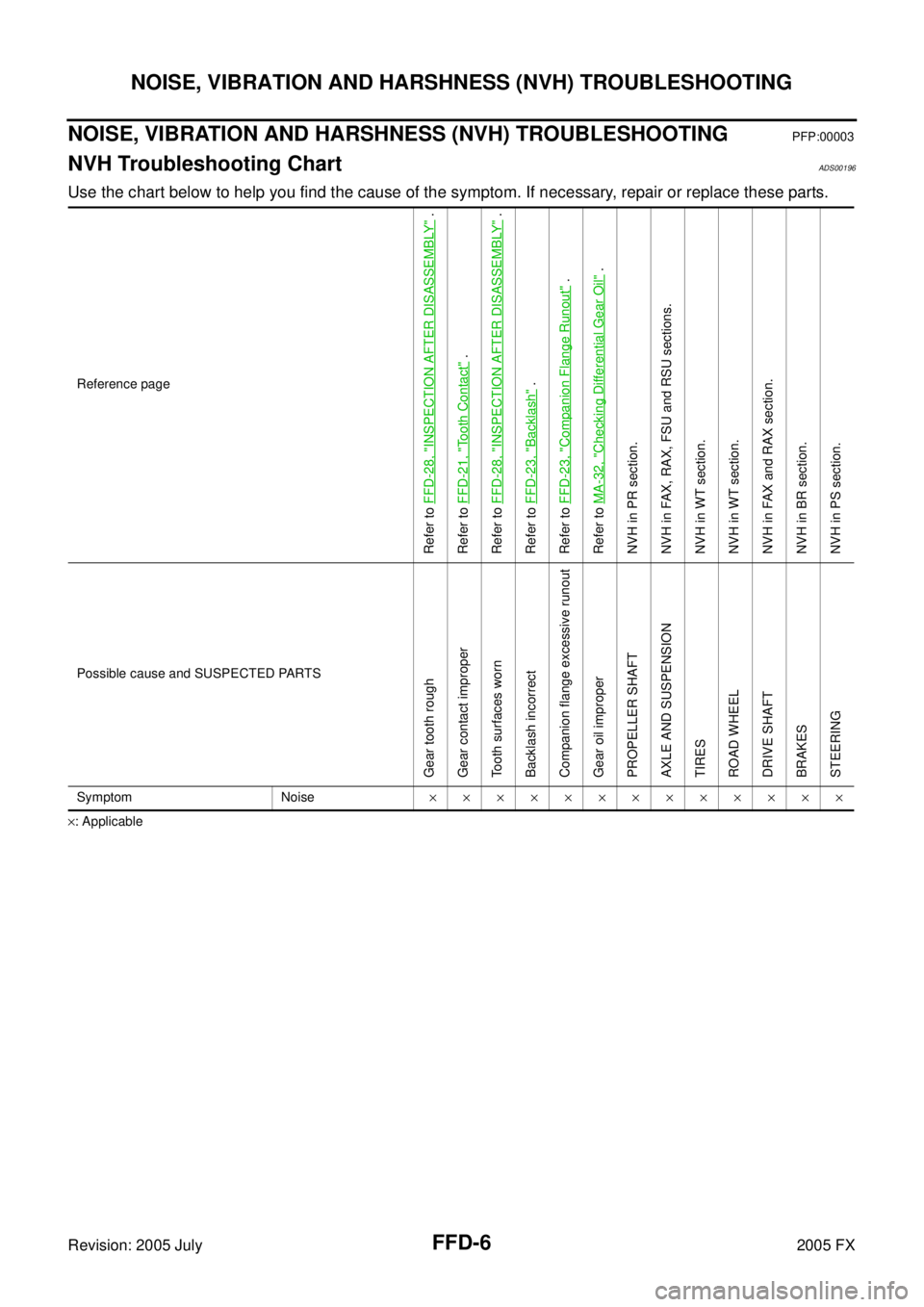
NOISE, VIBRATION AND HARSHNESS (NVH) TROUBLESHOOTINGPFP:00003
NVH Troubleshooting ChartADS00196
Use the chart below to help you find the cause of the symptom. If necessary, repair or replace these parts.
×: Applicable Reference page
Refer to
FFD-28, "
INSPECTION AFTER DISASSEMBLY
" .
Refer to FFD-21, "
Tooth Contact
" .
Refer to FFD-28, "
INSPECTION AFTER DISASSEMBLY
" .
Refer to FFD-23, "
Backlash
" .
Refer to FFD-23, "
Companion Flange Runout
" .
Refer to MA-32, "
Checking Differential Gear Oil
" .
NVH in PR section.
NVH in FAX, RAX, FSU and RSU sections.
NVH in WT section.
NVH in WT section.
NVH in FAX and RAX section.
NVH in BR section.
NVH in PS section.
Possible cause and SUSPECTED PARTS
Gear tooth rough
Gear contact improper
Tooth surfaces worn
Backlash incorrect
Companion flange excessive runout
Gear oil improper
PROPELLER SHAFT
AXLE AND SUSPENSION
TIRES
ROAD WHEEL
DRIVE SHAFT
BRAKES
STEERING
Symptom Noise ×××××××××××××