Page 3174 of 4731
, or near the
heel (heel contact), thicken p")
FRONT FINAL DRIVE ASSEMBLY FFD-23
C E F
G H
I
J
K L
M A
B
FFD
Revision: 2005 July 2005 FX
�If the tooth contact is near the face (face contact), or near the
heel (heel contact), thicken pinon height adjusting washers to
move drive pinion closer to drive gear.
Refer to FFD-40, "
Pinion Height Adjusting Washer" .
�If the tooth contact is near the flank (flank contact), or near the
toe (toe contact), thin pinion height adjusting washers to move
drive pinion farther from drive gear.
Refer to FFD-40, "
Pinion Height Adjusting Washer" .
Backlash
1. Remove carrier cover. Refer to FFD-24, "Differential Assembly" .
2. Fit a dial indicator to the drive gear face to measure the back- lash.
�If the backlash is outside of the specified value, change the
thickness of side bearing adjusting washer.
Companion Flange Runout
1. Fit a dial indicator onto the companion flange face (inner side of
the propeller shaft mounting bolt holes).
2. Rotate companion flange to check for runout.
3. Fit a test indicator to the inner side of companion flange (socket diameter).
4. Rotate companion flange to check for runout.
5. If the runout value is outside the runout limit, follow the proce- dure below to adjust.
a. Check for runout while changing the phase between companion flange and drive pinion by 90 ° step, and
search for the position where the runout is the minimum.
b. If the runout value is still outside of the limit after the phase has been changed, possible cause will be an assembly malfunction of drive pinion and pinion bearing and malfunction of pinion bearing. Check for
these items and repair if necessary.
PDIA0440E
PDIA0441E
Backlash: 0.10 - 0.15 mm (0.0039 - 0.0059 in)
When the backlash is large: Decrease side bearing adjusting washer thickness.
Refer to FFD-40, "
Side Bearing Adjusting Washer" .
When the backlash is small: Increase side bearing adjusting washer thickness.
Refer to FFD-40, "
Side Bearing Adjusting Washer" .
SDIA0009J
Runout limit: 0.18 mm (0.0070 in) or less
Runout limit: 0.13 mm (0.0051 in) or less
PDIA0646E
Page 3175 of 4731
FFD-24
FRONT FINAL DRIVE ASSEMBLY
Revision: 2005 July 2005 FX
c. If the runout value is still outside of the limit after the check and repair, replace companion flange.
DISASSEMBLY
Side Shaft Assembly
1. Hold extension tube retainer with puller, then press out side shaft using a press.
2. Remove side shaft oil seal from extension tube retainer with a flat- blade screwdriver.
3. Remove side shaft bearing from extension tube retainer.
4. Remove O-ring from extension tube retainer.
5. Remove dust sealed from side shaft.
Differential Assembly
1. Drain gear oil, if necessary.
2. Remove carrier cover mounting bolts.
3. Remove carrier cover to insert the seal cutter between gear car- rier and carrier cover.
CAUTION:
�Be careful not to damage the mating surface.
�Do not insert flat-bladed screwdriver, this way damage
the mating surface.
4. Remove side retainer mounting bolts.
SDIA1628E
PDIA0664E
Tool number : KV10111100 (J-37228)
PDIA0668E
PDIA0669E
Page 3176 of 4731
FRONT FINAL DRIVE ASSEMBLY FFD-25
C E F
G H
I
J
K L
M A
B
FFD
Revision: 2005 July 2005 FX
5. Remove side retainer.
6. Remove side bearing adjusting shim.
7. Remove O-ring from side retainer.
8. Remove differential case assembly from gear carrier.
9. Remove side oil seal (right side) from side retainer.
10. Remove side bearing outer race with puller.
11. Remove O-ring from gear carrier.
12. Remove side oil seal (left side) from gear carrier.
13. Remove side bearing outer race with puller.
PDIA0670E
PDIA0671E
PDIA0672E
Tool number : KV381054S0 (J-34286)
PDIA0673E
Tool number : KV381054S0 (J-34286)
PDIA0674E
Page 3177 of 4731
FFD-26
FRONT FINAL DRIVE ASSEMBLY
Revision: 2005 July 2005 FX
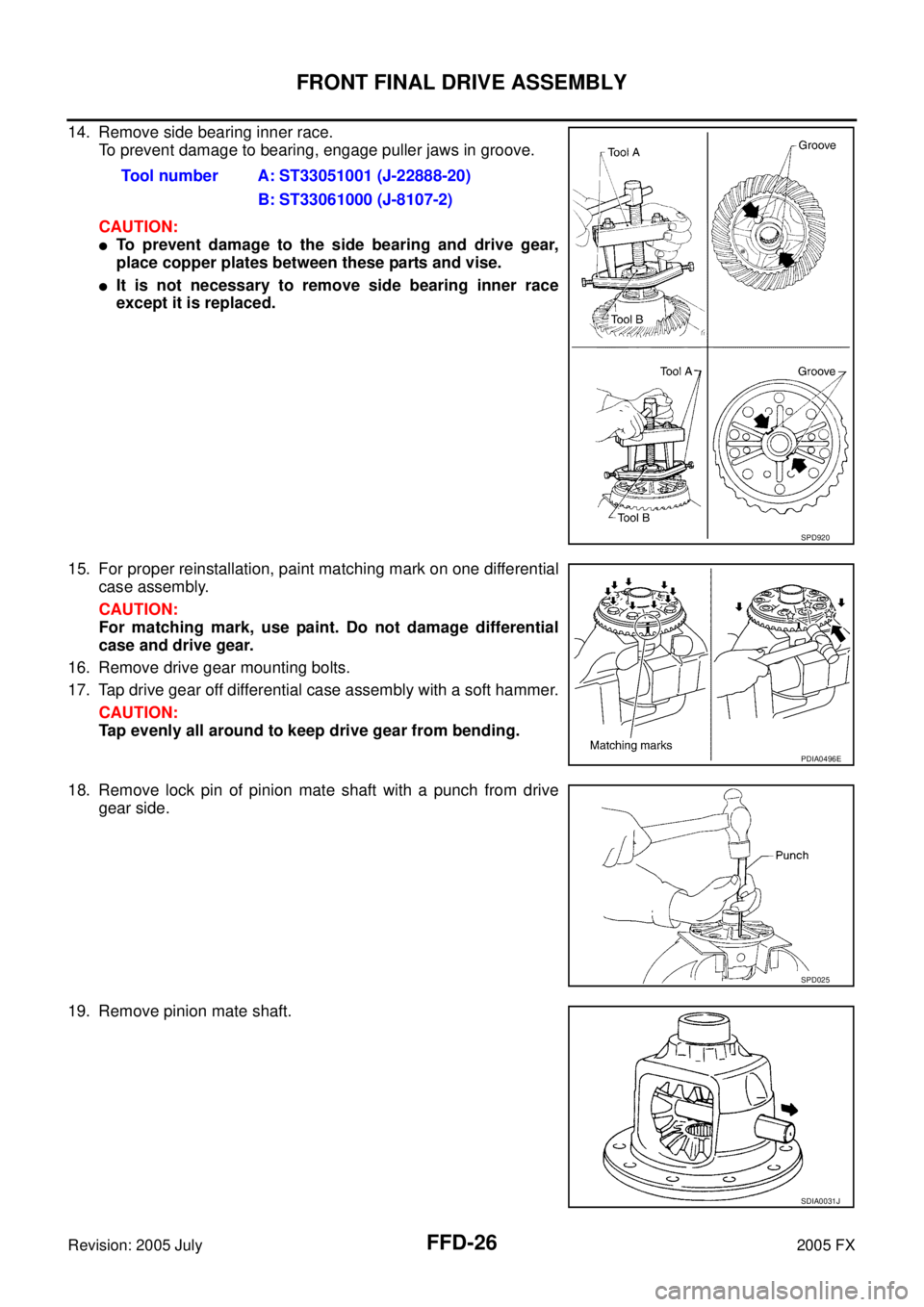
14. Remove side bearing inner race.
To prevent damage to bearing, engage puller jaws in groove.
CAUTION:
�To prevent damage to the side bearing and drive gear,
place copper plates between these parts and vise.
�It is not necessary to remove side bearing inner race
except it is replaced.
15. For proper reinstallation, paint matching mark on one differential case assembly.
CAUTION:
For matching mark, use paint. Do not damage differential
case and drive gear.
16. Remove drive gear mounting bolts.
17. Tap drive gear off differential case assembly with a soft hammer. CAUTION:
Tap evenly all around to keep drive gear from bending.
18. Remove lock pin of pinion mate shaft with a punch from drive gear side.
19. Remove pinion mate shaft. Tool number A: ST33051001 (J-22888-20)
B: ST33061000 (J-8107-2)
SPD920
PDIA0496E
SPD025
SDIA0031J
Page 3178 of 4731
FRONT FINAL DRIVE ASSEMBLY FFD-27
C E F
G H
I
J
K L
M A
B
FFD
Revision: 2005 July 2005 FX
20. Turn pinion mate gear, then remove pinion mate gears, pinion
mate thrust washers, side gears and side gear thrust washers
from differential case.
Drive Pinion Assembly
1. Remove differential assembly. Refer to FFD-24, "Differential Assembly" .
2. Remove drive pinion lock nut with a flange wrench.
3. Put matching mark on the end of drive pinion. The matching mark should be in line with the matching mark A on companion
flange.
CAUTION:
For matching mark, use paint. Do not damage companion
flange and drive pinion.
NOTE:
The matching mark A on the final drive companion flange indi-
cates the maximum vertical runout position.
When replacing companion flange, matching mark is not neces-
sary.
4. Remove companion flange using the suitable puller.
SDIA0032J
PDIA0741E
PDIA0675E
SDIA1132E
Page 3179 of 4731

FFD-28
FRONT FINAL DRIVE ASSEMBLY
Revision: 2005 July 2005 FX
5. Press drive pinion assembly out of gear carrier.
CAUTION:
Do not drop drive pinion assembly.
6. Remove front oil seal.
7. Remove pinion front bearing inner race.
8. Remove drive pinion bearing adjusting washer and drive pinion adjusting washer.
9. Remove pinion rear bearing inner race and drive pinion height adjusting washer with replacer.
10. Tap pinion front/rear bearing outer races uniformly a brass rod or equivalent to removed.
CAUTION:
Be careful not to damage gear carrier.
INSPECTION AFTER DISASSEMBLY
Clean up the disassembled parts. Then, inspect if the parts are worn or damaged. If so, follow the measures
below.
PDIA0676E
Tool number : ST30031000 (J-22912-01)
S-PD179
PDIA0677E
Content Conditions and Measures
Hypoid gear
�If the gear teeth do not mesh or line-up correctly, determine the cause and adjust or replace as nec-
essary.
�If the gears are worn, cracked, damaged, pitted or chipped (by friction) noticeably, replace with new
drive gear and drive pinion as a set.
Bearing
�If any chipped (by friction), pitted, worn, rusted or scratched mark, or unusual noise from the bearing
is observed, replace as a bearing assembly (as a new set).
Side gear and Pinion mate
gear
�If any cracks or damage on the surface of the tooth is found, replace.
�If any worn or chipped mark on the contact sides of the thrust washer is found, replace.
Side gear thrust washer and
pinion mate thrust washer
�If it is chipped (by friction), damaged, or unusually worn, replace.
Oil seal
�Whenever disassembled, replace.
�If wear, deterioration of adherence (sealing force lips), or damage is detected on the lips, replace
them.
Differential case
�If any wear or crack on the contact sides of the differential case is found, replace.
Companion flange
�If any chipped mark (about 0.1 mm, 0.004 in) or other damage on the contact sides of the lips of the
companion flange is found, replace.
Page 3180 of 4731

Differential Side Gear Clearance
�Assemble")
FRONT FINAL DRIVE ASSEMBLY FFD-29
C E F
G H
I
J
K L
M A
B
FFD
Revision: 2005 July 2005 FX
ADJUSTMENT AND SELECTION OF ADJUSTING WASHERS (SHIMS)
Differential Side Gear Clearance
�Assemble the differential parts if they are disassembled. Refer to FFD-34, "Differential Assembly" .
1. Place differential case straight up so that side gear to be mea- sured comes upward.
2. Using feeler gauge, measure the clearance between side gear back and differential case at 3 different points, while rotating
side gear. Average the 3 readings, and then measure the clear-
ance of the other side as well.
CAUTION:
To prevent side gear from tilting, insert feeler gauges with
the same thickness from both sides.
3. If the back clearance is outside the specification, use a thicker/ thinner side gear thrust washer to adjust. Refer to FFD-39, "
Side
Gear Thrust Washer" .
CAUTION:
Select a side gear thrust washer for right and left individu-
ally.
Side Bearing Preload
1. Make sure all parts are clean. Also, make sure the bearings are well lubricated with gear oil.
2. Press-fit side bearing outer race into side retainer with tool.
CAUTION:
�At first, using a hammer, tap bearing outer race until it
becomes flat to side retainer.
�Do not reuse side bearing outer race.
PDIA0460E
Side gear back clearance specification:
0.2 mm (0.008 in) or less.
(Each gear should rotate smoothly without excessive
resistance during differential motion.)
When the back clearance is large: Use a thicker thrust washer.
When the back clearance is small: Use a thinner thrust washer.
PDIA0576E
Tool number A: KV31103000 ( — ) B: ST30611000 (J-25742-1)
PDIA0679E
Page 3181 of 4731

FFD-30
FRONT FINAL DRIVE ASSEMBLY
Revision: 2005 July 2005 FX
3. Press-fit side bearing outer race into gear carrier with tool.
CAUTION:
�At first, using a hammer, tap bearing outer race until it
becomes flat to gear carrier.
�Do not reuse side bearing outer race.
4. Place the differential case assembly into gear carrier.
5. Install side bearing adjusting shim before disassembling or shim which thickness is the same as the one before disassembling.
6. Install side retainer assembly to gear carrier.
CAUTION:
Do not install O-ring.
7. Install side retainer mounting bolts to the specified torque. Refer to FFD-16, "
COMPONENTS (VQ35DE MODELS)" , FFD-18,
"COMPONENTS (VK45DE MODELS)" .
8. Measure the turning torque of the gear carrier at the drive gear mounting bolts with a spring gauge. Tool number A: KV31103000 ( — )
B: ST30611000 (J-25742-1)
PDIA0824E
PDIA0671E
PDIA0678E
PDIA0669E
Tool number : — (J-8129)
Specification:
0.78 - 1.08 N (0.08 - 0.11 kg, 0.57 - 0.80 lb) of pulling
force at the drive gear bolt
SPD194A