Page 4285 of 4731
PS-10
STEERING WHEEL
Revision: 2005 July 2005 FX
STEERING WHEELPFP:48430
On-Vehicle Inspection and ServiceAGS000GW
CHECKING CONDITION OF INSTALLATION
�Check installation condition of steering gear assembly, front suspension, axle and steering column.
�Check if movement exists when steering wheel is moved up and down, to the left and right and to the axial
direction.
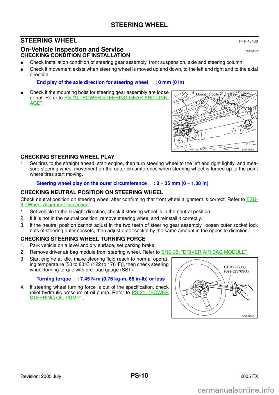
�Check if the mounting bolts for steering gear assembly are loose
or not. Refer to PS-19, "
POWER STEERING GEAR AND LINK-
AGE" .
CHECKING STEERING WHEEL PLAY
1. Set tires to the straight ahead, start engine, then turn steering wheel to the left and right lightly, and mea-
sure steering wheel movement on the outer circumference when steering wheel is turned up to the point
where tires start moving.
CHECKING NEUTRAL POSITION ON STEERING WHEEL
Check neutral position on steering wheel after confirming that front wheel alignment is correct. Refer to FSU-
6, "Wheel Alignment Inspection" .
1. Set vehicle to the straight direction, check if steering wheel is in the neutral position.
2. If it is not in the neutral position, remove steering wheel and reinstall it correctly.
3. If the neutral position cannot adjust in the two teeth of steering gear assembly, loosen outer socket lock nuts of steering outer sockets, then adjust outer socket by the same amount in the opposite direction.
CHECKING STEERING WHEEL TURNING FORCE
1. Park vehicle on a level and dry surface, set parking brake.
2. Remove driver air bag module from steering wheel. Refer to SRS-35, "
DRIVER AIR BAG MODULE" .
3. Start engine at idle, make steering fluid reach to normal operat- ing temperature [50 to 80 °C (122 to 176 °F)], then check steering
wheel turning torque with pre-load gauge (SST).
4. If steering wheel turning force is out of the specification, check relief hydraulic pressure of oil pump. Refer to PS-31, "
POWER
STEERING OIL PUMP" .
End play of the axle direction for steering wheel : 0 mm (0 in)
SGIA0546E
Steering wheel play on the outer circumference : 0
− 35 mm (0 − 1.38 in)
Turning torque : 7.45 N·m (0.76 kg-m, 66 in-lb) or less
SGIA0459E
Page 4294 of 4731
POWER STEERING GEAR AND LINKAGE PS-19
C
D E
F
H I
J
K L
M A
B
PS
Revision: 2005 July 2005 FX
POWER STEERING GEAR AND LINKAGEPFP:49001
Removal and InstallationAGS000H0
CAUTION:
Spiral cable may snap due to steering operation if steering column is separated from steering gear
assembly. Therefore fix steering wheel with a string to avoid turns.
REMOVAL
1. Set wheels in the straight-ahead position.
2. Remove tires from vehicle with power tool.
3. Remove undercover with power tool.
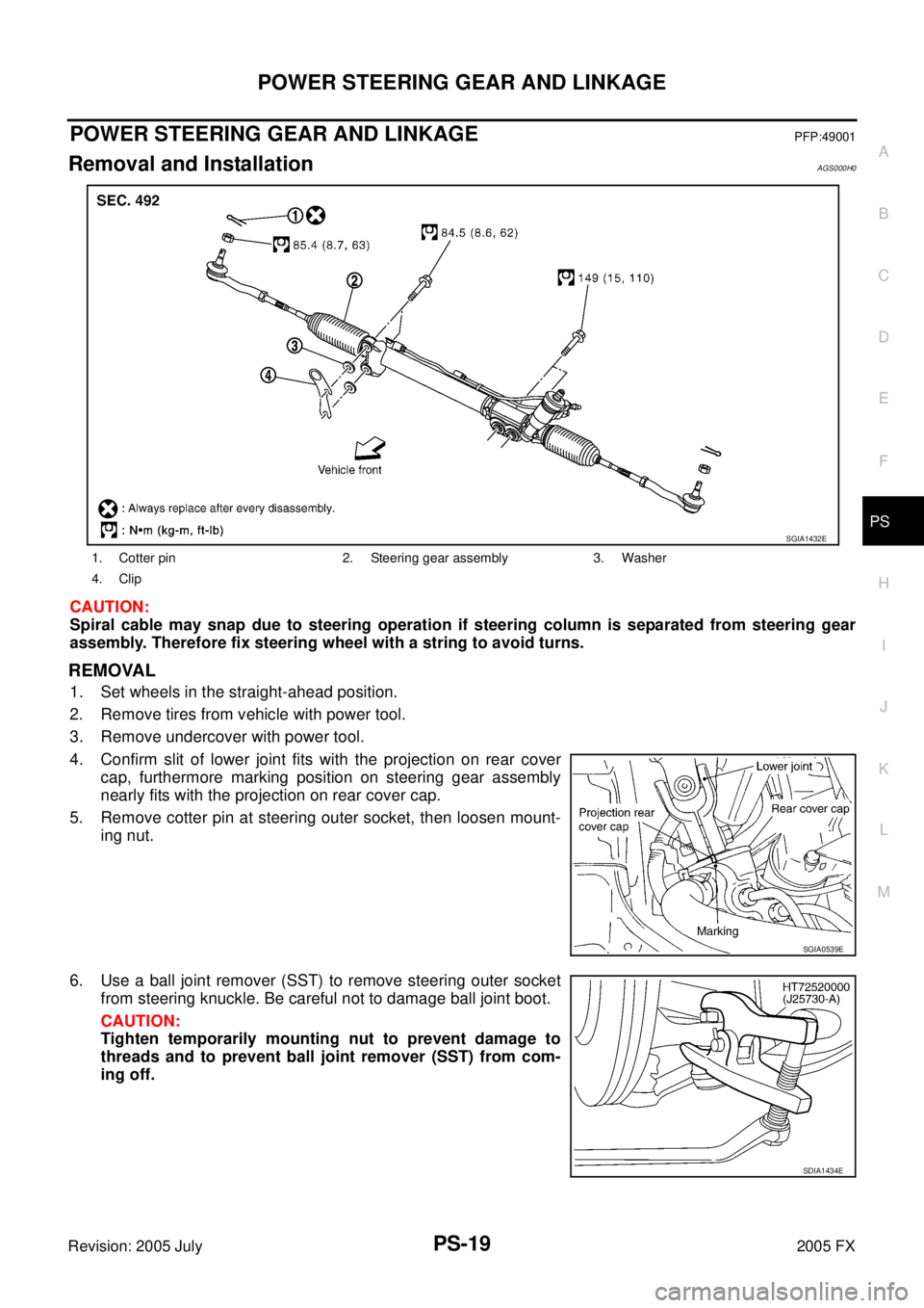
4. Confirm slit of lower joint fits with the projection on rear cover cap, furthermore marking position on steering gear assembly
nearly fits with the projection on rear cover cap.
5. Remove cotter pin at steering outer socket, then loosen mount- ing nut.
6. Use a ball joint remover (SST) to remove steering outer socket from steering knuckle. Be careful not to damage ball joint boot.
CAUTION:
Tighten temporarily mounting nut to prevent damage to
threads and to prevent ball joint remover (SST) from com-
ing off.
1. Cotter pin 2. Steering gear assembly 3. Washer
4. Clip
SGIA1432E
SGIA0539E
SDIA1434E
Page 4327 of 4731

RAX-4
NOISE, VIBRATION AND HARSHNESS (NVH) TROUBLESHOOTING
Revision: 2005 July 2005 FX
NOISE, VIBRATION AND HARSHNESS (NVH) TROUBLESHOOTINGPFP:00003
NVH Troubleshooting ChartADS000C3
Use chart below to help you find the cause of the symptom. If necessary, repair or replace these parts.
×: Applicable Reference page
—
RAX-9—
RAX-5—
NVH in PR section
NVH in RFD section
NVH in FAX and FSU section
Refer to REAR AXLE in this chart. NVH in WT section
NVH in WT section
Refer to DRIVE SHAFT in this chart. NVH in BR section
NVH in PS section
Possible cause and SUSPECTED PARTS
Excessive joint angle
Joint sliding resistance
Imbalance
Improper installation, looseness
Parts interference
PROPELLER SHAFT
DIFFERENTIAL
FRONT AXLE AND FRONT SUSPENSION
REAR AXLE
TIRES
ROAD WHEEL
DRIVE SHAFT
BRAKES
STEERING
Symptom DRIVE
SHAFT Noise
×× ×××××× ××
Shake ×× ×××××××
REAR
AXLE Noise
×× ××× ×××××
Shake ×××××××××
Vibration ×××××××
Shimmy ×× ×××××
Judder × × ×× ××
Poor quality ride or handling ×× × ××
Page 4329 of 4731
RAX-6
WHEEL HUB
Revision: 2005 July 2005 FX
10. Loosen fixing bolts and nuts of front lower link, radius rod, and rear lower link in side of suspension mem-
ber.
11. Set jack under rear lower link. Then remove fixing bolt in front lower link side of shock absorber with power tool.
12. Remove bolt and nut in axle side of rear lower link with power tool. Then remove coil spring. Refer to RSU-15, "
REAR LOWER LINK & COIL SPRING" .
13. Remove fixing bolts and nuts in axle side of front lower link, radius rod with power tool.
14. Remove suspension arm and cotter pin at axle, then loosen mounting nut.
15. Use a ball joint remover (suitable tool) to remove suspension arm from axle. Be careful not to damage ball joint boot.
CAUTION:
Tighten temporarily mounting nut to prevent damage to threads and to prevent ball joint remover
(suitable tool) from coming off.
16. Remove axle from vehicle.
INSPECTION AFTER REMOVAL
Ball Joint Inspection
Check for boot breakage, axial looseness, and torque of suspension arm ball joint. Refer to RSU-11,
"INSPECTION AFTER REMOVAL" .
INSTALLATION
�Refer to RAX-5, "Removal and Installation" for tightening torque. Install in the reverse order of removal.
NOTE:
Refer to component parts location and do not reuse non-reusable parts.
�Perform final tightening of installation position of suspension links (rubber bushing) under unladen condi-
tions with tires on level ground, Check wheel alignment. Refer to RSU-5, "
Wheel Alignment Inspection" .
�After adjusting wheel alignment, adjust neutral position of steering angle sensor. Refer to BRC-6, "Adjust-
ment of Steering Angle Sensor Neutral Position" .
Disassembly and AssemblyADS000C6
DISASSEMBLY
Wheel Bearing
CAUTION:
Do not disassemble if wheel bearing has no trouble.
1. Remove wheel bearing fixing bolts and anchor block fixing nuts, and remove wheel hub and bearing assembly, back plate and anchor block from axle.
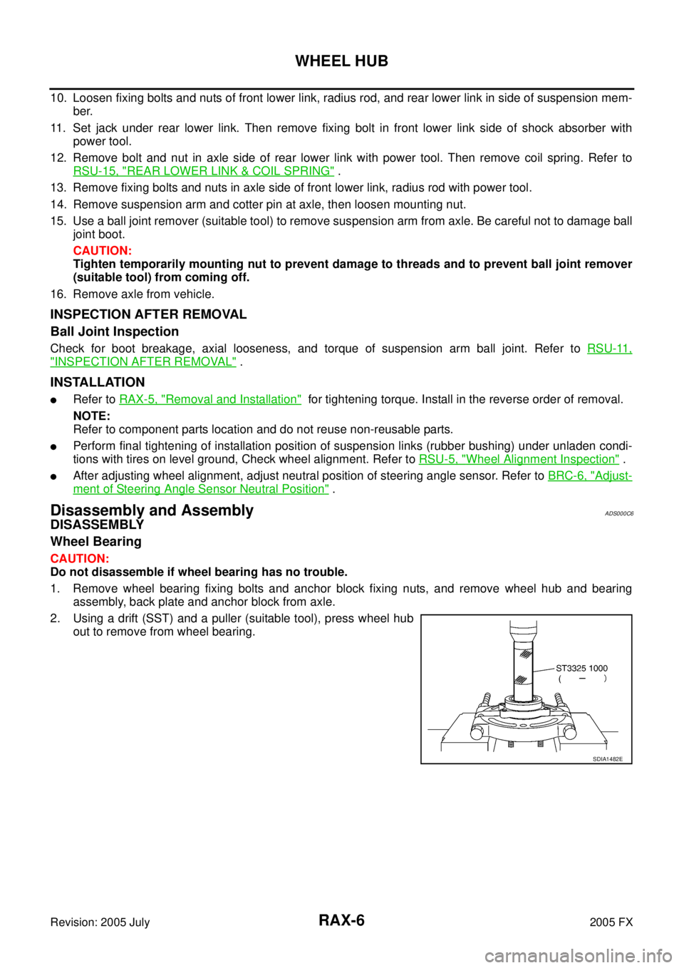
2. Using a drift (SST) and a puller (suitable tool), press wheel hub out to remove from wheel bearing.
SDIA1482E
Page 4376 of 4731
NOISE, VIBRATION AND HARSHNESS (NVH) TROUBLESHOOTING RFD-7
C E F
G H
I
J
K L
M A
B
RFD
Revision: 2005 July 2005 FX
NOISE, VIBRATION AND HARSHNESS (NVH) TROUBLESHOOTINGPFP:00003
NVH Troubleshooting ChartADS001AI
Use the chart below to help you find the cause of the symptom. If necessary, repair or replace these parts.
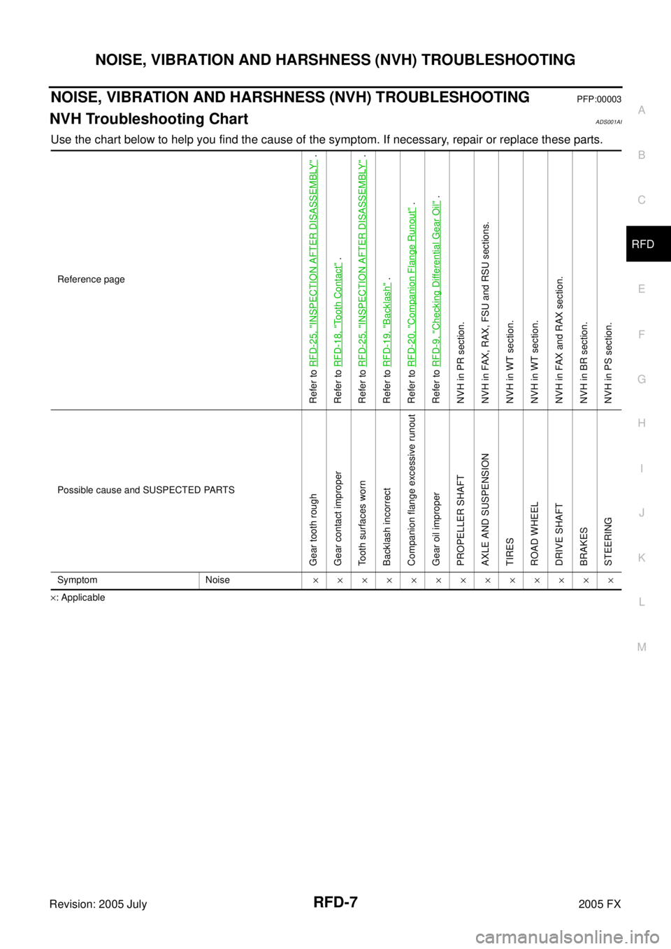
×: Applicable Reference page
Refer to
RFD-25, "
INSPECTION AFTER DISASSEMBLY
" .
Refer to RFD-18, "
Tooth Contact
" .
Refer to RFD-25, "
INSPECTION AFTER DISASSEMBLY
" .
Refer to RFD-19, "
Backlash
" .
Refer to RFD-20, "
Companion Flange Runout
" .
Refer to RFD-9, "
Checking Differential Gear Oil
" .
NVH in PR section.
NVH in FAX, RAX, FSU and RSU sections.
NVH in WT section.
NVH in WT section.
NVH in FAX and RAX section.
NVH in BR section.
NVH in PS section.
Possible cause and SUSPECTED PARTS
Gear tooth rough
Gear contact improper
Tooth surfaces worn
Backlash incorrect
Companion flange excessive runout
Gear oil improper
PROPELLER SHAFT
AXLE AND SUSPENSION
TIRES
ROAD WHEEL
DRIVE SHAFT
BRAKES
STEERING
Symptom Noise ×××××××××××××
Page 4409 of 4731
RSU-2
PRECAUTIONS
Revision: 2005 July 2005 FX
PRECAUTIONSPFP:00001
CautionsAES000MF
�When installing rubber bushings, final tightening must be carried out under unladen conditions with tires
on level ground. Oil will shorten the life of rubber bushings. Be sure to wipe off any spilled oil.
�Unladen conditions means that fuel, engine coolant and lubricant are full. Spare tire, jack, hand tools and
mats are in designated positions.
�After servicing suspension parts, be sure to check wheel alignment.
�Caulking nuts are not reusable. Always use new ones when installing. Since new caulking nuts are pre-
oiled, tighten as they are.
Page 4411 of 4731
RSU-4
NOISE, VIBRATION AND HARSHNESS (NVH) TROUBLESHOOTING
Revision: 2005 July 2005 FX
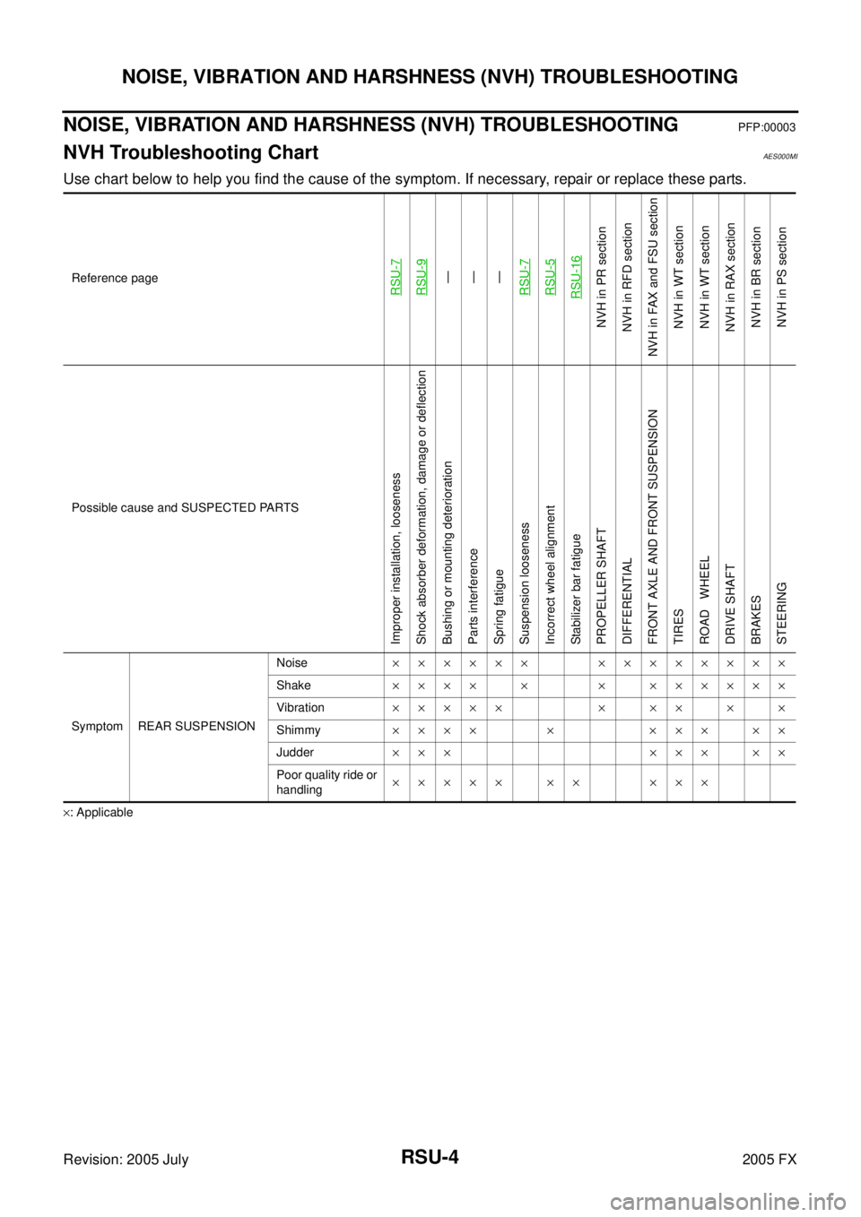
NOISE, VIBRATION AND HARSHNESS (NVH) TROUBLESHOOTINGPFP:00003
NVH Troubleshooting ChartAES000MI
Use chart below to help you find the cause of the symptom. If necessary, repair or replace these parts.
×: Applicable Reference page
RSU-7RSU-9—
—
—
RSU-7RSU-5RSU-16
NVH in PR section
NVH in RFD section
NVH in FAX and FSU section NVH in WT section
NVH in WT section
NVH in RAX section NVH in BR sectionNVH in PS section
Possible cause and SUSPECTED PARTS
Improper installation, looseness
Shock absorber deformation, damage or deflection
Bushing or mounting deterioration
Parts interference
Spring fatigue
Suspension looseness
Incorrect wheel alignment
Stabilizer bar fatigue
PROPELLER SHAFT
DIFFERENTIAL
FRONT AXLE AND FRONT SUSPENSION
TIRES
ROAD WHEEL
DRIVE SHAFT
BRAKES
STEERING
Symptom REAR SUSPENSION Noise
×××××× ××××××××
Shake ×××× × × ××××××
Vibration ××××× × ×× × ×
Shimmy ×××× × ××× ××
Judder ××× ××× ××
Poor quality ride or
handling ××××× ×× ×××
Page 4412 of 4731
REAR SUSPENSION ASSEMBLY RSU-5
C
D
F
G H
I
J
K L
M A
B
RSU
Revision: 2005 July 2005 FX
REAR SUSPENSION ASSEMBLYPFP:55020
On-Vehicle Inspection and ServiceAES000MJ
Make sure the mounting conditions (looseness, back lash) of each component and component status (wear,
damage) are normal.
INSPECTION OF SUSPENSION ARM BALL JOINT END PLAY
Measure axial end play by installing and moving up/down between suspension arm and axle with an iron pry
bar or something similar.
CAUTION:
Be careful not to damage ball joint boot.
SHOCK ABSORBER INSPECTION
Check shock absorber for oil leakage, damage and replace if necessary.
Wheel Alignment InspectionAES000MK
DESCRIPTION
Measure wheel alignment under unladen conditions. “Unladen conditions” mean that fuel, engine coolant, and
lubricant are full. Spare tire, jack, hand tools and mats are in designated positions.
PRELIMINARY CHECK
1. Check tires for improper air pressure and wear.
2. Check road wheels for runout.
3. Check wheel bearing axial end play.
4. Check suspension arm ball joint axial end play.
5. Check shock absorber operation.
6. Check each mounting part of axle and suspension for looseness and deformation.
7. Check each link, arm and member for cracks, deformation, and other damage.
8. Check vehicle posture.
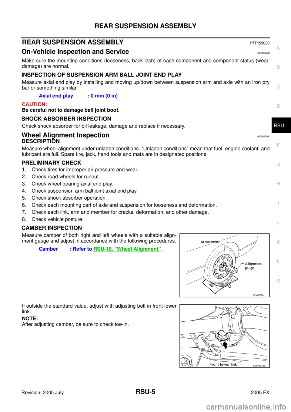
CAMBER INSPECTION
Measure camber of both right and left wheels with a suitable align-
ment gauge and adjust in accordance with the following procedures.
If outside the standard value, adjust with adjusting bolt in front lower
link.
NOTE:
After adjusting camber, be sure to check toe-in. Axial end play : 0 mm (0 in)
Camber : Refer to RSU-18, "
Wheel Alignment" .
SRA096A
SEIA0318E