Page 991 of 4731
BL-176
BACK DOOR AUTO CLOSURE SYSTEM
Revision: 2005 July 2005 FX
Back Door Closure Control Unit Power Supply and Ground Circuit CheckAIS004OK
1. CHECK POWER SUPPLY CIRCUIT
1. Turn ignition switch OFF.
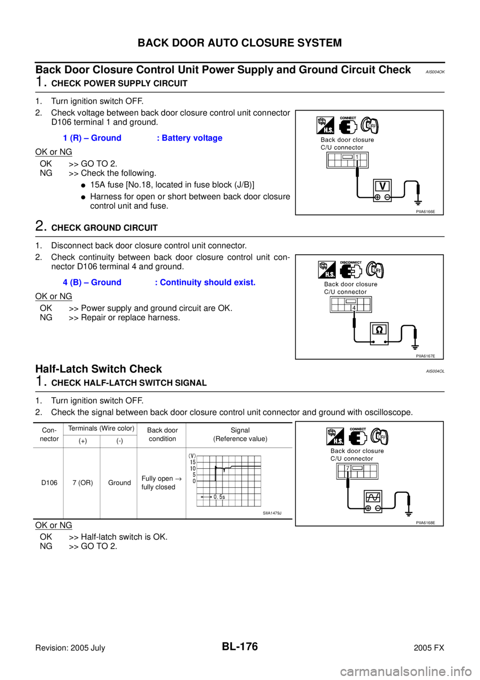
2. Check voltage between back door closure control unit connector D106 terminal 1 and ground.
OK or NG
OK >> GO TO 2.
NG >> Check the following.
�15A fuse [No.18, located in fuse block (J/B)]
�Harness for open or short between back door closure
control unit and fuse.
2. CHECK GROUND CIRCUIT
1. Disconnect back door closure control unit connector.
2. Check continuity between back door closure control unit con- nector D106 terminal 4 and ground.
OK or NG
OK >> Power supply and ground circuit are OK.
NG >> Repair or replace harness.
Half-Latch Switch CheckAIS004OL
1. CHECK HALF-LATCH SWITCH SIGNAL
1. Turn ignition switch OFF.
2. Check the signal between back door closure control unit connector and ground with oscilloscope.
OK or NG
OK >> Half-latch switch is OK.
NG >> GO TO 2. 1 (R) – Ground : Battery voltage
PIIA6166E
4 (B) – Ground : Continuity should exist.
PIIA6167E
Con-
nector Terminals (Wire color)
Back door
condition Signal
(Reference value)
(+) (-)
D106 7 (OR) Ground Fully open
→
fully closed
PIIA6168E
SIIA1479J
Page 993 of 4731
BL-178
BACK DOOR AUTO CLOSURE SYSTEM
Revision: 2005 July 2005 FX
Close Switch CheckAIS004OM
1. CHECK CLOSE SWITCH SIGNAL
1. Turn ignition switch OFF.
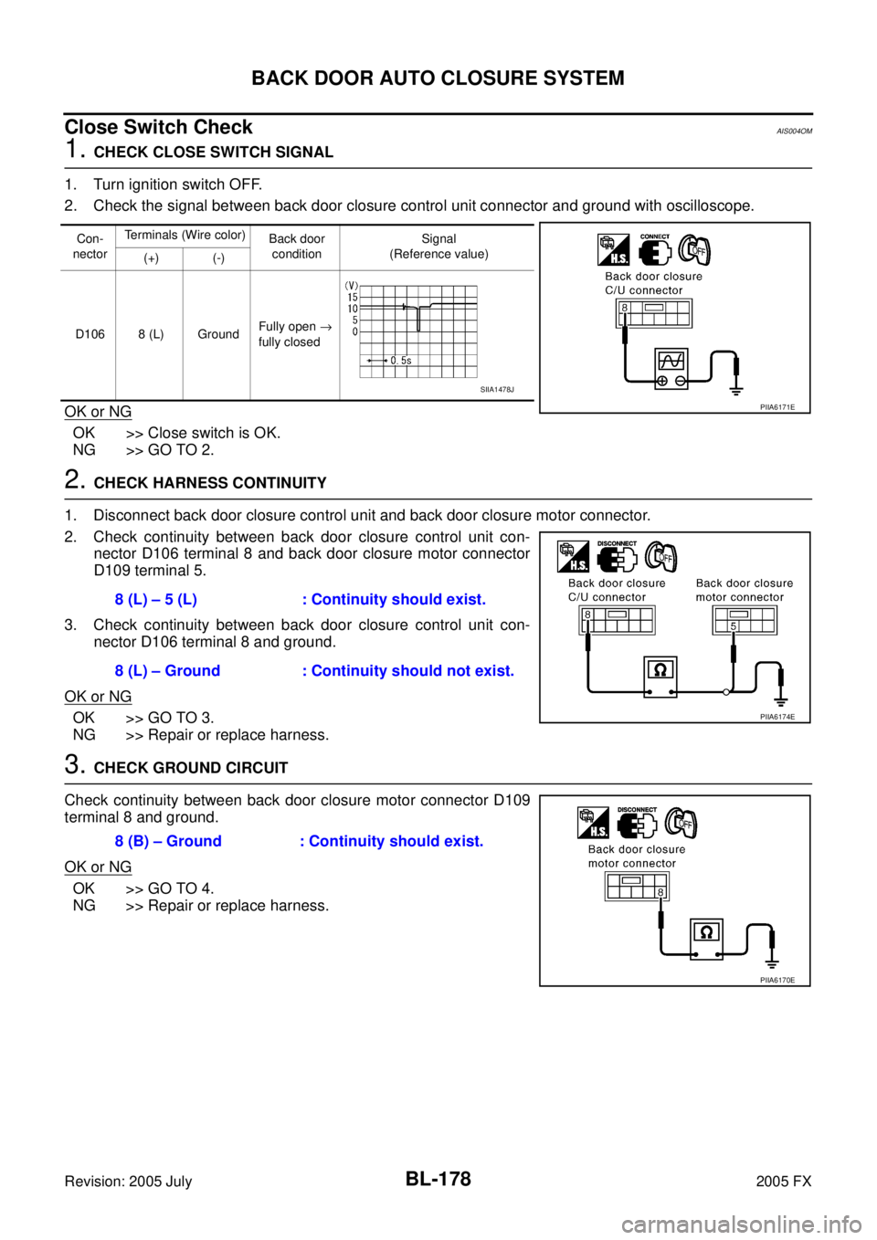
2. Check the signal between back door closure control unit connector and ground with oscilloscope.
OK or NG
OK >> Close switch is OK.
NG >> GO TO 2.
2. CHECK HARNESS CONTINUITY
1. Disconnect back door closure control unit and back door closure motor connector.
2. Check continuity between back door closure control unit con- nector D106 terminal 8 and back door closure motor connector
D109 terminal 5.
3. Check continuity between back door closure control unit con- nector D106 terminal 8 and ground.
OK or NG
OK >> GO TO 3.
NG >> Repair or replace harness.
3. CHECK GROUND CIRCUIT
Check continuity between back door closure motor connector D109
terminal 8 and ground.
OK or NG
OK >> GO TO 4.
NG >> Repair or replace harness.
Con-
nector Terminals (Wire color)
Back door
condition Signal
(Reference value)
(+) (-)
D106 8 (L) Ground Fully open
→
fully closed
PIIA6171E
SIIA1478J
8 (L) – 5 (L) : Continuity should exist.
8 (L) – Ground : Continuity should not exist.
PIIA6174E
8 (B) – Ground : Continuity should exist.
PIIA6170E
Page 994 of 4731

BACK DOOR AUTO CLOSURE SYSTEM BL-179
C
D E
F
G H
J
K L
M A
B
BL
Revision: 2005 July 2005 FX
4. CHECK BACK DOOR CLOSURE CONTROL UNIT OUTPUT SIGNAL
1. Connect back door closure control unit connector.
2. Check voltage between back door closure control unit connector D106 terminal 8 and ground.
OK or NG
OK >> Replace back door lock assembly.
NG >> Replace back door closure control unit.
Open Switch CheckAIS004ON
1. CHECK OPEN SWITCH SIGNAL
1. Turn ignition switch OFF.
2. Check the signal between back door closure control unit connector and ground with oscilloscope.
OK or NG
OK >> Open switch is OK.
NG >> GO TO 2.
2. CHECK HARNESS CONTINUITY
1. Disconnect back door closure control unit and back door closure motor connector.
2. Check continuity between back door closure control unit con- nector D106 terminal 9 and back door closure motor connector
D109 terminal 4.
3. Check continuity between back door closure control unit con- nector D106 terminal 9 and ground.
OK or NG
OK >> GO TO 3.
NG >> Repair or replace harness. Back door is closed
8 (L) – Ground : Battery voltage
PIIA6173E
Con-
nector Terminals (Wire color)
Back door
condition Signal
(Reference value)
(+) (-)
D106 9 (P) Ground Fully open
→
fully closed
PIIA6175E
SIIA1481J
9 (P) – 4 (P) : Continuity should exist.
9 (P) – Ground : Continuity should not exist.
PIIA6176E
Page 995 of 4731
BL-180
BACK DOOR AUTO CLOSURE SYSTEM
Revision: 2005 July 2005 FX
3. CHECK GROUND CIRCUIT
Check continuity between back door closure motor connector D109
terminal 8 and ground.
OK or NG
OK >> GO TO 4.
NG >> Repair or replace harness.
4. CHECK BACK DOOR CLOSURE CONTROL UNIT OUTPUT SIGNAL
1. Connect back door closure control unit connector.
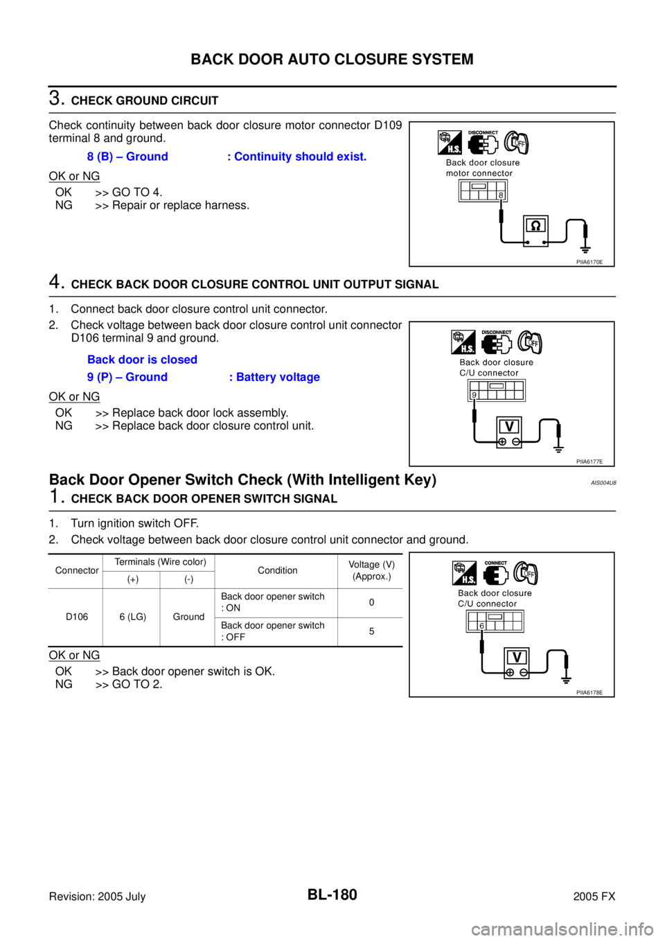
2. Check voltage between back door closure control unit connector D106 terminal 9 and ground.
OK or NG
OK >> Replace back door lock assembly.
NG >> Replace back door closure control unit.
Back Door Opener Switch Check (With Intelligent Key)AIS004U8
1. CHECK BACK DOOR OPENER SWITCH SIGNAL
1. Turn ignition switch OFF.
2. Check voltage between back door closure control unit connector and ground.
OK or NG
OK >> Back door opener switch is OK.
NG >> GO TO 2. 8 (B) – Ground : Continuity should exist.
PIIA6170E
Back door is closed
9 (P) – Ground : Battery voltage
PIIA6177E
Connector Terminals (Wire color)
Condition Voltage (V)
(Approx.)
(+) (-)
D106 6 (LG) Ground Back door opener switch
: ON 0
Back door opener switch
: OFF 5
PIIA6178E
Page 997 of 4731
BL-182
BACK DOOR AUTO CLOSURE SYSTEM
Revision: 2005 July 2005 FX
6. CHECK BACK DOOR CLOSURE CONTROL UNIT OUTPUT SIGNAL
1. Connect back door closure control unit connector.
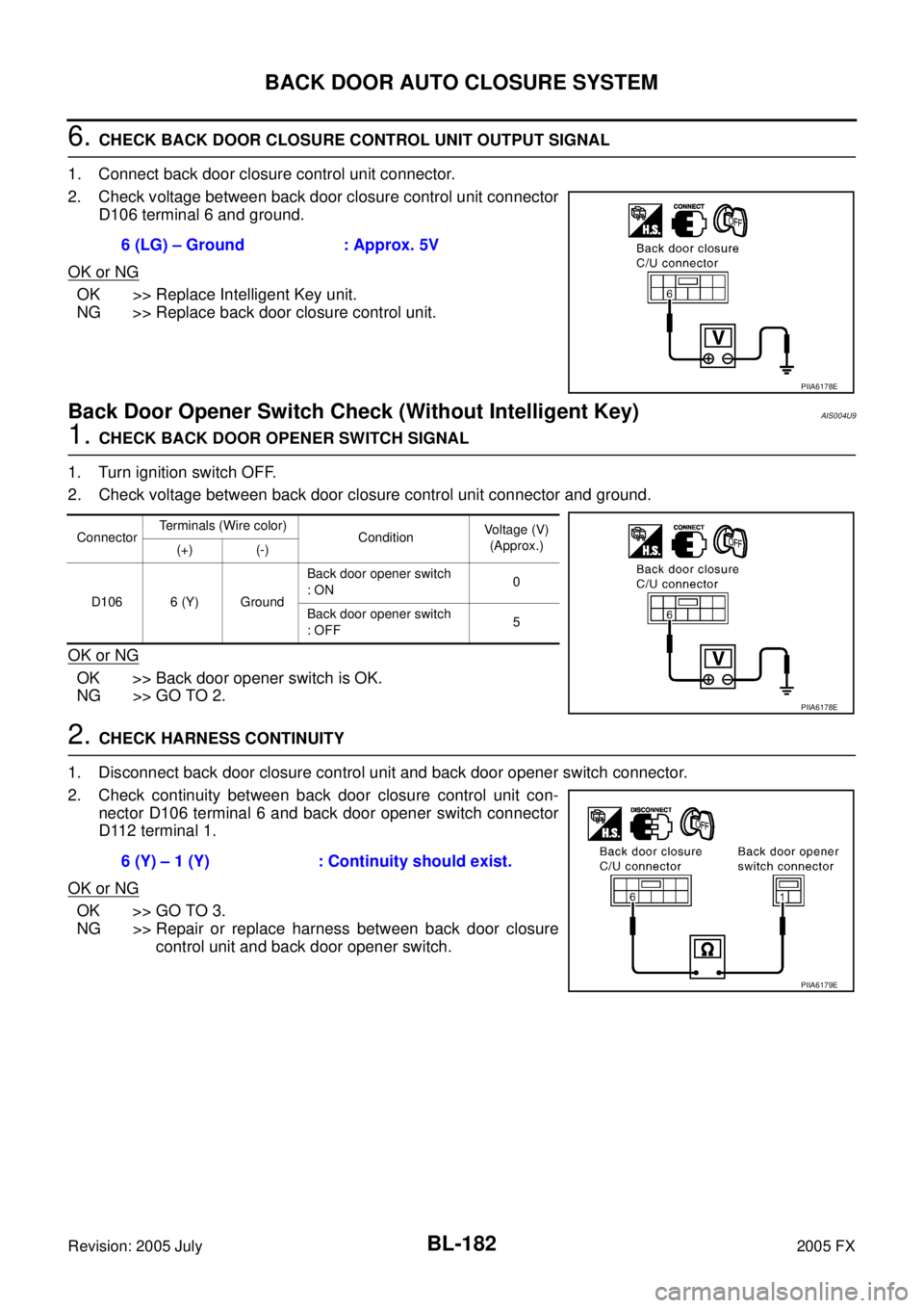
2. Check voltage between back door closure control unit connector D106 terminal 6 and ground.
OK or NG
OK >> Replace Intelligent Key unit.
NG >> Replace back door closure control unit.
Back Door Opener Switch Check (Without Intelligent Key)AIS004U9
1. CHECK BACK DOOR OPENER SWITCH SIGNAL
1. Turn ignition switch OFF.
2. Check voltage between back door closure control unit connector and ground.
OK or NG
OK >> Back door opener switch is OK.
NG >> GO TO 2.
2. CHECK HARNESS CONTINUITY
1. Disconnect back door closure control unit and back door opener switch connector.
2. Check continuity between back door closure control unit con- nector D106 terminal 6 and back door opener switch connector
D112 terminal 1.
OK or NG
OK >> GO TO 3.
NG >> Repair or replace harness between back door closure control unit and back door opener switch.
6 (LG) – Ground : Approx. 5V
PIIA6178E
Connector
Terminals (Wire color)
Condition Voltage (V)
(Approx.)
(+) (-)
D106 6 (Y) Ground Back door opener switch
: ON 0
Back door opener switch
: OFF 5
PIIA6178E
6 (Y) – 1 (Y) : Continuity should exist.
PIIA6179E
Page 999 of 4731

BL-184
BACK DOOR AUTO CLOSURE SYSTEM
Revision: 2005 July 2005 FX
Unlock Sensor Check (Without Intelligent Key)AIS004UA
1. CHECK UNLOCK SENSOR SIGNAL
1. Turn ignition switch OFF.
2. Check voltage between back door closure control unit connector and ground.
OK or NG
OK >> Unlock sensor is OK.
NG >> GO TO 2.
2. CHECK HARNESS CONTINUITY
1. Disconnect back door closure control unit and front door lock assembly (passenger side) connector.
2. Check continuity between back door closure control unit con- nector D106 terminal 5 and front door lock assembly (passenger
side) connector D40 terminal 5.
OK or NG
OK >> GO TO 3.
NG >> Repair or replace harness between back door closure
control unit and front door lock assembly (passenger
side).
3. CHECK GROUND CIRCUIT
Check continuity between front door lock assembly (passenger side)
connector D40 terminal 4 and ground.
OK or NG
OK >> GO TO 4.
NG >> Repair or replace harness.
Connector Terminals (Wire color)
Condition Voltage (V)
(Approx.)
(+) (-)
D106 5 (W) Ground Passenger side door lock is
locked 5
Passenger side door lock is
unlocked 0
PIIA6182E
5 (W) – 5 (W) : Continuity should exist.
PIIA6183E
4 (B) – Ground : Continuity should exist.
PIIA6184E
Page 1000 of 4731

BACK DOOR AUTO CLOSURE SYSTEM BL-185
C
D E
F
G H
J
K L
M A
B
BL
Revision: 2005 July 2005 FX
4. CHECK BACK DOOR CLOSURE CONTROL UNIT OUTPUT SIGNAL
1. Connect back door closure control unit connector.
2. Check voltage between back door closure control unit connector D106 terminal 5 and ground.
OK or NG
OK >> Replace front door lock assembly (passenger side).
NG >> Replace back door closure control unit.
Closure Motor CheckAIS004UB
1. CHECK BACK DOOR CLOSURE MOTOR
1. Turn ignition switch OFF.
2. Check the signal between back door closure control unit connector and ground with oscilloscope.
OK or NG
OK >> GO TO 2.
NG >> Replace back door closure control unit.
2. CHECK HARNESS CONTINUITY
1. Disconnect back door closure control unit and back door closure motor connector.
2. Check continuity between back door closure control unit con- nector D106 terminals 2, 3 and back door closure motor connec-
tor D109 terminals 1, 2.
3. Check continuity between back door closure control unit con- nector D106 terminals 2, 3 and ground.
OK or NG
OK >> Replace back door closure motor.
NG >> Repair or replace harness.
Removal and Installation of Back Door Closer Control UnitAIS004UC
1. Remove the back door finisher. EI-45, "Removal and Installation" .
2. Disconnect the back door closer control unit harness, remove the screw and back door closer control unit. 5 (W) – Ground : Approx. 5V
PIIA6182E
Con-
nector Terminals (Wire color)
Back door
condition Signal
(Reference value)
(+) (-)
D106 2 (PU)
Ground Fully closed
→ fully open
3 (G) Fully open
→
fully closed
PIIA6185E
SIIA1480J
2 (PU) – 1 (PU) : Continuity should exist.
3 (G) – 2 (G) : Continuity should exist.
2 (PU) – Ground : Continuity should not exist.
3 (G) – Ground : Continuity should not exist.
PIIA6186E
Page 1003 of 4731
BL-188
VEHICLE SECURITY (THEFT WARNING) SYSTEM
Revision: 2005 July 2005 FX
System DescriptionAIS004OT
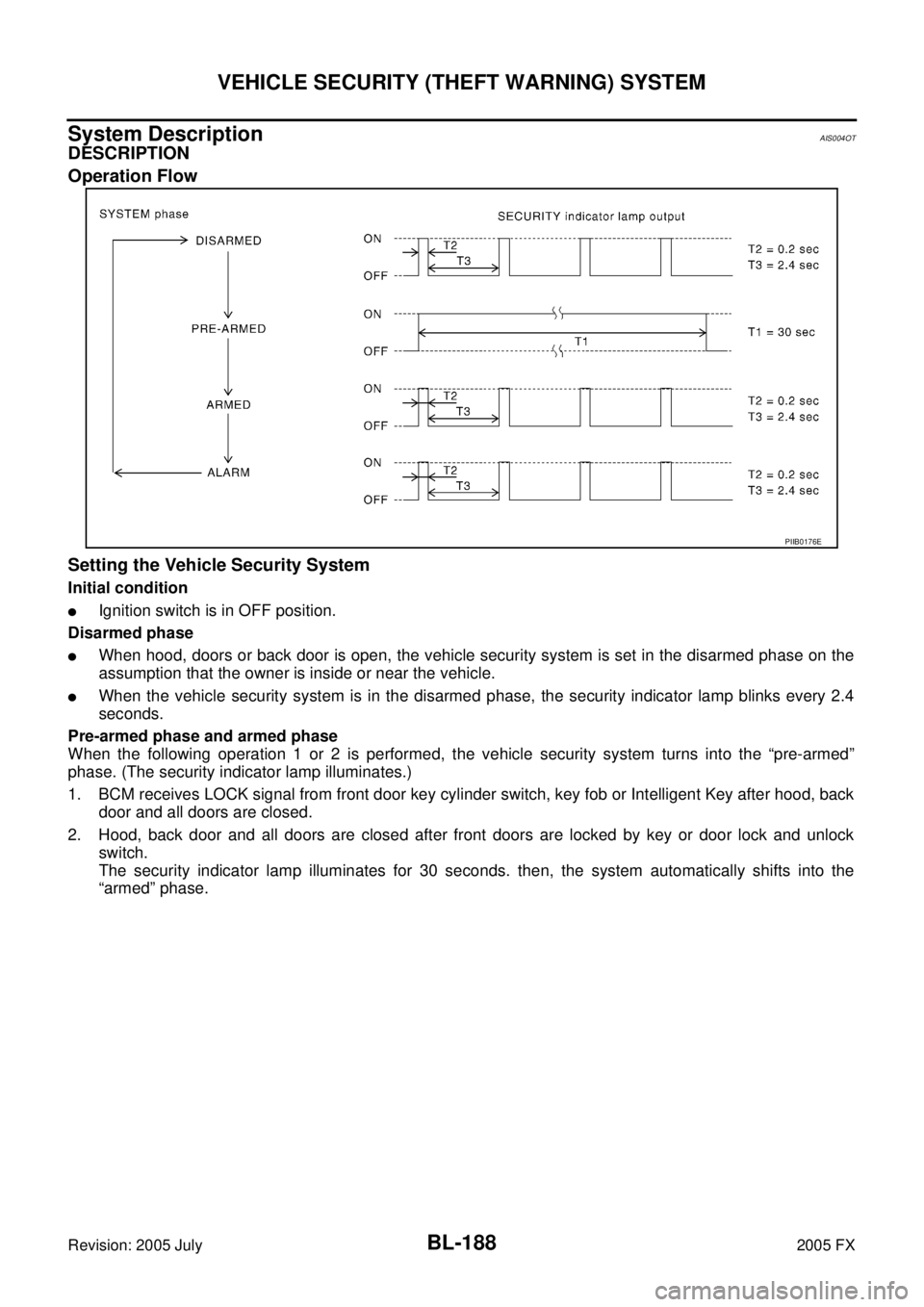
DESCRIPTION
Operation Flow
Setting the Vehicle Security System
Initial condition
�Ignition switch is in OFF position.
Disarmed phase
�When hood, doors or back door is open, the vehicle security system is set in the disarmed phase on the
assumption that the owner is inside or near the vehicle.
�When the vehicle security system is in the disarmed phase, the security indicator lamp blinks every 2.4
seconds.
Pre-armed phase and armed phase
When the following operation 1 or 2 is performed, the vehicle security system turns into the “pre-armed”
phase. (The security indicator lamp illuminates.)
1. BCM receives LOCK signal from front door key cylinder switch, key fob or Intelligent Key after hood, back door and all doors are closed.
2. Hood, back door and all doors are closed after front doors are locked by key or door lock and unlock switch.
The security indicator lamp illuminates for 30 seconds. then, the system automatically shifts into the
“armed” phase.
PIIB0176E