Page 946 of 4731
AIS004ND
1. CHECK KEY SWITCH POWER SUPPLY CIRCUIT
1. Turn ignition knob O")
INTELLIGENT KEY SYSTEM BL-131
C
D E
F
G H
J
K L
M A
B
BL
Revision: 2005 July 2005 FX
Check Key Switch (BCM Input)AIS004ND
1. CHECK KEY SWITCH POWER SUPPLY CIRCUIT
1. Turn ignition knob OFF position.
2. Disconnect key switch and ignition knob switch connector.
3. Check voltage between key switch and ignition knob switch con- nector M22 terminal 3 (L/R) and ground.
OK or NG
OK >> GO TO 2.
NG >> Check harness between key switch and ignition knob switch and fuse.
2. CHECK KEY SWITCH
Check continuity between key switch and ignition knob switch as fol-
lows.
OK or NG
OK >> GO TO 3.
NG >> Replace key switch and ignition knob switch.
3. CHECK KEY SWITCH SIGNAL CIRCUIT
1. Disconnect key switch and ignition knob switch connector and BCM connector.
2. Check continuity between key switch and ignition knob switch connector M22 terminal 4 (B/W) and BCM connector M3 termi-
nal 37 (B/W).
3. Check continuity between key switch and ignition knob switch connector M22 terminal 4 (B/W) and ground.
OK or NG
OK >> Key switch (BCM input) circuit is OK.
NG >> Repair or replace harness between key switch and ignition knob switch and BCM. 3 (L/R) – Ground : Battery voltage.
PIIA5093E
Terminals Condition Continuity
34 Key is inserted in ignition key cylinder. Yes
Key is removed from ignition key cylinder. No
PIIA6140E
4 (B/W) – 37 (B/W) : Continuity should exist.
4 (B/W) – Ground : Continuity should not exist.
PIIA5095E
Page 948 of 4731

INTELLIGENT KEY SYSTEM BL-133
C
D E
F
G H
J
K L
M A
B
BL
Revision: 2005 July 2005 FX
4. CHECK IGNITION KNOB SWITCH CIRCUIT
1. Disconnect Intelligent Key unit connector.
2. Check continuity between Intelligent Key unit connector M34 terminal 27 (L/W) and key switch and igni- tion knob switch connector M22 terminal 2 (L/W).
3. Check continuity between key switch and ignition knob switch connector terminal 2 (L/W) and ground.
OK or NG
OK >> Replace Intelligent Key unit.
NG >> Repair or replace harness between Intelligent Key unit
and key switch and ignition knob switch.
Check Door SwitchAIS004NF
CHECK DOOR SWITCH (EXCEPT BACK DOOR SWITCH)
1. CHECK DOOR SWITCH INPUT SIGNAL
1. Turn ignition knob LOCK position.
2. Check voltage between BCM connector and ground.
OK or NG
OK >> Door switch circuit is OK.
NG >> GO TO 2. 27 (L/W) - 2 (L/W) : Continuity should exist.
2 (L/W) - Ground : Continuity should not exist.
PIIA6743E
Item Connector Terminals
(Wire color) Door
condition Voltage (V)
(Approx.)
(+) (-)
Driver side B14 62 (W)
Ground CLOSE
↓
OPEN Battery voltage
↓
0
Rear LH 63 (P)
Passenger side M3 12 (P/B)
Rear RH 13 (P/L)
PIIA7003E
Page 951 of 4731

BL-136
INTELLIGENT KEY SYSTEM
Revision: 2005 July 2005 FX
5. CHECK BCM OUTPUT SIGNAL
1. Connect BCM connector.
2. Check voltage between BCM connector and ground.
OK or NG
OK >> Check condition of harness and connector.
NG >> Replace BCM.
Check Unlock SensorAIS004NG
1. CHECK UNLOCK SENSOR POWER SUPPLY
Check voltage between Intelligent Key unit connector and ground.
OK or NG
OK >> Unlock sensor is OK.
NG >> GO TO 2.
2. CHECK UNLOCK SENSOR CIRCUIT
1. Turn ignition knob LOCK position.
2. Disconnect Intelligent Key unit and front door lock assembly (driver side) connector.
3. Check continuity between Intelligent Key unit connector M34 terminal 28 (W/B) and front door lock assembly (driver side) connector D10 terminal 4 (W).
OK or NG
OK >> GO TO 3.
NG >> Repair or replace harness between Intelligent Key unit and front door lock assembly (driver side).
58 (L) – Ground : Approx. 9V
PIIA6229E
Connector
Terminals (Wire color)
Condition Voltage (V)
(Approx.)
(+) (-)
M34 28 (W/B) Ground Driver side door lock is
locked 5
Driver side door lock is
unlocked 0
PIIA6802E
28 (W/B) – 4 (W) : Continuity should exist.
PIIA6803E
Page 953 of 4731

BL-138
INTELLIGENT KEY SYSTEM
Revision: 2005 July 2005 FX
2. CHECK DOOR REQUEST SWITCH SIGNAL
1. Turn ignition knob LOCK position.
2. Disconnect door request switch connector.
3. Check voltage between door request switch connector D12 (driver door), D42 (passenger door), D113 (back door) terminal 1 and ground.
OK or NG
OK >> GO TO 3.
NG >> GO TO 5.
3. CHECK DOOR REQUEST SWITCH OPERATION
Check continuity between door request switch D12 (driver door), D42 (passenger door), D113 (back door) ter-
minals 1 and 2.
OK or NG
OK >> GO TO 4.
NG >> Replace door request switch.
4. CHECK DOOR REQUEST SWITCH GROUND CIRCUIT
Check continuity between door request switch connector D12 (driver side), D42 (passenger side), D113 (back
door) terminal 2 (B) and ground.
OK or NG
OK >> Check harness connection.
NG >> Repair or replace door request switch ground circuit. Driver 1 (SB) - Ground : Approx. 5V
Passenger 1 (GY) - Ground : Approx. 5V
Back door 1 (GY) - Ground : Approx. 5V
PIIA6744E
Terminal Condition Continuity
12 Press door request switch Yes
Return door request switch No
PIIA9930E
2 (B) - Ground : Continuity should exist.
PIIA6746E
Page 962 of 4731
INTELLIGENT KEY SYSTEM BL-147
C
D E
F
G H
J
K L
M A
B
BL
Revision: 2005 July 2005 FX
3. CHECK STOP LAMP SWITCH GROUND CIRCUIT
1. Check continuity between stop lamp switch connector E210 ter- minal 2 (P) and Intelligent Key unit connector M34 terminal 26
(P/L).
2. Check continuity between stop lamp switch connector E210 ter- minal 2 (P) and ground.
OK or NG
OK >> Stop lamp switch is OK.
NG >> Repair or replace harness.
Check Detention SwitchAIS004NN
1. CHECK DETENTION SWITCH INPUT SIGNAL
1. Turn ignition knob LOCK position.
2. Check voltage between Intelligent Key unit connector and ground.
OK or NG
OK >> Door switch circuit is OK.
NG >> GO TO 2. 2 (P) - 26 (P/L) : Continuity should exist.
2 (P) - Ground : Continuity should not exist.
PIIA6801E
Connector Terminal
(Wire color) Condition Voltage (V)
(Approx.)
(+) (-)
M34 39 (R/Y) Ground When selector lever is locked
at the “P” position 0
When selector lever is not
locked at the “P” position Battery voltage
PIIA6805E
Page 965 of 4731

BL-150
INTELLIGENT KEY SYSTEM
Revision: 2005 July 2005 FX
Check Hazard FunctionAIS004NP
1. CHECK HAZARD WARNING LAMP
Does hazard warning lamp flash with hazard switch?
YES or NO
YES >> Hazard warning lamp circuit is OK.
NO >> Check hazard circuit. Refer to LT- 9 1 , "
TURN SIGNAL AND HAZARD WARNING LAMPS" .
Check Horn FunctionAIS004NQ
First perform the “SELF-DIAG RESULTS” in “BCM” with CONSULT-II, then perform the trouble diagnosis of
malfunction system indicated “SELF-DIAG RESULTS” of “BCM”. Refer to BCS-15, "
CAN Communication
Inspection Using CONSULT-II (Self-Diagnosis)" .
1. CHECK HORN FUNCTION
Does horn sound with horn switch?
YES or NO
YES >> Horn circuit is OK.
NO >> Check horn circuit. Refer to WW-59, "
HORN" .
Check Headlamp FunctionAIS004NR
First perform the “SELF-DIAG RESULTS” in “BCM” with CONSULT-II, then perform the trouble diagnosis of
malfunction system indicated “SELF-DIAG RESULTS” of “BCM”. Refer to BCS-15, "
CAN Communication
Inspection Using CONSULT-II (Self-Diagnosis)" .
1. CHECK HEADLAMP OPERATION
Does headlamp come on when turning lighting switch “ON”?
YES or NO
YES >> Headlamp operation circuit is OK.
NO >> Check headlamp system. Refer to LT- 7 , "
HEADLAMP - XENON TYPE -" .
Check IPDM E/R OperationAIS004NS
1. CHECK IPDM E/R INPUT VOLTAGE
Check voltage between IPDM E/R connector E9 terminal 51 (SB) and ground.
OK or NG
OK >> Replace IPDM E/R.
NG >> GO TO 2. 51 (SB) – Ground : Battery voltage
PIIA6403E
Page 985 of 4731

BL-170
BACK DOOR AUTO CLOSURE SYSTEM
Revision: 2005 July 2005 FX
BACK DOOR AUTO CLOSURE SYSTEMPFP:90542
Component Parts and Harness Connector LocationAIS004OD
System DescriptionAIS004OE
When back door lock latch engaged with striker, striker is lowered by means of a motor the back door fully
closed.
CLOSE OPERATION
�Half-latch is turned off when back door enters the state of a half door and back door closure control unit
recognizes it.
�Back door closure control unit by which the signal is recognized operates closure motor in the close direc-
tion, and open switch is turned on.
�Close switch is turned on when back door becomes a full latch position by operating closure motor and
back door closure control unit operates closure motor in an open direction.
�The operation of closure motor is stopped, and back door enters all close states when back door moves in
an open direction, and open switch is turned off.
NON-OPERATION CONDITION
�When you close back door while pushing back door opener switch.
�When closing at once (within about 0.5 seconds) after back door is opened.
�When you do not close back door after back door opener switch is pushed.
PIIA6406E
Page 986 of 4731
BACK DOOR AUTO CLOSURE SYSTEM BL-171
C
D E
F
G H
J
K L
M A
B
BL
Revision: 2005 July 2005 FX
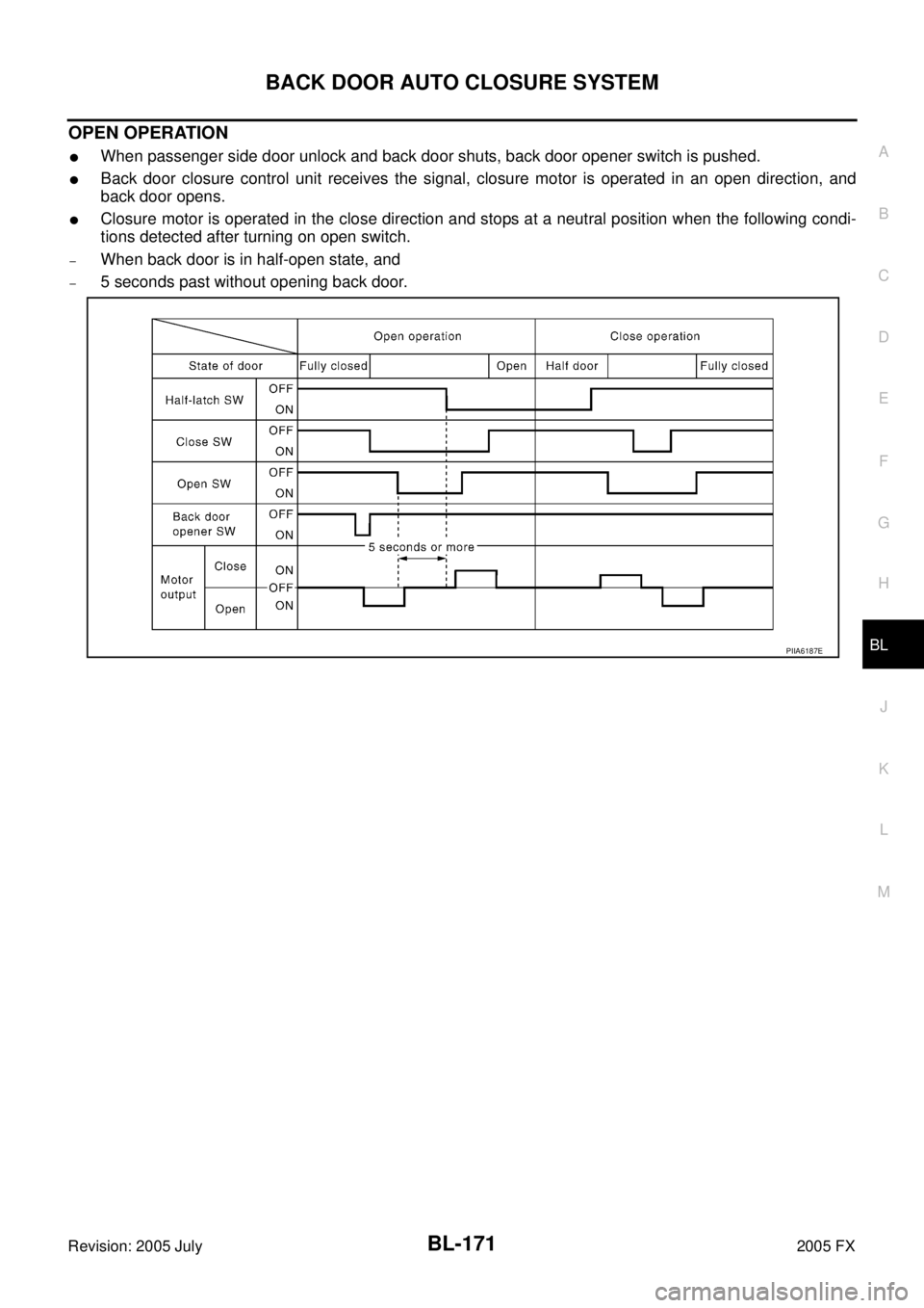
OPEN OPERATION
�When passenger side door unlock and back door shuts, back door opener switch is pushed.
�Back door closure control unit receives the signal, closure motor is operated in an open direction, and
back door opens.
�Closure motor is operated in the close direction and stops at a neutral position when the following condi-
tions detected after turning on open switch.
–When back door is in half-open state, and
–5 seconds past without opening back door.
PIIA6187E