Page 4713 of 4731

WT-20
TROUBLE DIAGNOSES
Revision: 2005 July 2005 FX
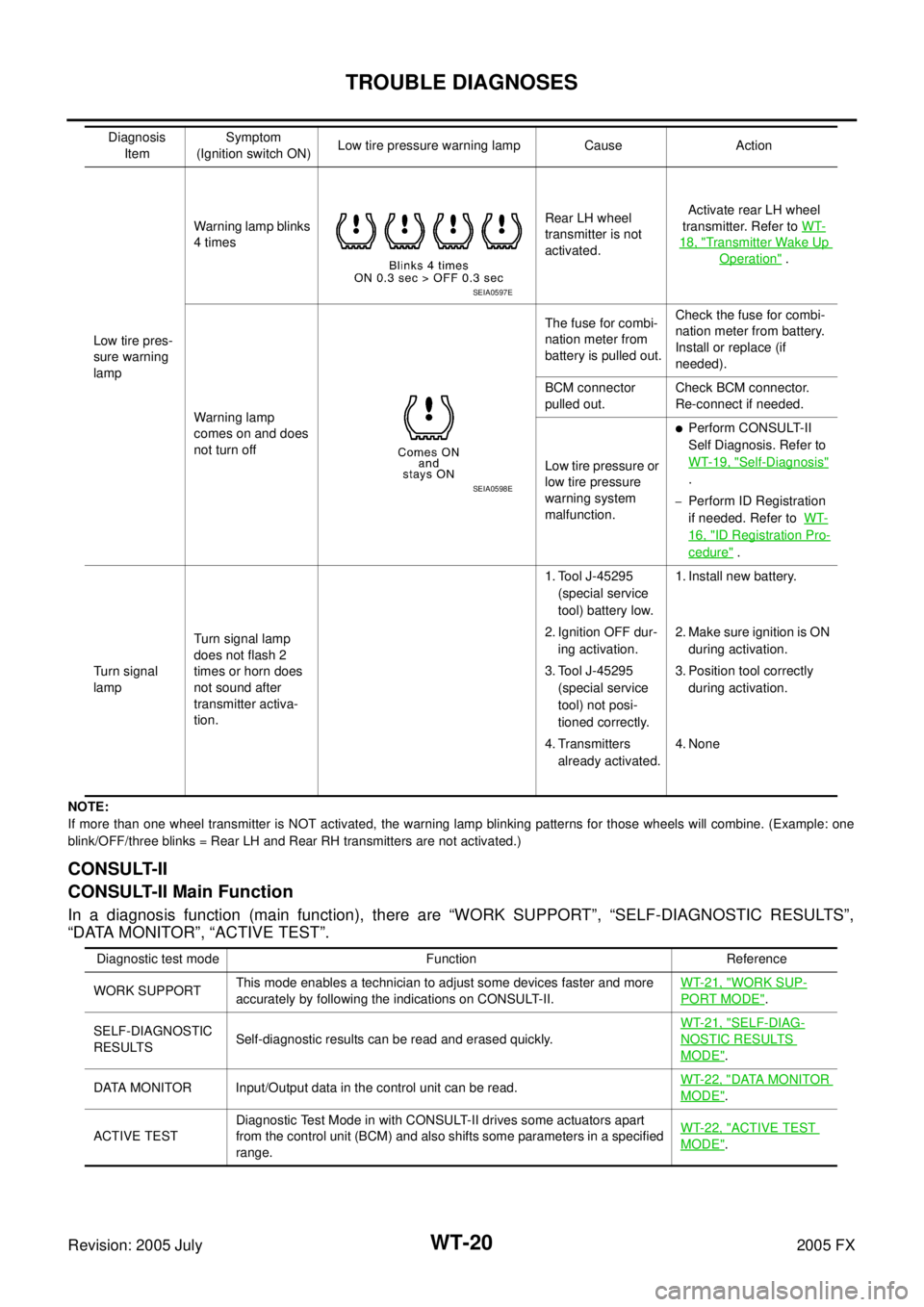
NOTE:
If more than one wheel transmitter is NOT activated, the warning lamp blinking patterns for those wheels will combine. (Example : one
blink/OFF/three blinks = Rear LH and Rear RH transmitters are not activated.)
CONSULT-II
CONSULT-II Main Function
In a diagnosis function (main function), there are “WORK SUPPORT”, “SELF-DIAGNOSTIC RESULTS”,
“DATA MONITOR”, “ACTIVE TEST”.
Low tire pres-
sure warning
lamp Warning lamp blinks
4 times Rear LH wheel
transmitter is not
activated. Activate rear LH wheel
transmitter. Refer to WT-
18, "Transmitter Wake Up
Operation" .
Warning lamp
comes on and does
not turn off The fuse for combi-
nation meter from
battery is pulled out. Check the fuse for combi-
nation meter from battery.
Install or replace (if
needed).
BCM connector
pulled out. Check BCM connector.
Re-connect if needed.
Low tire pressure or
low tire pressure
warning system
malfunction.
�Perform CONSULT-II
Self Diagnosis. Refer to
WT-19, "
Self-Diagnosis"
.
–Perform ID Registration
if needed. Refer to WT-
16, "ID Registration Pro-
cedure" .
Turn signal
lamp Turn signal lamp
does not flash 2
times or horn does
not sound after
transmitter activa-
tion. 1. Tool J-45295
(special service
tool) battery low.
2. Ignition OFF dur- ing activation.
3. Tool J-45295 (special service
tool) not posi-
tioned correctly.
4. Transmitters already activated. 1. Install new battery.
2. Make sure ignition is ON during activation.
3. Position tool correctly during activation.
4. None
Diagnosis
Item Symptom
(Ignition switch ON) Low tire pressure warning lamp Cause Action
SEIA0597E
SEIA0598E
Diagnostic test mode Function Reference
WORK SUPPORT This mode enables a technician to adjust some devices faster and more
accurately by following the indications on CONSULT-II. WT-21, "
WORK SUP-
PORT MODE".
SELF-DIAGNOSTIC
RESULTS Self-diagnostic results can be read and erased quickly. WT-21, "
SELF-DIAG-
NOSTIC RESULTS
MODE".
DATA MONITOR Input/Output data in the control unit can be read. WT-22, "
DATA MONITOR
MODE".
ACTIVE TEST Diagnostic Test Mode in with CONSULT-II drives some actuators apart
from the control unit (BCM) and also shifts some parameters in a specified
range. WT-22, "
ACTIVE TEST
MODE".
Page 4716 of 4731
TROUBLE DIAGNOSES WT-23
C
D
F
G H
I
J
K L
M A
B
WT
Revision: 2005 July 2005 FX
Flasher
Touch “LH” and “RH” on the display, and then check to make sure
that each turn signal lamp turns on.
Horn
Touch “LH” and “RH” on the display, and then check to make sure
that the horn sounds.
Warning Lamp
Touch “LH” and “RH” on the display, and then check to make sure
that the warning lamp turns on.
ID Regist Warning
Touch “LH” and “RH” on the display, and then check to make sure
that the buzzer sounds or the warning lamp turns on.
SEIA0586E
SEIA0587E
SEIA0588E
SEIA0589E
Page 4720 of 4731

TROUBLE DIAGNOSES WT-27
C
D
F
G H
I
J
K L
M A
B
WT
Revision: 2005 July 2005 FX
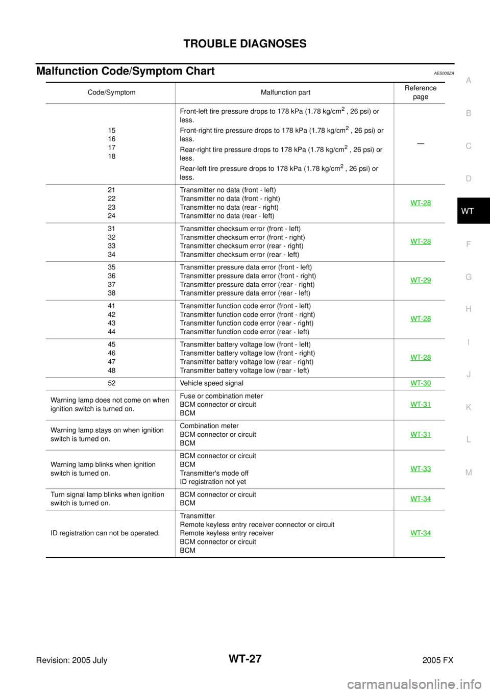
Malfunction Code/Symptom ChartAES000ZA
Code/Symptom Malfunction part Reference
page
15
16
17
18 Front-left tire pressure drops to 178 kPa (1.78 kg/cm
2 , 26 psi) or
less.
Front-right tire pressure drops to 178 kPa (1.78 kg/cm
2 , 26 psi) or
less.
Rear-right tire pressure drops to 178 kPa (1.78 kg/cm
2 , 26 psi) or
less.
Rear-left tire pressure drops to 178 kPa (1.78 kg/cm
2 , 26 psi) or
less. —
21
22
23
24 Transmitter no data (front - left)
Transmitter no data (front - right)
Transmitter no data (rear - right)
Transmitter no data (rear - left) WT-28
31
32
33
34 Transmitter checksum error (front - left)
Transmitter checksum error (front - right)
Transmitter checksum error (rear - right)
Transmitter checksum error (rear - left) WT-28
35
36
37
38 Transmitter pressure data error (front - left)
Transmitter pressure data error (front - right)
Transmitter pressure data error (rear - right)
Transmitter pressure data error (rear - left) WT-29
41
42
43
44 Transmitter function code error (front - left)
Transmitter function code error (front - right)
Transmitter function code error (rear - right)
Transmitter function code error (rear - left) WT-28
45
46
47
48 Transmitter battery voltage low (front - left)
Transmitter battery voltage low (front - right)
Transmitter battery voltage low (rear - right)
Transmitter battery voltage low (rear - left) WT-28
52 Vehicle speed signal
WT-30
Warning lamp does not come on when
ignition switch is turned on. Fuse or combination meter
BCM connector or circuit
BCM WT-31
Warning lamp stays on when ignition
switch is turned on. Combination meter
BCM connector or circuit
BCM WT-31
Warning lamp blinks when ignition
switch is turned on. BCM connector or circuit
BCM
Transmitter's mode off
ID registration not yet WT-33
Turn signal lamp blinks when ignition
switch is turned on. BCM connector or circuit
BCM WT-34
ID registration can not be operated. Transmitter
Remote keyless entry receiver connector or circuit
Remote keyless entry receiver
BCM connector or circuit
BCM WT-34
Page 4723 of 4731
WT-30
TROUBLE DIAGNOSIS FOR SELF-DIAGNOSTIC ITEMS
Revision: 2005 July 2005 FX
Inspection 4: Vehicle Speed SignalAES000ZE
MALFUNCTION CODE NO. 52
1. CHECK SELF-DIAGNOSIS RESULTS
1. With the ignition switch OFF, connect CONSULT-II and CONSULT-II CONVERTER to the data link con- nector, then turn the ignition switch ON.
2. Select “START (NISSAN BASED VHCL)”.
3. Select “BCM” on “SELECT SYSTEM” screen. NOTE:
If “BCM” is not indicated, go to GI-39, "
CONSULT-II Data Link Connector (DLC) Circuit" .
4. Select “BCM C/U” on “SELECT SYSTEM” screen.
5. Select “SELF-DIAG RESULTS” on “SELECT DIAG MODE” screen.
6. Check display contents in self-diagnostic results.
Is
“CAN COMM CIRCUIT” displayed in the self-diagnosis display items?
YES >> Malfunction in CAN communication system. GO TO LAN-5, "Precautions When Using CON-
SULT-II" .
NO >> No malfunction. Check combination meter refer to DI-5, "
System Description" .
Page 4727 of 4731
WT-34
TROUBLE DIAGNOSIS FOR SYMPTOMS
Revision: 2005 July 2005 FX
Inspection 4: Turn Signal Lamp Blinks When Ignition Switch Is Turned OnAES000ZI
DIAGNOSTIC PROCEDURE
1. CHECK TIRE PRESSURE WARNING CHECK SWITCH CIRCUIT
�Check continuity between BCM harness connector M3 terminal 15 (G) and ground.
OK or NG
OK >> Check turn signal lamp operation. Refer to LT- 9 1 , "Sys-
tem Description" .
NG >> Repair or replace harness connector.
Inspection 5: ID Registration Can Not Be CompletedAES000ZJ
DIAGNOSTIC PROCEDURE
1. ID REGISTRATION (ALL)
�Perform ID registration of all transmitters.
Can ID registration of all transmitters be completed?
YES >> INSPECTION END
NO >> GO TO WT-28, "
TROUBLE DIAGNOSIS FOR SELF-DIAGNOSTIC ITEMS" .
Te r m i n a l
Continuity
(+) (–)
Connector Te r m i n a l
(Wire color) Ground Should not exist.
M3 15 (G)
SEIA0438E