Page 1 of 136

0106E±06
A54988
N´m (kgf´cm, ft´lbf) : Specified torque
� Non±reusable partCamshaft Timing Tube AssyCamshaft Drive Gear
Seal Washer
� Camshaft Setting Oil SealNo. 2 Camshaft,
No. 4 Camshaft Sub±assy
Wave WasherCamshaft Driven Main Gear
Snap RingCamshaft Timing Gear
Bolt Washer Screw Plug
78 (790, 58)
15 (150, 11)
7.5 (80, 66 in.´lbf)
Camshaft Sub Gear
Camshaft,
No. 3 Camshaft Sub±assy OVERHAUL
± INTRODUCTIONHOW TO USE THIS MANUAL
01±1
1CD±FTV ENGINE REPAIR MANUAL (RM927E)
HOW TO USE THIS MANUAL
GENERAL INFORMATION
1. GENERAL DESCRIPTION
(a) This manual is made in accordance with SAE J2008.
(b) Generally repair operations can be separated in the following 3 main processes:
1. Diagnosis
2. Removing and Installing, Replacing, Disassembling, Installing and Checking, Adjusting
3. Final Inspection
(c) This manual explains ºRemoving and Installing, Replacing, Disassembling, Installing and Checking,
Adjustingº, but ºFinal Inspectionº is omitted.
(d) The following essential operations are not written in this manual, however these operations must be
done in the practical situation.
(1) Operation with a jack or lift
(2) Cleaning of a removed part when necessary
(3) Visual check
2. INDEX
(a) An alphabetical INDEX is provided as a section on the end of the book to guide you to the item to be
repaired.
3. PREPARATION
(a) Use of special service tools (SST) and special service materials (SSM) may be required, depending
on the repairing condition. Be sure to use SST and SSM when they are required and follow the working
procedure properly. A list of SST and SSM is in the Preparation section of this manual.
4. REPAIR PROCEDURES
(a) Component drawing is placed as the section or title when necessary.
(b) Illustrations of the parts catalog are placed as the ºdisassembled parts drawingº so that it enables you
to understand the fitting condition of the components.
(c) Non±reusable parts, grease applied parts, precoated parts and tightening torque are specified in the
components drawing.
Example:
Page 2 of 136

Illustration:
what to do and whereTask heading: what to do
Detailed text:
how to do task
Set part No.Component part No.
A59974
01±2
± INTRODUCTIONHOW TO USE THIS MANUAL
1CD±FTV ENGINE REPAIR MANUAL (RM927E)
(d) Tightening torque, oil applying position, and non±reusable parts are described as important points in
the procedure.
NOTICE:
There are cases where such information can only be indicated by an illustration. In that case, all the
information such as torque, oil, etc. are described in the illustration.
(e) Installing procedure of operation items is performed in the reverse order of the removing, and only the
important points are described.
(f) Only items with points are described in the procedure, and the operational portion and content are
placed using an illustration. In the explanations, details of the operational method, standard value and
notice are placed.
(g) There may be a case where the illustrations of similar models are used. In that case the details may
be different from the actual vehicle.
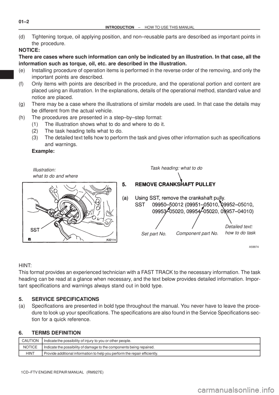
(h) The procedures are presented in a step±by±step format:
(1) The illustration shows what to do and where to do it.
(2) The task heading tells what to do.
(3) The detailed text tells how to perform the task and gives other information such as specifications
and warnings.
Example:
HINT:
This format provides an experienced technician with a FAST TRACK to the necessary information. The task
heading can be read at a glance when necessary, and the text below provides detailed information. Impor-
tant specifications and warnings always stand out in bold type.
5. SERVICE SPECIFICATIONS
(a) Specifications are presented in bold type throughout the manual. You never have to leave the proce-
dure to look up your specifications. The specifications are also found in the Service Specifications sec-
tion for a quick reference.
6. TERMS DEFINITION
CAUTIONIndicate the possibility of injury to you or other people.
NOTICEIndicate the possibility of damage to the components being repaired.
HINTProvide additional information to help you perform the repair efficiently.
Page 3 of 136
± INTRODUCTIONHOW TO USE THIS MANUAL
01±3
1CD±FTV ENGINE REPAIR MANUAL (RM927E)
7. SI UNIT
(a) The UNITS given in this manual are primarily expressed according to the SI UNIT (International Sys-
tem of Unit), and alternately expressed in the metric system and in the English System.
Example:
Torque: 30 N�m (310 kgf�cm, 22 ft�lbf)
Page 5 of 136

L1 L2
D02612
L2 L1
D01201
L2 L1
D01202
± INTRODUCTIONREPAIR INSTRUCTION
01±5
1CD±FTV ENGINE REPAIR MANUAL (RM927E)
NOTICE:
Do the torque checking with the lower limit value of the torque tolerance.
(4) Depending on the seal lock agent to apply, there may be a case where it is necessary to leave
it for a specified time until it hardens.
(b) Gaskets:
When necessary, use a sealer on gaskets to prevent leaks.
(c) Bolts, Nuts and Screws:
Carefully observe all specifications for bolt tightening torques. Always use a torque wrench.
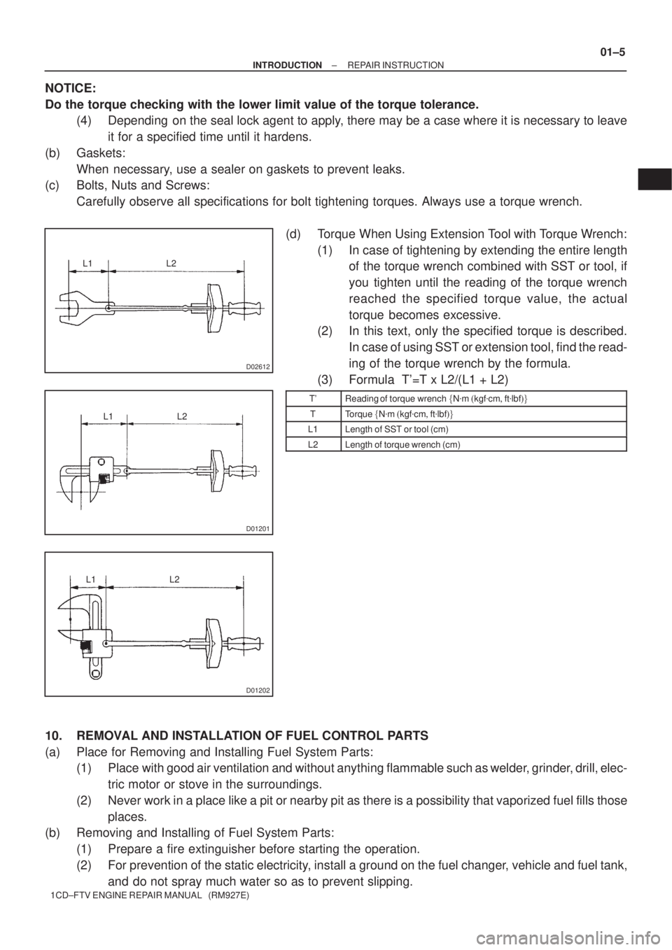
(d) Torque When Using Extension Tool with Torque Wrench:
(1) In case of tightening by extending the entire length
of the torque wrench combined with SST or tool, if
you tighten until the reading of the torque wrench
reached the specified torque value, the actual
torque becomes excessive.
(2) In this text, only the specified torque is described.
In case of using SST or extension tool, find the read-
ing of the torque wrench by the formula.
(3) Formula T'=T x L2/(L1 + L2)
T'Reading of torque wrench �N�m�kgf�cm�ft�lbf��
TTorque �N�m�kgf�cm�ft�lbf��
L1Length of SST or tool (cm)
L2Length of torque wrench (cm)
10. REMOVAL AND INSTALLATION OF FUEL CONTROL PARTS
(a) Place for Removing and Installing Fuel System Parts:
(1) Place with good air ventilation and without anything flammable such as welder, grinder, drill, elec-
tric motor or stove in the surroundings.
(2) Never work in a place like a pit or nearby pit as there is a possibility that vaporized fuel fills those
places.
(b) Removing and Installing of Fuel System Parts:
(1) Prepare a fire extinguisher before starting the operation.
(2) For prevention of the static electricity, install a ground on the fuel changer, vehicle and fuel tank,
and do not spray much water so as to prevent slipping.
Page 13 of 136

± INTRODUCTIONTERMS
01±13
1CD±FTV ENGINE REPAIR MANUAL (RM927E) HO2S
Heated Oxygen SensorHeated Oxygen Sensor (HO2S)
IACIdle Air ControlIdle Speed Control (ISC)
IATIntake Air TemperatureIntake or Inlet Air Temperature
ICMIgnition Control Module±
IFIIndirect Fuel InjectionIndirect Injection (IDL)
IFSInertia Fuel±Shutoff±
ISCIdle Speed Control±
KSKnock SensorKnock Sensor
MAFMass Air FlowAir Flow Meter
MAPManifold Absolute PressureManifold Pressure
Intake Vacuum
MCMixture Control
Electric Bleed Air Control Valve (EBCV)
Mixture Control Valve (MCV)
Electric Air Control Valve (EACV)
MDPManifold Differential Pressure±
MFIMultiport Fuel InjectionElectronic Fuel Injection (EFI)
MILMalfunction Indicator LampCheck Engine Lamp
MSTManifold Surface Temperature±
MVZManifold Vacuum Zone±
NVRAMNon±Volatile Random Access Memory±
O2SOxygen SensorOxygen Sensor, O2 Sensor (O2S)
OBDOn±Board DiagnosticOn±Board Diagnostic System (OBD)
OCOxidation Catalytic ConverterOxidation Catalyst Convert (OC), CCo
OPOpen LoopOpen Loop
PAIRPulsed Secondary Air InjectionAir Suction (AS)
PCMPowertrain Control Module±
PNPPark/Neutral Position±
PROMProgrammable Read Only Memory±
PSPPower Steering Pressure±
PTOXPeriodic Trap OxidizerDiesel Particulate Filter (DPF)
Diesel Particulate Trap (DPT)
RAMRandom Access MemoryRandom Access Memory (RAM)
RMRelay Module±
ROMRead Only MemoryRead Only Memory (ROM)
RPMEngine SpeedEngine Speed
SCSuperchargerSupercharger
SCBSupercharger BypassE±ABV
SFISequential Multiport Fuel InjectionElectronic Fuel Injection (EFI), Sequential Injection
SPLSmoke Puff Limiter±
SRIService Reminder Indicator±
SRTSystem Readiness Test±
STScan Tool±
TBThrottle BodyThrottle Body
TBIThrottle Body Fuel InjectionSingle Point Injection
Central Fuel Injection (Ci)
TCTurbochargerTurbocharger
TCCTorque Converter ClutchTorque Converter
Page 15 of 136
0214R±01
± PREPARATIONINTAKE
02±1
1CD±FTV ENGINE REPAIR MANUAL (RM927E)
INTAKE
PREPARATION
SST
09350±32014TOYOTA Automatic Transmission
Tool SetTURBOCHARGER
ASSEMBLY(1CD±FTV)
(09351±32070)No.2 Piston Spring CompressorTURBOCHARGER
ASSEMBLY(1CD±FTV)
09992±00242Turbocharger Pressure GaugeTURBOCHARGER
ASSEMBLY(1CD±FTV)
09992±00600Crank Type SpindleTURBOCHARGER
ASSEMBLY(1CD±FTV)
Recomended Tools
09042±00010Torx Socket T30TURBOCHARGER
ASSEMBLY(1CD±FTV)
SSM
08826±00080Seal Packing Black or equivalent
(FIPG)TURBOCHARGER
ASSEMBLY(1CD±FTV)
Equipment
Dial indicator
Torque wrench
Protractor
Steel square
Page 18 of 136
02±4
± PREPARATIONENGINE MECHANICAL
1CD±FTV ENGINE REPAIR MANUAL (RM927E)
(09962±01000)Variable Pin Wrench Arm AssyPARTIAL ENGINE ASSY(1CD±FTV)
(09963±01000)Pin 10PARTIAL ENGINE ASSY(1CD±FTV)
09992±00242Turbocharger Pressure GaugePARTIAL ENGINE ASSY(1CD±FTV)
SSM
08826±00080Seal Packing Black or equivalent
(FIPG)CYLINDER HEAD ASSY(1CD±FTV)
PARTIAL ENGINE ASSY(1CD±FTV)
08826±00100ºSeal Packing 1282B,º
THREE BOND 1282B or equivalent
(FIPG)PARTIAL ENGINE ASSY(1CD±FTV)
08833±00070ºAdhesive 1324,º
THREE BOND 1324 or equivalentCYLINDER HEAD ASSY(1CD±FTV)
CYLINDER BLOCK(1CD±FTV)
Equipment
V±block
Piston ring compressor
Piston ring expander
Valve seat cutter
Hexagon wrench (6 mm)
Hexagon wrench (8 mm)
Connecting rod aligner
Cylinder gauge
Dial indicator
Feeler gauge
Micrometer
Precision straight edge
Steel square
Torque wrench
Vernier calipers
Dial indicator with magnetic base
Slide calipers
Wooden block
Spring tester
Plastigage
Heater
Page 21 of 136
± PREPARATIONSTARTING & CHARGING
02±7
1CD±FTV ENGINE REPAIR MANUAL (RM927E)
(09083±00350)AC/DC 400 A ProbeSTARTER ASSY(2.2KW)(1CD±FTV)
Equipment
V±block
Feeler gauge
Ohmmeter
Torque wrench
Vernier calipers
Dial indicator with magnetic base