Page 23 of 136

SPECIFIED TORQUE FOR STANDARD BOLTS
Specified torque
ClassDiameter
mm
Pitch
mmHexagon head boltHexagon f")
030KQ±01
03±2
± SERVICE SPECIFICATIONSSTANDARD BOLT
1CD±FTV ENGINE REPAIR MANUAL (RM927E)
SPECIFIED TORQUE FOR STANDARD BOLTS
Specified torque
ClassDiameter
mm
Pitch
mmHexagon head boltHexagon flange boltmmmmN´mkgf´cmft´lbfN´mkgf´cmft´lbf
4T
6
8
10
12
14
161
1.25
1.25
1.25
1.5
1.55
12.5
26
47
74
11 555
130
260
480
760
1,15048 in.´lbf
9
19
35
55
836
14
29
53
84
±60
145
290
540
850
±52 in.´lbf
10
21
39
61
±
5T
6
8
10
12
14
161
1.25
1.25
1.25
1.5
1.56.5
15.5
32
59
91
14065
160
330
600
930
1,40056 in.´lbf
12
24
43
67
1017.5
17.5
36
65
100
±75
175
360
670
1,050
±65 in.´lbf
13
26
48
76
±
6T
6
8
10
12
14
161
1.25
1.25
1.25
1.5
1.58
19
39
71
11 0
17080
195
400
730
1,100
1,75069 in.´lbf
14
29
53
80
1279
21
44
80
125
±90
210
440
810
1,250
±78 in.´lbf
15
32
59
90
±
7T
6
8
10
12
14
161
1.25
1.25
1.25
1.5
1.510.5
25
52
95
145
23011 0
260
530
970
1,500
2,3008
19
38
70
108
16612
28
58
105
165
±120
290
590
1,050
1,700
±9
21
43
76
123
±
8T
8
10
121.25
1.25
1.2529
61
11 0300
620
1,10022
45
8033
68
120330
690
1,25024
50
90
9T
8
10
121.25
1.25
1.2534
70
125340
710
1,30025
51
9437
78
140380
790
1,45027
57
105
10T
8
10
121.25
1.25
1.2538
78
140390
800
1,45028
58
10542
88
155430
890
1,60031
64
11 6
11 T
8
10
121.25
1.25
1.2542
87
155430
890
1,60031
64
11 647
97
175480
990
1,80035
72
130
Page 26 of 136
030KT±01
± SERVICE SPECIFICATIONSINTAKE
03±5
1CD±FTV ENGINE REPAIR MANUAL (RM927E)
TORQUE SPECIFICATION
Part tightenedN´mkgf´cmft´lbf
V Band8.38574 in.´lbf
Compressor housing x Bearing housing4.74842 in.´lbf
Turbocharger actuator x Compressor housing7.88069 in.´lbf
Compressor inlet elbow x Compressor housing2323517
Page 29 of 136

TORQUE SPECIFICATION
Part TightenedN �mkgf �cmft �lbf
Cylinder block water drain cock x Cylinder bl")
0300P±05
03±8
±
SERVICE SPECIFICATIONS ENGINE MECHANICAL
1CD±FTV ENGINE REPAIR MANUAL (RM927E)
TORQUE SPECIFICATION
Part TightenedN �mkgf �cmft �lbf
Cylinder block water drain cock x Cylinder block2929121
Oil check valve x Cylinder block3031022
Oil pump x Cylinder block3132023
Oil pan x Cylinder block For 10 mm head bolt and nut
For 12 mm head bolt
For 14 mm head bolt11
21
4211 2
210
4298.0 15
31
Oil strainer x Cylinder block For bolt For nut21
13210
13515
10
Oil pan No.2 x Cylinder block121209.0
Cylinder head x Cylinder block 1st 2nd3rd
4th45
Turn 90 �
Turn 90 �
Turn 90 �460
Turn 90 �
Turn 90 �
Turn 90 �33
Turn 90 �
Turn 90 �
Turn 90 �
Camshaft bearing cap x Cylinder head2020415
Water pump x Cylinder block3132023
Camshaft oil seal retainer x Cylinder head8.89078 in.�lbf
Timing belt idler Sub assy No.2 x Oil pump4747534
Timing belt idler No. 1 x Cylinder head3535025
Camshaft timing pulley x Camshaft8889965
Nozzle holder clamp x Cylinder head2727520
Nozzle leakage pipe x Cylinder head Hollow screw
Union bolt18
22184
22413
16
Over flow screw x Plug9.81007.0
Check valve x Cylinder head2121415
Cylinder head cover x Cylinder head1313510
Taper screw plug No.1 x Cylinder head2525518
Cylinder head stud bolt (See Page 14±23) Bolt A Bolt B
Bolt C8.8
12
8.890
120 9078 in. �lbf
9.0
78 in. �lbf
Connecting rod cap x Connecting rod 1st
2nd30
Turn 90 �306
Turn 90 �22
Turn 90 �
Crankshaft bearing cap x Cylinder block11 51,17385
Cylinder block oil orifice x Cylinder block9.09278 in.�lbf
Oil nozzle No.1 x Cylinder block7.47667 in. �lbf
Page 32 of 136

TORQUE SPECIFICATION
Part TightenedN�mkgf�cmft�lbf
Starter assy (1.4kw)
Commutator end frame assy")
0300R±04
± SERVICE SPECIFICATIONSSTARTING & CHARGING
03±11
1CD±FTV ENGINE REPAIR MANUAL (RM927E)
TORQUE SPECIFICATION
Part TightenedN�mkgf�cmft�lbf
Starter assy (1.4kw)
Commutator end frame assy x Starter yoke
Starter housing x Magnetic switch
Filed frame x Armature assembly
Lead wire x Terminal C of starter
1.5
5.9
5.9
5.915
60
60
6013 in.�lbf
52 in.�lbf
52 in.�lbf
52 in.�lbf
Starter assy (2.0kw)
Commutator end frame assy x Starter housing
Commutator end frame cover x Commutator end frame assy
Starter housing x Magnet Starter Switch
Lead wire x Terminal C of starter
6.5
1.7
5.0
8.066
17
51
8258 in.�lbf
15 in.�lbf
44 in.�lbf
71 in.�lbf
Starter assy (2.2kw)
Starter housing x Magnetic switch
Filed frame x Armature assembly
Lead wire x Terminal C of starter
9.3
12.7
5.995
130
6082 in.�lbf
9.0
52 in.�lbf
Generator (90A)
Rectifire end frame x Drive end frame Nut A
Nut B
Rectifire holder x Rectifire end frame
Voltage regulator x Rectifire holder
Brush holder x Rectifier holder
Rear end cover x Rectifier end frame Nut
Bolt
Generator pulley x Rotor
4.5
5.4
2.9
3.9
2.0
4.4
3.9
11146
55
30
40
20
45
39
1,13339 in.�lbf
47 in.�lbf
26 in.�lbf
35 in.�lbf
18 in.�lbf
39 in.�lbf
35 in.�lbf
82
Generator assy (130 A)
Rectifire end frame x Drive end frame
Generator pulley x Rotor
Brush holder x Rectifire end frame
Rear end cover x Rectifire holder
5.8
111
1.8
4.659
1,133
18
4751 in.�lbf
82
16 in.�lbf
41 in.�lbf
Page 33 of 136
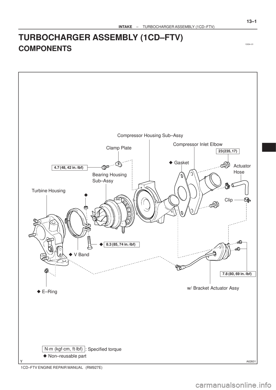
13034±01
A62601
Turbine HousingBearing Housing
Sub±AssyClamp PlateCompressor Housing Sub±Assy
Compressor Inlet Elbow
Actuator
Hose
Clip
w/ Bracket Actuator Assy � V Band� Gasket
� E±Ring
4.7 (48, 42 in.´lbf)
�
7.8 (80, 69 in.´lbf)
�
23 (235, 17)
� Non±reusable part
N´m (kgf´cm, ft´lbf)
: Specified torque
8.3 (85, 74 in.´lbf)
± INTAKETURBOCHARGER ASSEMBLY (1CD±FTV)
13±1
1CD±FTV ENGINE REPAIR MANUAL (RM927E)
TURBOCHARGER ASSEMBLY (1CD±FTV)
COMPONENTS
Page 39 of 136

13±7
1CD±FTV ENGINE REPAIR MANUAL (RM927E)
(e)")
A62448
Matchmarks
B08239
Approx. 38�
A62453
60�3 4 5
2
1 60�
A62454
Seal Width
0.1 ± 0.2 mmSeal
Packing
± INTAKETURBOCHARGER ASSEMBLY (1CD±FTV)
13±7
1CD±FTV ENGINE REPAIR MANUAL (RM927E)
(e) Align the matchmarks on the new V band, turbine housing
and bearing housing, and temporarily torque with a new
bolt and nut.
Torque: 8.3 N�m (85 kgf�cm, 74 in.�lbf)
HINT:
When the marks are erased, make the matching openings meet
at the position shown in the illustration.
(f) Using a brass bar and hammer, hit 2 or 3 times lightly at
each place in order of 1 through 5.
(g) Torque the bolt and nut more.
Torque: 8.3 N�m (85 kgf�cm, 74 in.�lbf)
(h) Using a brass bar and hammer, hit 2 or 3 times lightly at
each place of 1 and 4.
(i) Torque the bolt and nut completely.
Torque: 8.3 N�m (85 kgf�cm, 74 in.�lbf)
9. INSTALL COMPRESSOR HOUSING SUB±ASSY
(a) In case of reusing the compressor housing and bearing
housing:
(1) Apply seal packing to the compressor housing as
shown in the illustration.
Seal packing: Part No. 08826±00080 or equivalent
NOTICE:
Avoid applying an excessive amount to the surface.
�Install a nozzle that has been cut to a 0.1 ± 0.2
mm (0.004 ± 0.008 in.) opening.
�Parts must be assembled within 7 minutes of
application. Otherwise the material must be
removed and reapplied.
�Immediately remove nozzle from the tube
and reinstall the cap.
Page 40 of 136

1CD±FTV ENGINE REPAIR MANUAL (RM927E)
(2) Align the matchmarks on the compressor h")
A62455
Matchmarks
A62456
Cut
Protractor
Steel Square49�
A62457
SST
13±8
± INTAKETURBOCHARGER ASSEMBLY (1CD±FTV)
1CD±FTV ENGINE REPAIR MANUAL (RM927E)
(2) Align the matchmarks on the compressor housing
and bearing housing, and install them.
NOTICE:
�Do not make the impeller wheel interfere with the
compressor housing.
�Check that the turbine shaft turns smoothly.
(3) Using a steel square and protractor, check the
installation angle of the outlet port of the compres-
sor housing shown in the illustration.
(4) Install the 5 clamp plates and bolts.
Torque: 4.7 N�m (48 kgf�cm, 42 in.�lbf)
(b) In case of using a new compressor housing and/or bear-
ing housing :
(1) Temporally install the compressor housing on the
bearing housing, make the installation angle of the
outlet port of the compressor housing meet at the
position shown in the illustration, and place the
matchmarks.
(2) Remove the compressor housing.
(3) The following procedure is the same as that of reus-
ing the compressor housing and/or bearing hous-
ing.
10. INSTALL W/BRACKET ACTUATOR ASSY
(a) Using a torx wrench (T30), install the actuator w/ bracket
to the compressor housing with the 2 screws.
Torque: 7.8 N�m (80 kgf�cm, 69 in.�lbf)
(b) Using SST, move the actuator push rod.
SST 09992±00242
NOTICE:
Never apply more than 197 kPa (2.01 kgf/cm
2, 28.5 psi) of
pressure on the actuator.
(c) Connect the actuator push rod to the waste gate valve link
with a new E±ring.
NOTICE:
Do not use a hammer, etc. to force the actuator push rod
onto the waste gate valve link.
(d) Remove the SST.
(e) Connect the actuator hose.
11. INSTALL COMPRESSOR INLET ELBOW
Torque: 23 N�m (235 kgf�cm, 17 ft�lbf)
Page 41 of 136

Camshaft Oil
Seal Retainer
� Nozzle Holder Seal
Nozzle Leakage
Pipe Assy
Nozzle H")
140L3±01
A62602
Cylinder Head
Cover Sub±AssyGasket
Camshaft
Sub±Assy No.2
Camshaft
Sub±Assy No.1
18 (184, 13)
Camshaft Oil
Seal Retainer
� Nozzle Holder Seal
Nozzle Leakage
Pipe Assy
Nozzle Holder Clamp � O±Ring
� Injection Nozzle Seat
� Fuel Injector
Back±Up Ring No. 1
13 (135, 10)
Washer
Camshaft Carrier
Camshaft Bearing Cap
20 (204, 15)
Injector Assy
8.8 (90, 78 in.´lbf)
See page 14±3
1st 45 (460, 33)
2nd Turn 90 �
3rd Turn 90 �
4th Turn 90 �
22 (224, 16)
27 (275, 20)
� Gasket
� Gasket
20 (204, 15)
� Cylinder Head Gasket
� Oil Seal Plate Washer
x 18
Cylinder Head
Sub±Assy
�
Nozzle Holder Gasket
� Non±reusable partN´m (kgf´cm, ft´lbf)
: Specified torque
Oil Filler Cap Sub±Assy
Plate Washer
Camshaft Timing Pulley
88 (899, 65)
35 (357, 26)
Timing Belt Idler Sub±Assy No. 1
Timing Belt Idler Sub±Assy No. 2
47 (475, 34)
Crankshaft Timing Pulley
±
ENGINE MECHANICAL PARTIAL ENGINE ASSY (1CD±FTV)
14±1
1CD±FTV ENGINE REPAIR MANUAL (RM927E)
PARTIAL ENGINE ASSY (1CD±FTV)
COMPONENTS

TORQUE SPECIFICATION
Part tightenedN´mkgf´cmft´lbf
V Band8.38574 in.´lbf
Compressor housing x Bearing housi")