Page 58 of 136
A57103
Plate Washer
Hexagon
Wrench
(8mm)
A62592
SST
B08252
B09792
Spring
Convex
14±18
± ENGINE MECHANICALPARTIAL ENGINE ASSY (1CD±FTV)
1CD±FTV ENGINE REPAIR MANUAL (RM927E)
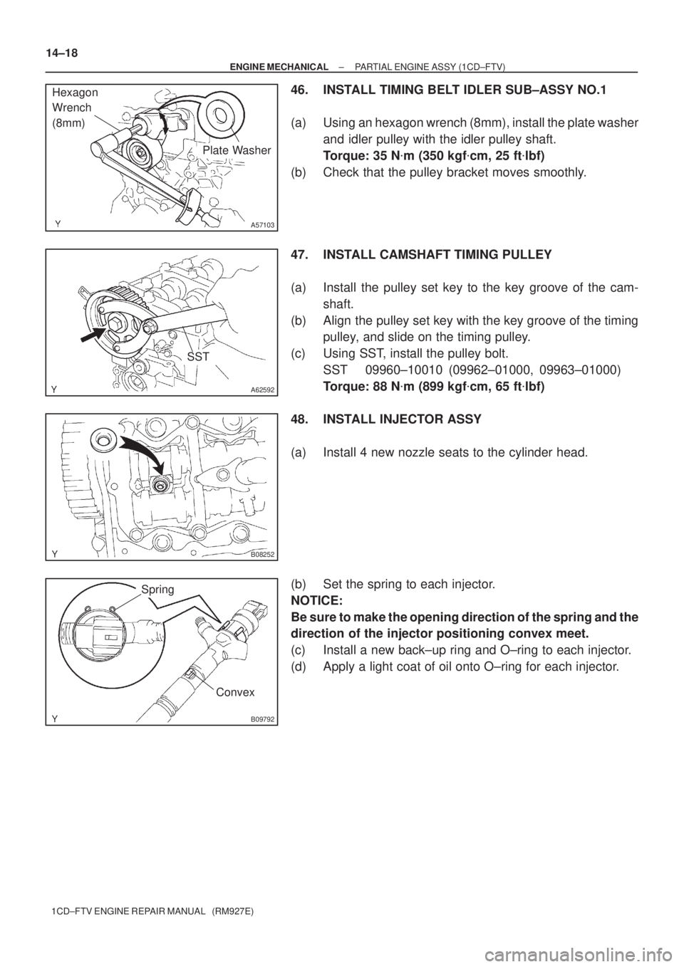
46. INSTALL TIMING BELT IDLER SUB±ASSY NO.1
(a) Using an hexagon wrench (8mm), install the plate washer
and idler pulley with the idler pulley shaft.
Torque: 35 N�m (350 kgf�cm, 25 ft�lbf)
(b) Check that the pulley bracket moves smoothly.
47. INSTALL CAMSHAFT TIMING PULLEY
(a) Install the pulley set key to the key groove of the cam-
shaft.
(b) Align the pulley set key with the key groove of the timing
pulley, and slide on the timing pulley.
(c) Using SST, install the pulley bolt.
SST 09960±10010 (09962±01000, 09963±01000)
Torque: 88 N�m (899 kgf�cm, 65 ft�lbf)
48. INSTALL INJECTOR ASSY
(a) Install 4 new nozzle seats to the cylinder head.
(b) Set the spring to each injector.
NOTICE:
Be sure to make the opening direction of the spring and the
direction of the injector positioning convex meet.
(c) Install a new back±up ring and O±ring to each injector.
(d) Apply a light coat of oil onto O±ring for each injector.
Page 59 of 136
B09793
Convex
Concave
B08249
Upward
B08253
± ENGINE MECHANICALPARTIAL ENGINE ASSY (1CD±FTV)
14±19
1CD±FTV ENGINE REPAIR MANUAL (RM927E)
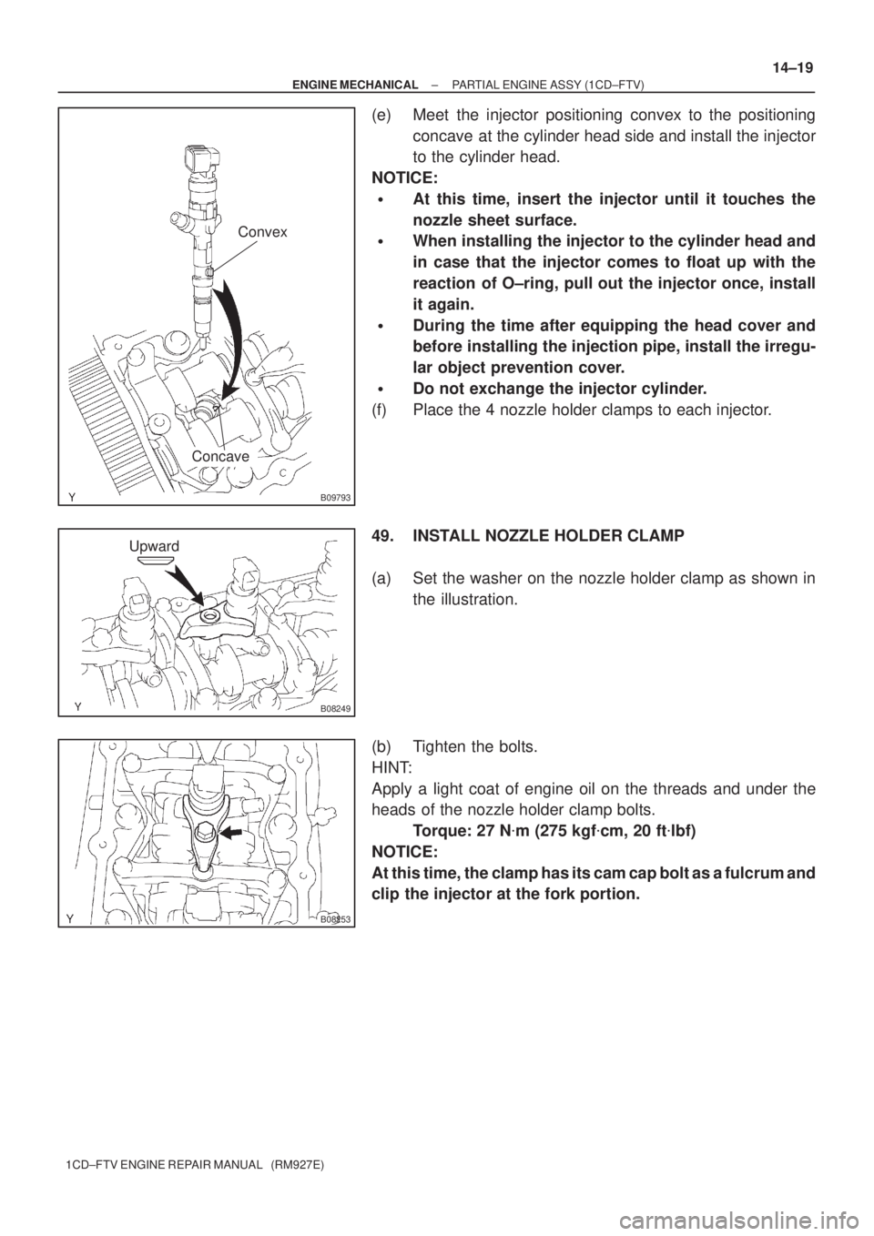
(e) Meet the injector positioning convex to the positioning
concave at the cylinder head side and install the injector
to the cylinder head.
NOTICE:
�At this time, insert the injector until it touches the
nozzle sheet surface.
�When installing the injector to the cylinder head and
in case that the injector comes to float up with the
reaction of O±ring, pull out the injector once, install
it again.
�During the time after equipping the head cover and
before installing the injection pipe, install the irregu-
lar object prevention cover.
�Do not exchange the injector cylinder.
(f) Place the 4 nozzle holder clamps to each injector.
49. INSTALL NOZZLE HOLDER CLAMP
(a) Set the washer on the nozzle holder clamp as shown in
the illustration.
(b) Tighten the bolts.
HINT:
Apply a light coat of engine oil on the threads and under the
heads of the nozzle holder clamp bolts.
Torque: 27 N�m (275 kgf�cm, 20 ft�lbf)
NOTICE:
At this time, the clamp has its cam cap bolt as a fulcrum and
clip the injector at the fork portion.
Page 60 of 136
90�
180�
B08307
B08311
B08312
Plug
GasketOverflow Screw
Ball Spring 14±20
± ENGINE MECHANICALPARTIAL ENGINE ASSY (1CD±FTV)
1CD±FTV ENGINE REPAIR MANUAL (RM927E)
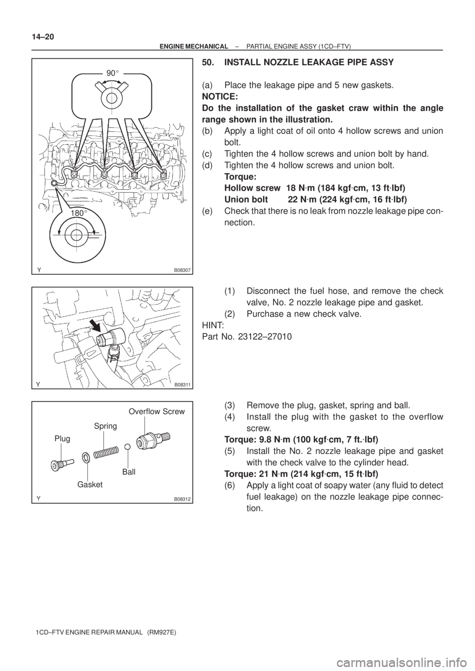
50. INSTALL NOZZLE LEAKAGE PIPE ASSY
(a) Place the leakage pipe and 5 new gaskets.
NOTICE:
Do the installation of the gasket craw within the angle
range shown in the illustration.
(b) Apply a light coat of oil onto 4 hollow screws and union
bolt.
(c) Tighten the 4 hollow screws and union bolt by hand.
(d) Tighten the 4 hollow screws and union bolt.
Torque:
Hollow screw 18 N�m (184 kgf�cm, 13 ft�lbf)
Union bolt 22 N�m (224 kgf�cm, 16 ft�lbf)
(e) Check that there is no leak from nozzle leakage pipe con-
nection.
(1) Disconnect the fuel hose, and remove the check
valve, No. 2 nozzle leakage pipe and gasket.
(2) Purchase a new check valve.
HINT:
Part No. 23122±27010
(3) Remove the plug, gasket, spring and ball.
(4) Install the plug with the gasket to the overflow
screw.
Torque: 9.8 N�m (100 kgf�cm, 7 ft.�lbf)
(5) Install the No. 2 nozzle leakage pipe and gasket
with the check valve to the cylinder head.
Torque: 21 N�m (214 kgf�cm, 15 ft�lbf)
(6) Apply a light coat of soapy water (any fluid to detect
fuel leakage) on the nozzle leakage pipe connec-
tion.
Page 61 of 136
A56050
New Gasket
Union Bolt
Hollow
Screw
SST
No. 2 Nozzle
Leakage Pipe
Check
Valve
New Gasket
B08328
Check
ValveNo. 2 Nozzle
Leakage Pipe
New Gasket
A09663
: Seal Packing
± ENGINE MECHANICALPARTIAL ENGINE ASSY (1CD±FTV)
14±21
1CD±FTV ENGINE REPAIR MANUAL (RM927E)
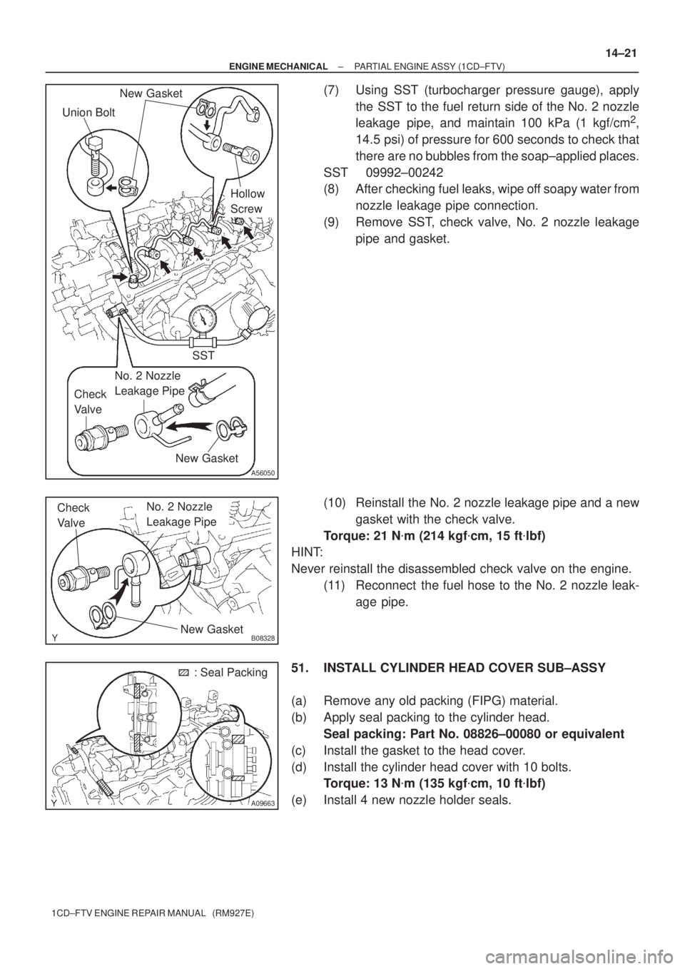
(7) Using SST (turbocharger pressure gauge), apply
the SST to the fuel return side of the No. 2 nozzle
leakage pipe, and maintain 100 kPa (1 kgf/cm
2,
14.5 psi) of pressure for 600 seconds to check that
there are no bubbles from the soap±applied places.
SST 09992±00242
(8) After checking fuel leaks, wipe off soapy water from
nozzle leakage pipe connection.
(9) Remove SST, check valve, No. 2 nozzle leakage
pipe and gasket.
(10) Reinstall the No. 2 nozzle leakage pipe and a new
gasket with the check valve.
Torque: 21 N�m (214 kgf�cm, 15 ft�lbf)
HINT:
Never reinstall the disassembled check valve on the engine.
(11) Reconnect the fuel hose to the No. 2 nozzle leak-
age pipe.
51. INSTALL CYLINDER HEAD COVER SUB±ASSY
(a) Remove any old packing (FIPG) material.
(b) Apply seal packing to the cylinder head.
Seal packing: Part No. 08826±00080 or equivalent
(c) Install the gasket to the head cover.
(d) Install the cylinder head cover with 10 bolts.
Torque: 13 N�m (135 kgf�cm, 10 ft�lbf)
(e) Install 4 new nozzle holder seals.
Page 72 of 136
A09550
A09551
A09552
A09546
Plastigage
A09557
14±32
± ENGINE MECHANICALCYLINDER HEAD ASSY (1CD±FTV)
1CD±FTV ENGINE REPAIR MANUAL (RM927E)
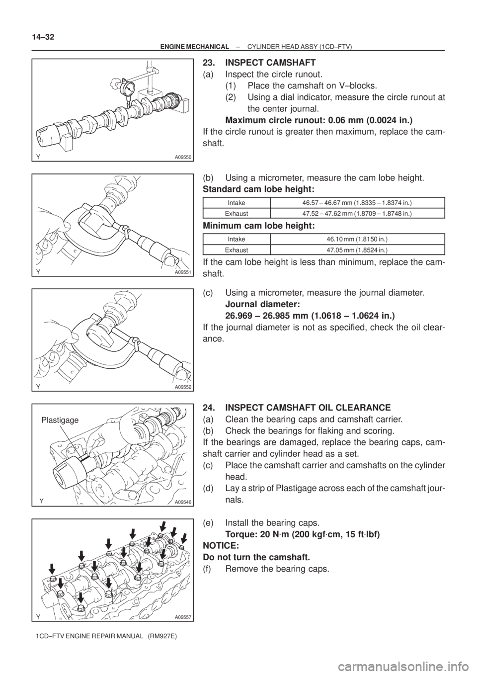
23. INSPECT CAMSHAFT
(a) Inspect the circle runout.
(1) Place the camshaft on V±blocks.
(2) Using a dial indicator, measure the circle runout at
the center journal.
Maximum circle runout: 0.06 mm (0.0024 in.)
If the circle runout is greater then maximum, replace the cam-
shaft.
(b) Using a micrometer, measure the cam lobe height.
Standard cam lobe height:
Intake46.57 ± 46.67 mm (1.8335 ± 1.8374 in.)
Exhaust47.52 ± 47.62 mm (1.8709 ± 1.8748 in.)
Minimum cam lobe height:
Intake46.10 mm (1.8150 in.)
Exhaust47.05 mm (1.8524 in.)
If the cam lobe height is less than minimum, replace the cam-
shaft.
(c) Using a micrometer, measure the journal diameter.
Journal diameter:
26.969 ± 26.985 mm (1.0618 ± 1.0624 in.)
If the journal diameter is not as specified, check the oil clear-
ance.
24. INSPECT CAMSHAFT OIL CLEARANCE
(a) Clean the bearing caps and camshaft carrier.
(b) Check the bearings for flaking and scoring.
If the bearings are damaged, replace the bearing caps, cam-
shaft carrier and cylinder head as a set.
(c) Place the camshaft carrier and camshafts on the cylinder
head.
(d) Lay a strip of Plastigage across each of the camshaft jour-
nals.
(e) Install the bearing caps.
Torque: 20 N�m (200 kgf�cm, 15 ft�lbf)
NOTICE:
Do not turn the camshaft.
(f) Remove the bearing caps.
Page 76 of 136
A56683
Intake Side: Rear Side:
Exhaust Side:A (M8)
B (M10)C (M8) 36 mm
64 mm34 mm
A62596
14±36
± ENGINE MECHANICALCYLINDER HEAD ASSY (1CD±FTV)
1CD±FTV ENGINE REPAIR MANUAL (RM927E)
30. INSTALL STUD BOLT
(a) Install the stud bolts as shown in the illustration.
Torque:
Bolt A 8.8N�m (90 kgf�cm, 78 in.�lbf)
Bolt B 12N�m (120 kgf�cm, 9 ft�lbf)
Bolt C 8.8N�m (90 kgf�cm, 78 in.�lbf)
31. INSTALL W/HEAD TAPER SCREW PLUG NO.1
(a) Apply adhesive to the plugs end.
Adhesive: Part No. 08833 ± 00070, THREE BOND 1324 or equivalent
(b) Using a hexagon wrench (6 mm), install the 3 plugs.
Torque:25N�m (255 kgf�cm, 18 ft�lbf)
SST 99999±70037
32. INSTALL SEMICIRCULAR PLUG
(a) Apply seal packing to the semi±circular plug grooves.
Seal packing: Part No. 08826 ± 00080 or equivalent
(b) Install the semi±circular plug to the cylinder head.
33. INSTALL VALVE SPRING SEAT PLATE WASHER
Page 79 of 136
140L6±01
A62605
No.1 Piston Ring
No.2 Piston Ring
Oil Ring
Connecting Rod
Connecting Rod
Bearing Connecting
Rod Cap Cylinder Block
Upper Crankshaft
Thrust Washer Crankshaft
Lower Crankshaft
Thrust Washer
Main Bearing CapLower Main Bearing
Upper Main Bearing Coil
� Non±reusable part
N´m (kgf´cm, ft´lbf)
Piston
: Specified torque
Connecting Rod
Bearing
See Page 14±40
1st 30 (306, 22)
2nd Turn 90
�
� Snap Ring
� Snap Ring
Cylinder Block
Oil Orifice
Sub±assy
Oil Nozzle No.1
115 (1,173, 85)
Piston Pin
9.0 (92, 78 in.´lbf)
7.4 (76, 67 in.´lbf)
±
ENGINE MECHANICAL CYLINDER BLOCK (1CD±FTV)
14±39
1CD±FTV ENGINE REPAIR MANUAL (RM927E)
CYLINDER BLOCK (1CD±FTV)
COMPONENTS
Page 81 of 136
A09514
Front Mark
(Protrusion)
A09493
90�
90�
A09490
Front
Painted Mark
A09495
± ENGINE MECHANICALCYLINDER BLOCK (1CD±FTV)
14±41
1CD±FTV ENGINE REPAIR MANUAL (RM927E)
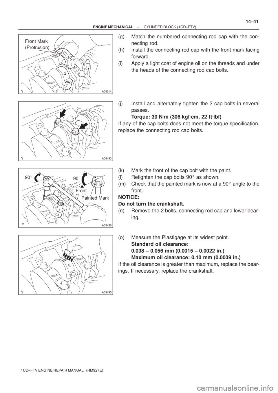
(g) Match the numbered connecting rod cap with the con-
necting rod.
(h) Install the connecting rod cap with the front mark facing
forward.
(i) Apply a light coat of engine oil on the threads and under
the heads of the connecting rod cap bolts.
(j) Install and alternately tighten the 2 cap bolts in several
passes.
Torque: 30 N�m (306 kgf�cm, 22 ft�lbf)
If any of the cap bolts does not meet the torque specification,
replace the connecting rod cap bolts.
(k) Mark the front of the cap bolt with the paint.
(l) Retighten the cap bolts 90� as shown.
(m) Check that the painted mark is now at a 90� angle to the
front.
NOTICE:
Do not turn the crankshaft.
(n) Remove the 2 bolts, connecting rod cap and lower bear-
ing.
(o) Measure the Plastigage at its widest point.
Standard oil clearance:
0.038 ± 0.056 mm (0.0015 ± 0.0022 in.)
Maximum oil clearance: 0.10 mm (0.0039 in.)
If the oil clearance is greater than maximum, replace the bear-
ings. If necessary, replace the crankshaft.