Page 118 of 136
190AH±01
A62713
Starter Yoke Assy
Starter Brush Holder AssyStarter Armature Assy
Drive Housing
Starter Clutch Sub±Assy Ball
Spring
Magnetic Switch
5.9 (60, 52 in.´lbf)
N´m (kgf´cm, ft´lbf)
: Specified torque
9.3 (95, 82 in.´lbf)
12.7 (130, 9.0 )
12.7 (130, 9.0 )
9.3 (95, 82 in.´lbf)
± STARTING & CHARGINGSTARTER ASSY(2.2KW) (1CD±FTV)
19±17
1CD±FTV ENGINE REPAIR MANUAL (RM927E)
STARTER ASSY(2.2KW) (1CD±FTV)
COMPONENTS
Page 123 of 136
A51212
A55483
A55646
A55635
B13607
19±22
± STARTING & CHARGINGSTARTER ASSY(2.2KW) (1CD±FTV)
1CD±FTV ENGINE REPAIR MANUAL (RM927E)
10. INSTALL STARTER ARMATURE ASSY
(a) Apply grease to the armature bearings.
(b) Using a press, press in armature.
11. INSTALL STARTER BRUSH HOLDER ASSY
(a) Align the claw of the brush holder with the claw groove of
the yoke.
(b) Place the brush on the yoke.
(c) Using a screwdriver, hold the brush spring back and con-
nect the brush into the brush holder. Connect the 4
brushes.
NOTICE:
Check that the positive (+) lead wires are not grounded.
12. INSTALL STARTER CLUTCH SUB±ASSY
(a) Apply grease to the ball.
(b) Insert the ball into the clutch shaft hole.
(c) Place the clutch on the drive housing.
(d) Install the drive housing to the magnetic switch with the
2 bolts.
Torque: 9.3 N�m (95 kgf�cm, 82 in.�lbf)
Page 124 of 136
A55647
A55633
± STARTING & CHARGINGSTARTER ASSY(2.2KW) (1CD±FTV)
19±23
1CD±FTV ENGINE REPAIR MANUAL (RM927E)
13. INSTALL STARTER YOKE ASSY
(a) Align the claws of the brush holder with the grooves of the
magnetic switch, and install the yoke and armature.
(b) Align the punch mark of the yoke with the line of the mag-
netic switch.
(c) Install the yoke and armature with the 2 through bolts.
Torque: 12.7 N�m (130 kgf�cm, 9 ft�lbf)
(d) Connect the lead wire to terminal C with the nut.
Torque: 5.9 N�m (60 kgf�cm, 52 in.�lbf)
Page 125 of 136
19094±02
A59147
PulleyDrive End FrameRotor
Alternator Washer
Rectifier End Frame
Voltage Regulator Brush Holder Cover
Brush HolderRear End Cover
N´m (kgf´cm, ft´lbf)
: Specified torque
111 (1125, 81)
Rectifier Holder
19±24
± STARTING & CHARGINGGENERATOR ASSY(90A) (1CD±FTV)
1CD±FTV ENGINE REPAIR MANUAL (RM927E)
GENERATOR ASSY(90A) (1CD±FTV)
COMPONENTS
Page 126 of 136
19095±02
A38024
A38025
SST 1 ± A
A38104
A38105
± STARTING & CHARGINGGENERATOR ASSY(90A) (1CD±FTV)
19±25
1CD±FTV ENGINE REPAIR MANUAL (RM927E)
OVERHAUL
1. REMOVE GENERATOR PULLEY
SST 09820±63010 (09820±06010, 09820±06020)
HINT:
SST1 ± A, B09820±06010
SST209820±06020
(a) Hold SST 1 ± A with a torque wrench, and tighten SST 1
± B clockwise to the specified torque.
Torque: 39 N�m (400 kgf�cm, 29 ft�lbf)
NOTICE:
Check that SST is secured to the rotor shaft.
(b) Mount SST 2 in a vise.
(c) Insert SST 1 ± A, B into SST 2, and attach the pulley nut
to SST 2.
(d) To loosen the pulley nut, turn SST 1 ± A in the direction
shown in the illustration.
NOTICE:
To prevent damage to the rotor shaft, do not loosen the
pulley nut more than one±half of a turn.
(e) Remove the alternator form SST 2.
(f) Turn SST 1 ± B, and remove SST 1 ± A, B.
(g) Remove the pulley nut and pulley.
Page 129 of 136

Length
P13535
17 mm
Socket
Wrench
A51920
Cord ClipA
B
A A
A64533
Inside
A51921
19±28
± STARTING & CHARGINGGENERATOR ASSY(90A) (1CD±FTV)
1CD±FTV ENGINE REPAIR MANUAL (RM927E)
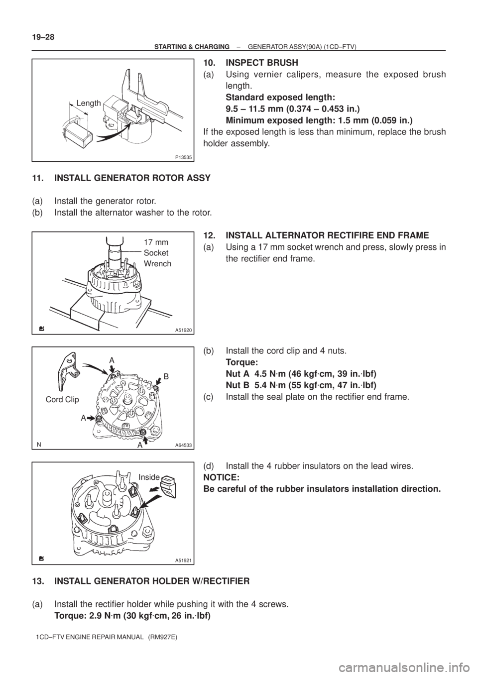
10. INSPECT BRUSH
(a) Using vernier calipers, measure the exposed brush
length.
Standard exposed length:
9.5 ± 11.5 mm (0.374 ± 0.453 in.)
Minimum exposed length: 1.5 mm (0.059 in.)
If the exposed length is less than minimum, replace the brush
holder assembly.
11. INSTALL GENERATOR ROTOR ASSY
(a) Install the generator rotor.
(b) Install the alternator washer to the rotor.
12. INSTALL ALTERNATOR RECTIFIRE END FRAME
(a) Using a 17 mm socket wrench and press, slowly press in
the rectifier end frame.
(b) Install the cord clip and 4 nuts.
Torque:
Nut A 4.5 N�m (46 kgf�cm, 39 in.�lbf)
Nut B 5.4 N�m (55 kgf�cm, 47 in.�lbf)
(c) Install the seal plate on the rectifier end frame.
(d) Install the 4 rubber insulators on the lead wires.
NOTICE:
Be careful of the rubber insulators installation direction.
13. INSTALL GENERATOR HOLDER W/RECTIFIER
(a) Install the rectifier holder while pushing it with the 4 screws.
Torque: 2.9 N�m (30 kgf�cm, 26 in.�lbf)
Page 130 of 136

Upward
A51919
A38024
± STARTING & CHARGINGGENERATOR ASSY(90A) (1CD±FTV)
19±29
1CD±FTV ENGINE REPAIR MANUAL (RM927E)
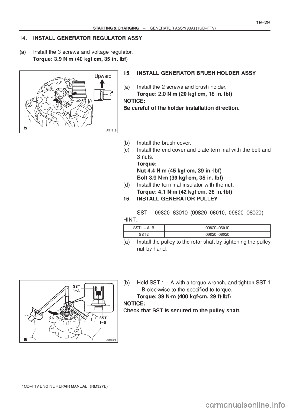
14. INSTALL GENERATOR REGULATOR ASSY
(a) Install the 3 screws and voltage regulator.
Torque: 3.9 N�m (40 kgf�cm, 35 in.�lbf)
15. INSTALL GENERATOR BRUSH HOLDER ASSY
(a) Install the 2 screws and brush holder.
Torque: 2.0 N�m (20 kgf�cm, 18 in.�lbf)
NOTICE:
Be careful of the holder installation direction.
(b) Install the brush cover.
(c) Install the end cover and plate terminal with the bolt and
3 nuts.
Torque:
Nut 4.4 N�m (45 kgf�cm, 39 in.�lbf)
Bolt 3.9 N�m (39 kgf�cm, 35 in.�lbf)
(d) Install the terminal insulator with the nut.
Torque: 4.1 N�m (42 kgf�cm, 36 in.�lbf)
16. INSTALL GENERATOR PULLEY
SST 09820±63010 (09820±06010, 09820±06020)
HINT:
SST1 ± A, B09820±06010
SST209820±06020
(a) Install the pulley to the rotor shaft by tightening the pulley
nut by hand.
(b) Hold SST 1 ± A with a torque wrench, and tighten SST 1
± B clockwise to the specified to torque.
Torque: 39 N�m (400 kgf�cm, 29 ft�lbf)
NOTICE:
Check that SST is secured to the pulley shaft.
Page 131 of 136
A38025
SST 1 ± A
A38126
A38105
19±30
± STARTING & CHARGINGGENERATOR ASSY(90A) (1CD±FTV)
1CD±FTV ENGINE REPAIR MANUAL (RM927E)
(c) Mount SST 2 in a vise.
(d) Insert SST 1 ± A, B into SST 2, and attach the pulley nut
to SST 2.
(e) Tighten the pulley nut, turn SST 1 ± A in the direction
shown in the illustration.
Torque: 111 N�m (1,125 kgf�cm, 81 ft�lbf)
(f) Remove the alternator form SST 2.
(g) Turn SST 1 ± B, and remove SST 1 ± A, B.
(h) Turn the pulley, and check that the pulley moves smooth-
ly.