Page 91 of 136
A09497
A09500
± ENGINE MECHANICALCYLINDER BLOCK (1CD±FTV)
14±51
1CD±FTV ENGINE REPAIR MANUAL (RM927E)
(h) Apply a light coat of engine oil on the threads and under
the heads of the main bearing cap bolts.
(i) Install and uniformly tighten the 10 bolts of the main bear-
ing cap in several passes.
Torque: 115 N�m (1,173 kgf�cm, 85 ft�lbf)
NOTICE:
Do not turn the crankshaft.
(j) Remove the bearing cap.
(k) Measure the Plastigage at its widest point.
Standard oil clearance:
0.026 ± 0.044 mm (0.0010 ± 0.0017 in.)
Maximum oil Clearance: 0.10 mm (0.0039 in.)
If the oil clearance is greater then maximum, replace the bear-
ings. If necessary, replace the crankshaft.
Page 96 of 136
A09473
Hexagon
Wrench (6 mm)
A09503
A56044
A56045
A09510Groove
14±56
± ENGINE MECHANICALCYLINDER BLOCK (1CD±FTV)
1CD±FTV ENGINE REPAIR MANUAL (RM927E)
25. INSTALL CYLINDER BLOCK OIL ORIFICE
(a) Using a hexagon wrench (6 mm), install the oil orifice.
Torque: 9.0 N�m (92 kgf�cm, 78 in.�lbf)
26. INSTALL SUB±ASSY OIL NOZZLE NO.1
(a) Install the oil nozzle with the bolt. Install the 4 oil nozzles.
Torque: 7.4 N�m (76 kgf�cm, 67 in.�lbf)
27. INSTALL CRANKSHAFT
(a) Install the bearing on the cylinder block and bearing cap.
HINT:
Upper bearings have an oil groove and oil holes; lower bearings
do not.
(1) Align the bearing claw with the claw groove of the
cylinder block, and push in the 5 upper bearings.
(2) Align the bearing claw with the claw groove of the
main bearing cap, and push in the 5 lower bearings.
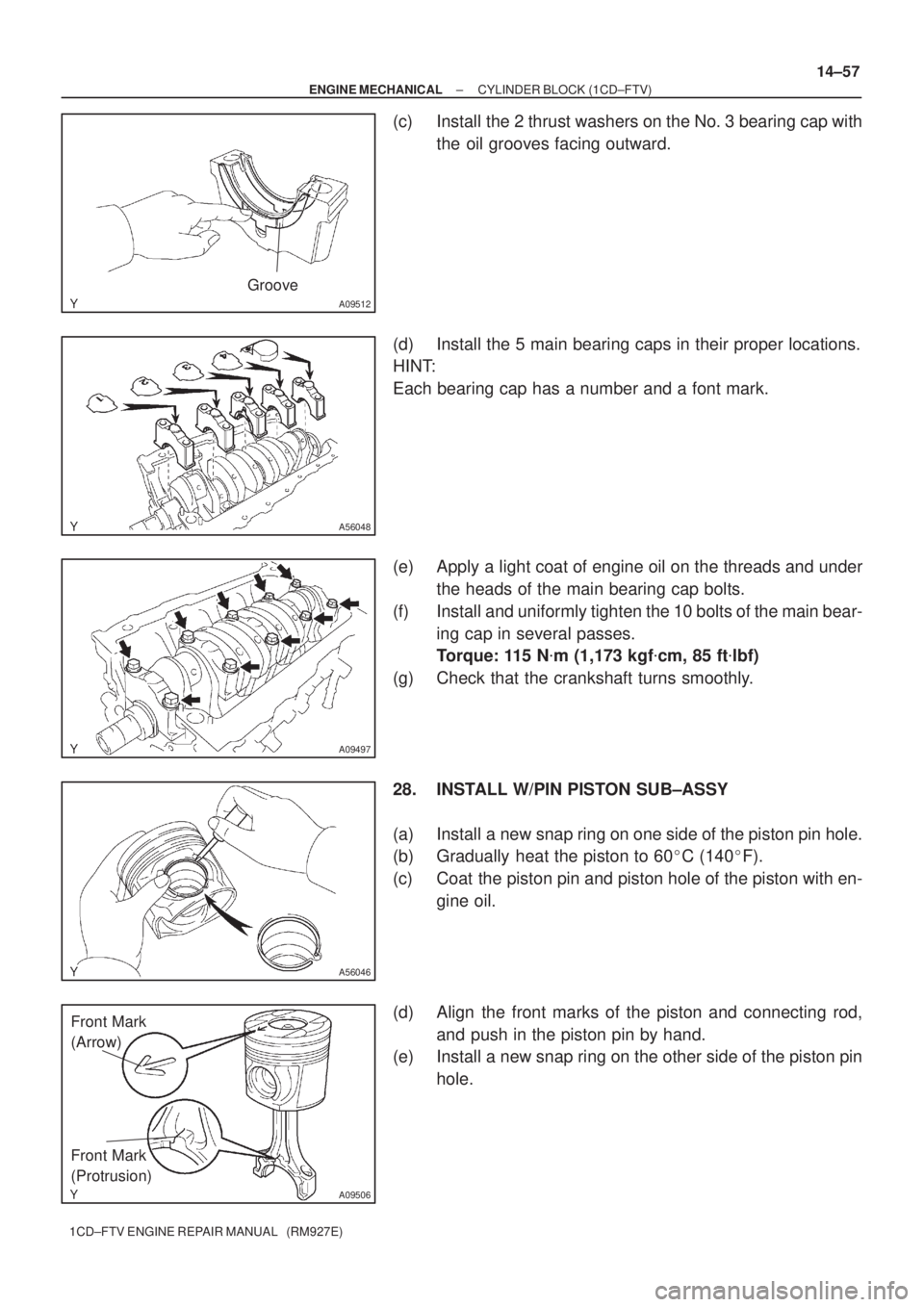
(b) Install the 2 thrust washers under the No. 3 journal posi-
tion of the cylinder block with the oil grooves facing out-
ward.
Page 97 of 136

A09512
Groove
A56048
A09497
A56046
A09506
Front Mark
(Arrow)
Front Mark
(Protrusion)
± ENGINE MECHANICALCYLINDER BLOCK (1CD±FTV)
14±57
1CD±FTV ENGINE REPAIR MANUAL (RM927E)
(c) Install the 2 thrust washers on the No. 3 bearing cap with
the oil grooves facing outward.
(d) Install the 5 main bearing caps in their proper locations.
HINT:
Each bearing cap has a number and a font mark.
(e) Apply a light coat of engine oil on the threads and under
the heads of the main bearing cap bolts.
(f) Install and uniformly tighten the 10 bolts of the main bear-
ing cap in several passes.
Torque: 115 N�m (1,173 kgf�cm, 85 ft�lbf)
(g) Check that the crankshaft turns smoothly.
28. INSTALL W/PIN PISTON SUB±ASSY
(a) Install a new snap ring on one side of the piston pin hole.
(b) Gradually heat the piston to 60�C (140�F).
(c) Coat the piston pin and piston hole of the piston with en-
gine oil.
(d) Align the front marks of the piston and connecting rod,
and push in the piston pin by hand.
(e) Install a new snap ring on the other side of the piston pin
hole.
Page 99 of 136

A09511
Front Mark
(Arrow)
Front
Push
A09514
Front Mark
(Protrusion)
A09493
90�
90�
A09490
Painted Mark
Front
± ENGINE MECHANICALCYLINDER BLOCK (1CD±FTV)
14±59
1CD±FTV ENGINE REPAIR MANUAL (RM927E)
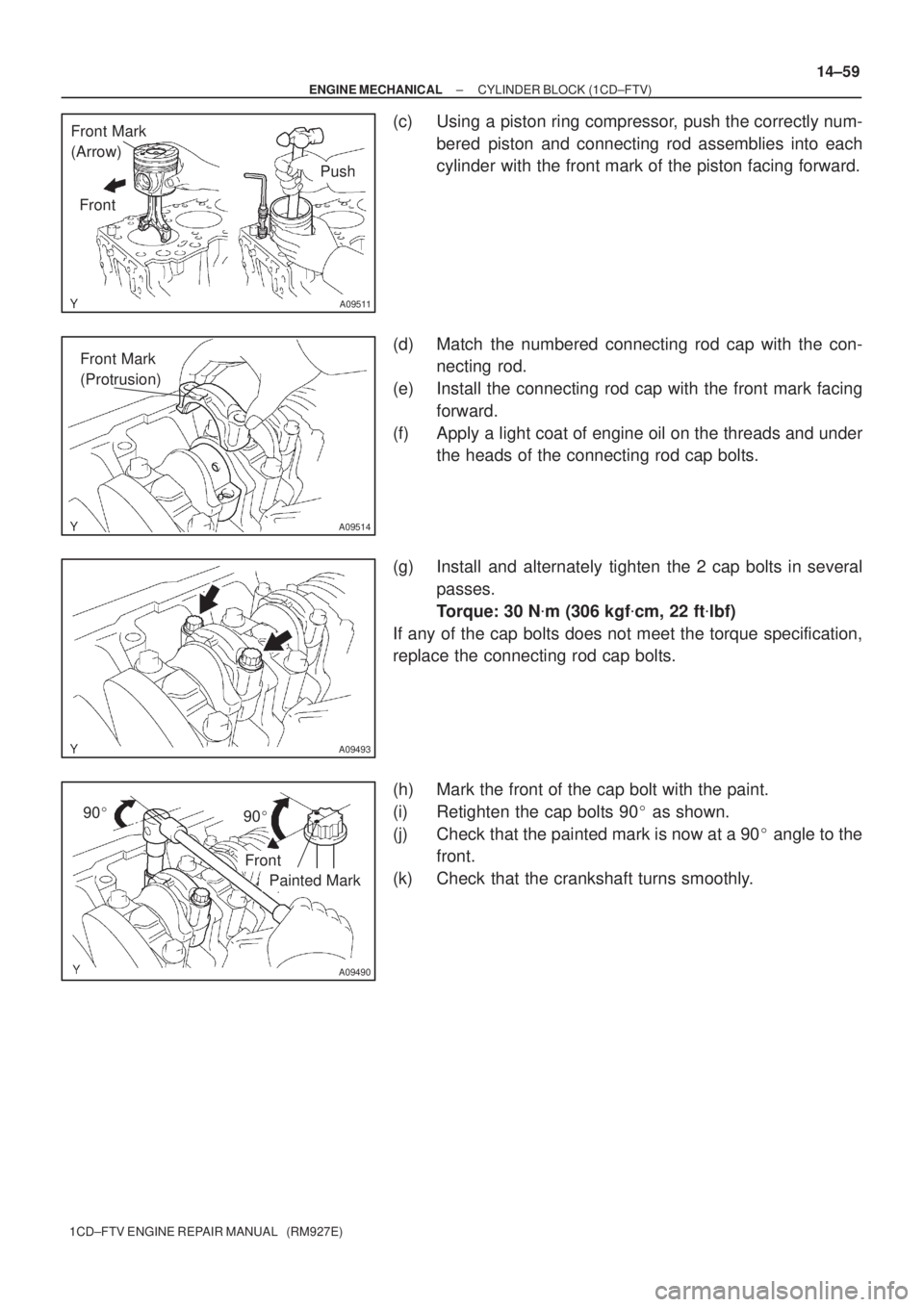
(c) Using a piston ring compressor, push the correctly num-
bered piston and connecting rod assemblies into each
cylinder with the front mark of the piston facing forward.
(d) Match the numbered connecting rod cap with the con-
necting rod.
(e) Install the connecting rod cap with the front mark facing
forward.
(f) Apply a light coat of engine oil on the threads and under
the heads of the connecting rod cap bolts.
(g) Install and alternately tighten the 2 cap bolts in several
passes.
Torque: 30 N�m (306 kgf�cm, 22 ft�lbf)
If any of the cap bolts does not meet the torque specification,
replace the connecting rod cap bolts.
(h) Mark the front of the cap bolt with the paint.
(i) Retighten the cap bolts 90� as shown.
(j) Check that the painted mark is now at a 90� angle to the
front.
(k) Check that the crankshaft turns smoothly.
Page 102 of 136
190AE±01
A62712
Starter Armature Assy
Starter Yoke Assy
Starter Brush Holder Assy
Rear End Frame Cover
Drive Housing
Starter Clutch Sub±Assy Ball
Spring
Magnetic Switch
N´m (kgf´cm, ft´lbf)
: Specified torque
5.9 (60, 52 in.´lbf)
5.9 (60, 52 in.´lbf)
5.9 (60, 52 in.´lbf)
± STARTING & CHARGINGSTARTER ASSY(1.4KW) (1CD±FTV)
19±1
1CD±FTV ENGINE REPAIR MANUAL (RM927E)
STARTER ASSY(1.4KW) (1CD±FTV)
COMPONENTS
Page 107 of 136
A55626
Terminal 50
Switch Body
A51226
A55614
A55627
19±6
± STARTING & CHARGINGSTARTER ASSY(1.4KW) (1CD±FTV)
1CD±FTV ENGINE REPAIR MANUAL (RM927E)
(b) Using an ohmmeter, check that there is continuity be-
tween terminal 50 and the switch body.
10. INSTALL STARTER ARMATURE ASSY
(a) Apply grease to the armature bearings and insert the armature into the yoke.
11. INSTALL STARTER BRUSH HOLDER ASSY
(a) Place the brush holder on the armature.
(b) Using a screwdriver, hold the brush spring back and con-
nect the brush into the brush holder. Connect the 4
brushes.
NOTICE:
Check that the positive (+) lead wires are not grounded.
(c) Install the end frame to the yoke with the 2 screws.
Torque: 1.5 N�m (15 kgf�cm, 13 in.�lbf)
12. INSTALL STARTER CLUTCH SUB±ASSY
(a) Apply grease to the ball.
(b) Insert the ball into the clutch shaft hole.
Page 108 of 136
A55612
A55611
A55628
A55610
± STARTING & CHARGINGSTARTER ASSY(1.4KW) (1CD±FTV)
19±7
1CD±FTV ENGINE REPAIR MANUAL (RM927E)
(c) Place the clutch on the drive housing.
(d) Install the drive housing to the magnetic switch with the
2 bolts.
Torque: 5.9 N�m (60 kgf�cm, 52 in.�lbf)
13. INSTALL STARTER YOKE ASSY
(a) Align the protrusion of the yoke with the cutout of the mag-
netic switch.
(b) Install the yoke and armature with the 2 through bolts.
Torque: 5.9 N�m (60 kgf�cm, 52 in.�lbf)
(c) Connect the lead wire to terminal C with the nut.
Torque: 5.9 N�m (60 kgf�cm, 52 in.�lbf)
Page 109 of 136
190AF±01
A62721
Return Spring
Plunger
Brush Retainer�
Starter Drive Housing
Assy Planet Carrier Shaft
Sub±assy
Starter
Commutator
End Fram
CoverRubber Cushion
Magnet Stater
Switch AssyStarter Pinion Drive Lever
Stop Collar
Snap Ring Starter Clutch
Sub±assy
Starter Yoke
Assy
Starter Commutator
End Frame Assy
Brush HolderThrust Washer
Starter Armature
Assy Brush Spring Lock Plate
� Non±reusable part
6.5 (66, 58 in.´lbf)
5.0 (51, 44 in.´lbf)
1.7 (17, 15 in.´lbf)
8.0 (82, 71 in.´lbf)
x 4
N´m (kgf´cm, ft´lbf) : Specified torque
19±8
± STARTING & CHARGINGSTARTER ASSY(2.0KW) (1CD±FTV)
1CD±FTV ENGINE REPAIR MANUAL (RM927E)
STARTER ASSY(2.0KW) (1CD±FTV)
COMPONENTS