Page 7 of 136

010B9±02
± INTRODUCTIONTERMS
01±7
1CD±FTV ENGINE REPAIR MANUAL (RM927E)
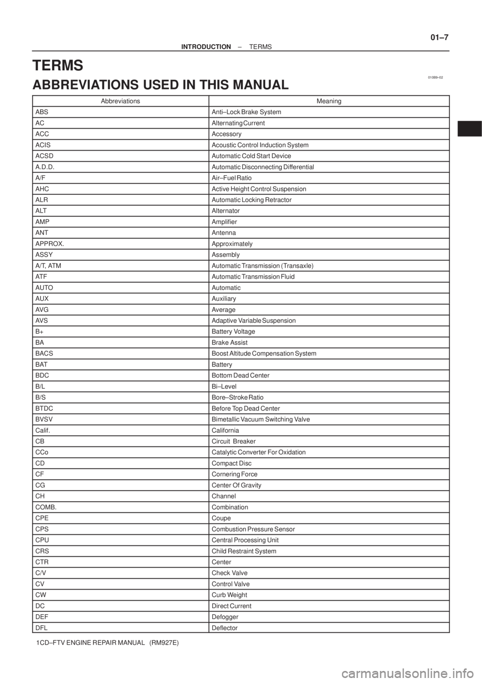
TERMS
ABBREVIATIONS USED IN THIS MANUAL
AbbreviationsMeaning
ABSAnti±Lock Brake System
ACAlternating Current
ACCAccessory
ACISAcoustic Control Induction System
ACSDAutomatic Cold Start Device
A.D.D.Automatic Disconnecting Differential
A/FAir±Fuel Ratio
AHCActive Height Control Suspension
ALRAutomatic Locking Retractor
ALTAlternator
AMPAmplifier
ANTAntenna
APPROX.Approximately
ASSYAssembly
A/T, ATMAutomatic Transmission (Transaxle)
AT FAutomatic Transmission Fluid
AUTOAutomatic
AUXAuxiliary
AV GAverage
AV SAdaptive Variable Suspension
B+Battery Voltage
BABrake Assist
BACSBoost Altitude Compensation System
BATBattery
BDCBottom Dead Center
B/LBi±Level
B/SBore±Stroke Ratio
BTDCBefore Top Dead Center
BVSVBimetallic Vacuum Switching Valve
Calif.California
CBCircuit Breaker
CCoCatalytic Converter For Oxidation
CDCompact Disc
CFCornering Force
CGCenter Of Gravity
CHChannel
COMB.Combination
CPECoupe
CPSCombustion Pressure Sensor
CPUCentral Processing Unit
CRSChild Restraint System
CTRCenter
C/VCheck Valve
CVControl Valve
CWCurb Weight
DCDirect Current
DEFDefogger
DFLDeflector
Page 9 of 136

± INTRODUCTIONTERMS
01±9
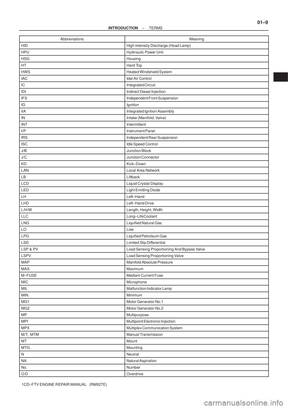
1CD±FTV ENGINE REPAIR MANUAL (RM927E)Abbreviations Meaning
HIDHigh Intensity Discharge (Head Lamp)
HPUHydrraulic Power Unit
HSGHousing
HTHard Top
HWSHeated Windshield System
IACIdel Air Control
ICIntegrated Circuit
IDIIndirect Diesel Injection
IFSIndependent Front Suspension
IGIgnition
IIAIntegrated Ignition Assembly
INIntake (Manifold, Valve)
INTIntermittent
I/PInstrument Panel
IRSIndependent Rear Suspension
ISCIdle Speed Control
J/BJunction Block
J/CJunction Connector
KDKick±Down
LANLocal Area Network
LBLiftback
LCDLiquid Crystal Display
LEDLight Emitting Diode
LHLeft±Hand
LHDLeft±Hand Drive
L/H/WLength, Height, Width
LLCLong±Life Coolant
LNGLiquified Natural Gas
LOLow
LPGLiquified Petroleum Gas
LSDLimited Slip Differential
LSP & PVLoad Sensing Proportioning And Bypass Valve
LSPVLoad Sensing Proportioning Valve
MAPManifold Absolute Pressure
MAX.Maximum
M±FUSEMediam Current Fuse
MICMicrophone
MILMalfunction Indicator Lamp
MIN.Minimum
MG1Motor Generator No.1
MG2Motor Generator No.2
MPMultipurpose
MPIMultipoint Electronic Injection
MPXMultiplex Communication System
M/T, MTMManual Transmission
MTMount
MTGMounting
NNeutral
NANatural Aspiration
No.Number
O/DOverdrive
Page 13 of 136

± INTRODUCTIONTERMS
01±13
1CD±FTV ENGINE REPAIR MANUAL (RM927E) HO2S
Heated Oxygen SensorHeated Oxygen Sensor (HO2S)
IACIdle Air ControlIdle Speed Control (ISC)
IATIntake Air TemperatureIntake or Inlet Air Temperature
ICMIgnition Control Module±
IFIIndirect Fuel InjectionIndirect Injection (IDL)
IFSInertia Fuel±Shutoff±
ISCIdle Speed Control±
KSKnock SensorKnock Sensor
MAFMass Air FlowAir Flow Meter
MAPManifold Absolute PressureManifold Pressure
Intake Vacuum
MCMixture Control
Electric Bleed Air Control Valve (EBCV)
Mixture Control Valve (MCV)
Electric Air Control Valve (EACV)
MDPManifold Differential Pressure±
MFIMultiport Fuel InjectionElectronic Fuel Injection (EFI)
MILMalfunction Indicator LampCheck Engine Lamp
MSTManifold Surface Temperature±
MVZManifold Vacuum Zone±
NVRAMNon±Volatile Random Access Memory±
O2SOxygen SensorOxygen Sensor, O2 Sensor (O2S)
OBDOn±Board DiagnosticOn±Board Diagnostic System (OBD)
OCOxidation Catalytic ConverterOxidation Catalyst Convert (OC), CCo
OPOpen LoopOpen Loop
PAIRPulsed Secondary Air InjectionAir Suction (AS)
PCMPowertrain Control Module±
PNPPark/Neutral Position±
PROMProgrammable Read Only Memory±
PSPPower Steering Pressure±
PTOXPeriodic Trap OxidizerDiesel Particulate Filter (DPF)
Diesel Particulate Trap (DPT)
RAMRandom Access MemoryRandom Access Memory (RAM)
RMRelay Module±
ROMRead Only MemoryRead Only Memory (ROM)
RPMEngine SpeedEngine Speed
SCSuperchargerSupercharger
SCBSupercharger BypassE±ABV
SFISequential Multiport Fuel InjectionElectronic Fuel Injection (EFI), Sequential Injection
SPLSmoke Puff Limiter±
SRIService Reminder Indicator±
SRTSystem Readiness Test±
STScan Tool±
TBThrottle BodyThrottle Body
TBIThrottle Body Fuel InjectionSingle Point Injection
Central Fuel Injection (Ci)
TCTurbochargerTurbocharger
TCCTorque Converter ClutchTorque Converter
Page 134 of 136
A57794
SST (B)
Turn
A57795
A57796
SST
A57797
A57798
± STARTING & CHARGINGGENERATOR ASSY(130A) (1CD±FTV)
19±33
1CD±FTV ENGINE REPAIR MANUAL (RM927E)
(d) Insert the 3 tabs of SST (B) into the 3 holes on the pulley.
(e) To loosen the pulley, turn SST (B) in the direction shown
in the illustration.
(f) Remove the alternator from SST.
(g) Remove the pulley from the rotor shaft.
3. REMOVE GENERATOR ROTOR ASSY
(a) Remove the 4 through bolts.
(b) Using SST, remove the coil assembly.
SST 09950±40011 (09951±04020, 09952±04010,
09953±04020, 09954±04010, 09955±04071,
09958±04011)
(c) Remove the alternator washer.
(d) Remove the rotor from the drive end frame.
4. INSPECT GENERATOR ROTOR ASSY
(a) Using an ohmmeter, check that there is continuity be-
tween the slip rings.
Standard resistance: 2.3 ± 2.7 � at 20�C (68�F)
(b) Using an ohmmeter, check that there is no continuity be-
tween the slip ring and rotor.
Page 136 of 136

A55650
SST (A)
SST (B)
A55651
Rotor Shaft
SST (A)
A57803
SST (B)
Turn
A57804
Upward
A55648
± STARTING & CHARGINGGENERATOR ASSY(130A) (1CD±FTV)
19±35
1CD±FTV ENGINE REPAIR MANUAL (RM927E)
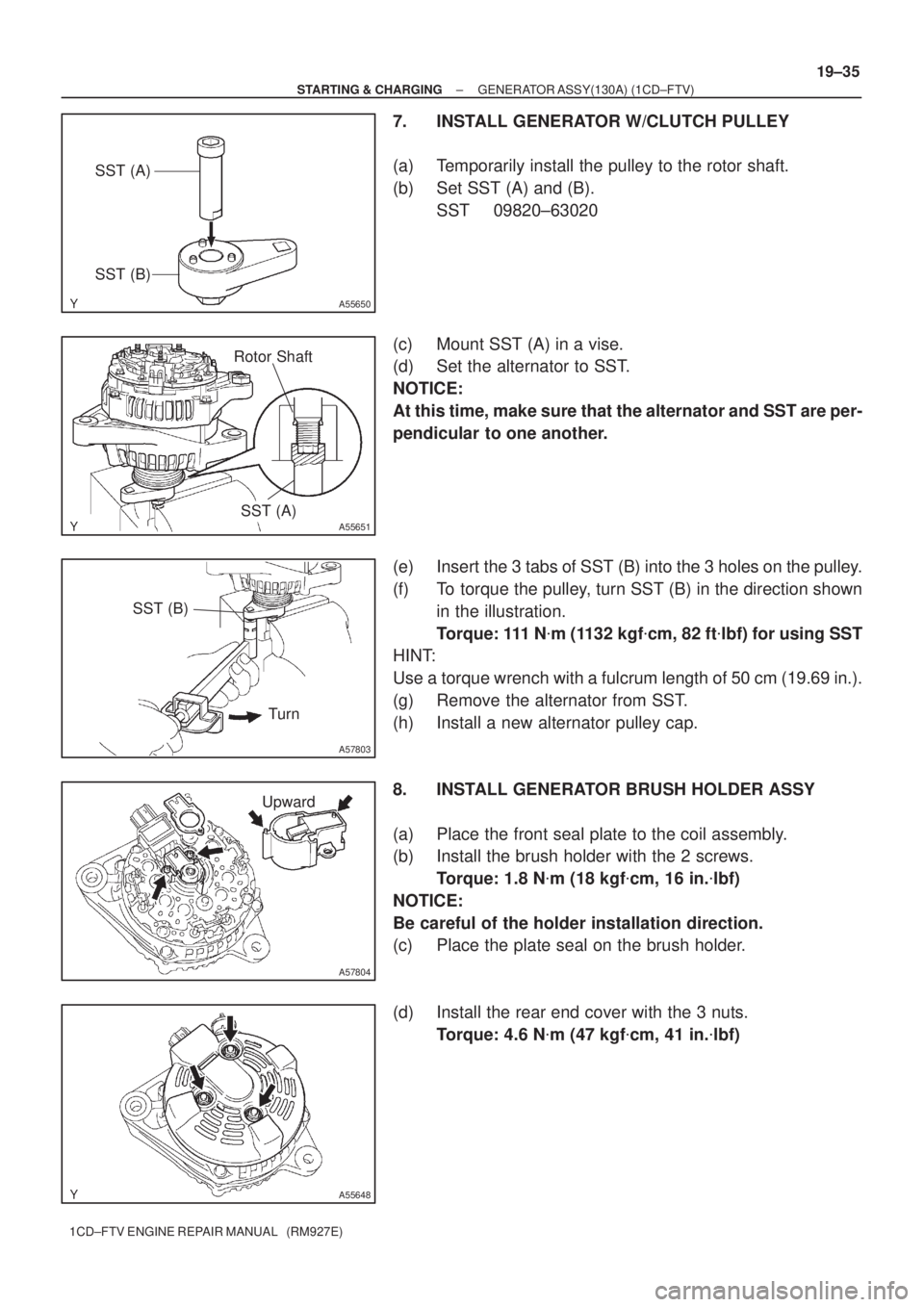
7. INSTALL GENERATOR W/CLUTCH PULLEY
(a) Temporarily install the pulley to the rotor shaft.
(b) Set SST (A) and (B).
SST 09820±63020
(c) Mount SST (A) in a vise.
(d) Set the alternator to SST.
NOTICE:
At this time, make sure that the alternator and SST are per-
pendicular to one another.
(e) Insert the 3 tabs of SST (B) into the 3 holes on the pulley.
(f) To torque the pulley, turn SST (B) in the direction shown
in the illustration.
Torque: 111 N�m (1132 kgf�cm, 82 ft�lbf) for using SST
HINT:
Use a torque wrench with a fulcrum length of 50 cm (19.69 in.).
(g) Remove the alternator from SST.
(h) Install a new alternator pulley cap.
8. INSTALL GENERATOR BRUSH HOLDER ASSY
(a) Place the front seal plate to the coil assembly.
(b) Install the brush holder with the 2 screws.
Torque: 1.8 N�m (18 kgf�cm, 16 in.�lbf)
NOTICE:
Be careful of the holder installation direction.
(c) Place the plate seal on the brush holder.
(d) Install the rear end cover with the 3 nuts.
Torque: 4.6 N�m (47 kgf�cm, 41 in.�lbf)