Page 1352 of 2870

EN(H4SO)-254
ENGINE (DIAGNOSTIC)
Diagnostic Procedure with Diagnostic Trouble Code (DTC)
Step Check Yes No
1 CHECK INPUT SIGNAL FROM ECM.
1) Turn the ignition switch to ON.
2) Measure the voltage between ECM and
chassis ground.
Connector & terminal
(B136) No. 18 (+) — Chassis ground (
−):Is the voltage more than 4.5 V? Go to step 2.Go to step 4.
2 CHECK INPUT SIGNAL FROM ECM.
Measure the voltage between ECM and chas-
sis ground.
Connector & terminal
(B136) No. 18 (+) — Chassis ground (
−):Is the voltage more than 10 V? Repair battery
short circuit in har-
ness between
ECM and TCM
connector.Go to step 3.
3 CHECK POOR CONTACT.
Check poor contact in ECM connector. Is there poor contact in ECM
connector?Repair the poor
contact in ECM
connector.Replace the ECM.
FU(H4SO)-44,
Engine Control
Module (ECM).>
4 CHECK HARNESS BETWEEN ECM AND
TCM CONNECTOR.
1) Turn the ignition switch to OFF.
2) Disconnect the connector from ECM and
TCM.
3) Measure the resistance of harness
between TCM and ECM connector.
Connector & terminal
(B136) No. 18 — (B56) No. 14:Is the resistance less than 1
Ω?Go to step 5.Repair the open
circuit in harness
between ECM and
TCM connector.
5 CHECK HARNESS BETWEEN ECM AND
TCM CONNECTOR.
Measure the resistance of harness between
ECM and chassis ground.
Connector & terminal
(B136) No. 18 — Chassis ground:Is the resistance more than 1
MΩ?Go to step 6.Repair ground
short circuit in har-
ness between
ECM and TCM
connector.
6 CHECK POOR CONTACT.
Check poor contact in TCM connector. Is there poor contact in TCM
connector?Repair poor con-
tact in TCM con-
nector.Replace the TCM.
Transmission Con-
trol Module
(TCM).>
Page 1354 of 2870

EN(H4SO)-256
ENGINE (DIAGNOSTIC)
General Diagnostic Table
*1: Check ignition coil & ignitor ASSY and spark plug.
*2: Indicate the symptom occurring only in cold temperatures.
*3: Ensure the secure installation.
*4: Check fuel injector, fuel pressure regulator and fuel filter.
*5: Inspect air leak in air intake system.
*6: Adjust the accelerator cable.
2. AUTOMATIC TRANSMISSION
NOTE:
Check general diagnostics table with non-conformity symptom for automatic transmission.
4AT(H4SO)-2, Basic Diagnostic Procedure.>
6. Surging1) Intake manifold pressure sensor
2) Intake air temperature sensor
3) Manifold absolute pressure sensor
4) Engine coolant temperature sensor (*2)
5) Crankshaft position sensor (*3)
6) Camshaft position sensor (*3)
7) Fuel injection parts (*4)
8) Throttle position sensor
9) Fuel pump and fuel pump relay
7. Spark knock1) Intake manifold pressure sensor
2) Intake air temperature sensor
3) Manifold absolute pressure sensor
4) Engine coolant temperature sensor
5) Knock sensor
6) Fuel injection parts (*4)
7) Fuel pump and fuel pump relay
8. After burning in exhaust system1) Intake manifold pressure sensor
2) Intake air temperature sensor
3) Manifold absolute pressure sensor
4) Engine coolant temperature sensor (*2)
5) Fuel injection parts (*4)
6) Fuel pump and fuel pump relay Symptom Problem parts
Page 1410 of 2870

FU(H4DOTC)-55
FUEL INJECTION (FUEL SYSTEM)
Fuel Tank
25.Fuel Tank
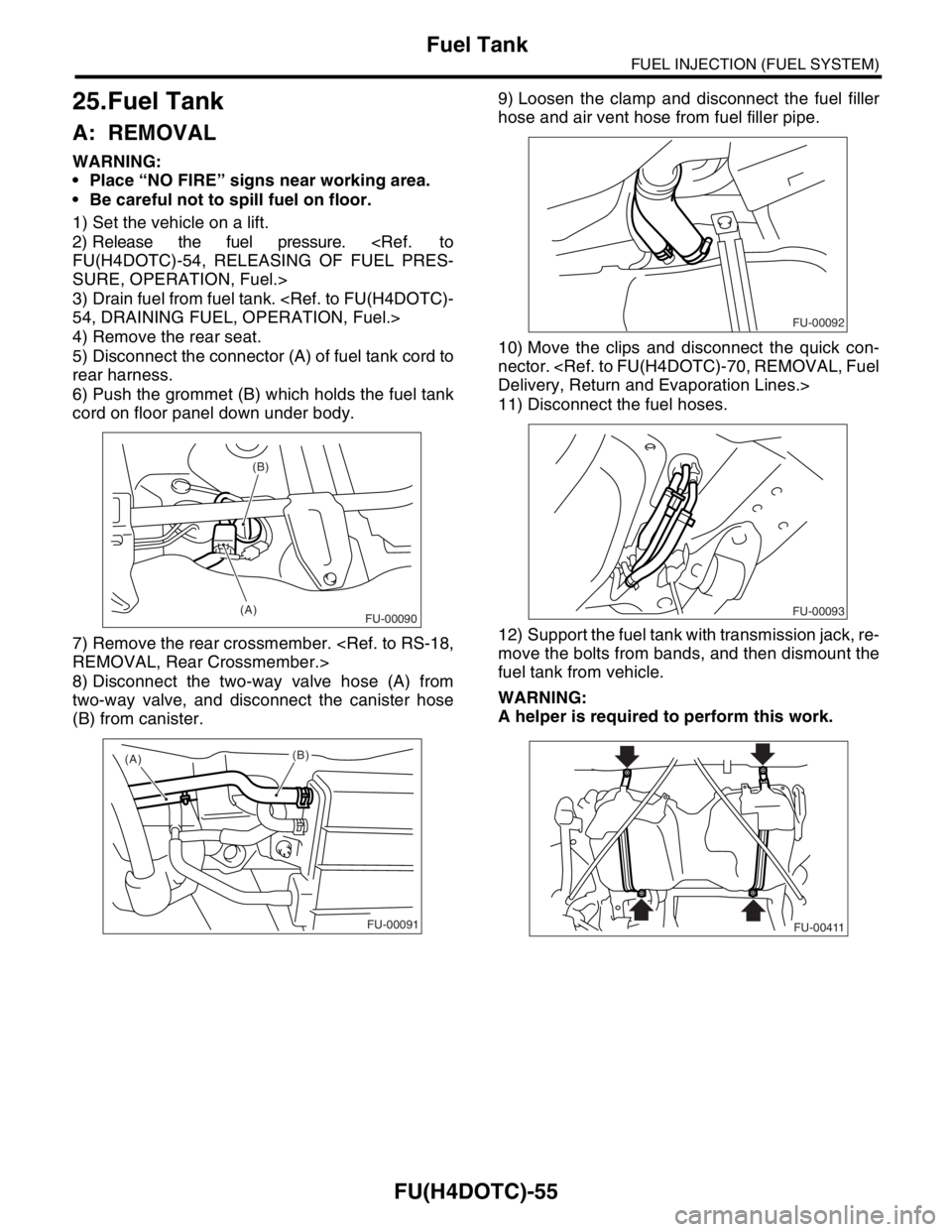
A: REMOVAL
WARNING:
Place “NO FIRE” signs near working area.
Be careful not to spill fuel on floor.
1) Set the vehicle on a lift.
2) Release the fuel pressure.
FU(H4DOTC)-54, RELEASING OF FUEL PRES-
SURE, OPERATION, Fuel.>
3) Drain fuel from fuel tank.
54, DRAINING FUEL, OPERATION, Fuel.>
4) Remove the rear seat.
5) Disconnect the connector (A) of fuel tank cord to
rear harness.
6) Push the grommet (B) which holds the fuel tank
cord on floor panel down under body.
7) Remove the rear crossmember.
REMOVAL, Rear Crossmember.>
8) Disconnect the two-way valve hose (A) from
two-way valve, and disconnect the canister hose
(B) from canister.9) Loosen the clamp and disconnect the fuel filler
hose and air vent hose from fuel filler pipe.
10) Move the clips and disconnect the quick con-
nector.
Delivery, Return and Evaporation Lines.>
11) Disconnect the fuel hoses.
12) Support the fuel tank with transmission jack, re-
move the bolts from bands, and then dismount the
fuel tank from vehicle.
WARNING:
A helper is required to perform this work.
(B)
(A)
FU-00090
(A)
(B)
FU-00091
FU-00092
FU-00093
FU-00411
Page 1411 of 2870
FU(H4DOTC)-56
FUEL INJECTION (FUEL SYSTEM)
Fuel Tank
B: INSTALLATION
1) Support the fuel tank with transmission jack and
push the fuel tank harness into access hole with
grommet.
2) Set the fuel tank and temporarily tighten the
bolts of fuel tank bands.
WARNING:
A helper is required to perform this work.
3) Connect the two-way valve hose (A) to two-way
valve and connect the canister hose (B) to canister.
4) Connect the fuel filler hose and air vent hose.5) Connect the fuel hoses, and secure them with
clips and quick connector.
71, INSTALLATION, Fuel Delivery, Return and
Evaporation Lines.>
6) Tighten the band mounting bolts.
Tightening torque:
33 N
⋅m (3.4 kgf-m, 24.3 ft-lb)
7) Install the rear crossmember.
INSTALLATION, Rear Crossmember.>
8) Connect the connector (A) to the fuel tank cord,
and plug the service hole with grommet (B).
9) Set the rear seat and floor mat.
FU-00411
(A)(B)
FU-00091
FU-00092
FU-00093
FU-00411
(B)
(A)
FU-00090
Page 1478 of 2870

ME(H4DOTC)-22
MECHANICAL
General Description
C: CAUTION
Wear working clothing, including a cap, protec-
tive goggles, and protective shoes during opera-
tion.
Remove contamination including dirt and corro-
sion before removal, installation or disassembly.
Keep the disassembled parts in order and pro-
tect them from dust or dirt.
Before removal, installation or disassembly, be
sure to clarify the failure. Avoid unnecessary re-
moval, installation, disassembly, and replacement.
Be careful not to burn yourself, because each
part in the vehicle is hot after running.
Be sure to tighten fasteners including bolts and
nuts to the specified torque.
Place shop jacks or rigid racks at the specified
points.
Before disconnecting electrical connectors of
sensors or units, be sure to disconnect the ground
cable from battery.
All parts should be thoroughly cleaned, paying
special attention to the engine oil passages, pis-
tons and bearings.
Rotating parts and sliding parts such as piston,
bearing and gear should be coated with oil prior to
assembly.
Be careful not to let oil, grease or coolant contact
the timing belt, clutch disc and flywheel.
All removed parts, if to be reused, should be re-
installed in the original positions and directions.
Bolts, nuts and washers should be replaced with
new ones as required.
Even if necessary inspections have been made
in advance, proceed with assembly work while
making rechecks.
Remove or install the engine in an area where
chain hoists, lifting devices, etc. are available for
ready use.
Be sure not to damage coated surfaces of body
panels with tools or stain seats and windows with
coolant or oil. Place a cover over fenders, as re-
quired, for protection.
Prior to starting work, prepare the following:
Service tools, clean cloth, containers to catch cool-
ant and oil, wire ropes, chain hoist, transmission
jacks, etc.
Lift-up or lower the vehicle when necessary.
Make sure to support the correct positions.
Page 1486 of 2870
ME(H4DOTC)-30
MECHANICAL
General Description
2. GENERAL TOOL
E: PROCEDURE
It is possible to conduct the following service proce-
dures with engine on the vehicle, however, the pro-
cedures described in this section are based on the
condition that the engine is removed from the vehi-
cle.
V-belt
Timing Belt
Camshaft
Cylinder Head
498277200 STOPPER SET Used for installing automatic transmission
assembly to engine.
24082AA230
(Newly adopted tool)CARTRIDGE Troubleshooting for electrical systems.
22771AA030 SUBARU SELECT
MONITOR KITTroubleshooting for electrical systems.
English: 22771AA030 (Without printer)
German: 22771AA070 (Without printer)
French: 22771AA080 (Without printer)
Spanish: 22771AA090 (Without printer)
TOOL NAME REMARKS
Compression gauge Used for measuring compression.ILLUSTRATION TOOL NUMBER DESCRIPTION REMARKS
ST-498277200
ST24082AA230
ST22771AA030
Page 1501 of 2870
ME(H4DOTC)-43
MECHANICAL
Engine Assembly
(4) Remove the power steering pump from en-
gine.
(5) Remove the reservoir tank from bracket by
pulling it upward.
(6) Place the power steering pump on RH side
wheel apron.
14) Lift-up the vehicle.
15) Remove the ATF cooler pipe from frame. (AT
model)
16) Remove the center exhaust pipe.
EX(H4DOTC)-9, REMOVAL, Center Exhaust
Pipe.>17) Remove the nuts which hold the lower side of
transmission to engine.
18) Remove the nuts which install the front cushion
rubber onto front crossmember.
19) Lower the vehicle.
20) Separate the clutch release fork from release
bearing. (MT model)
(1) Remove the clutch operating cylinder from
transmission.
(2) Remove the plug using a 10 mm hexagon
wrench.
ME-00037
ME-00038
ME-00039ME-00040
ME-00041
ME-00042
Page 1502 of 2870

ME(H4DOTC)-44
MECHANICAL
Engine Assembly
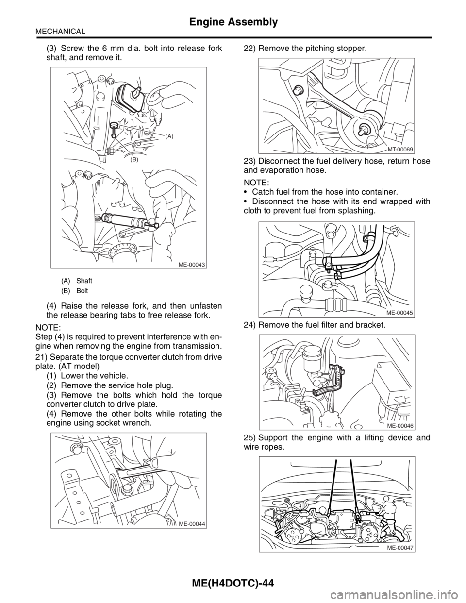
(3) Screw the 6 mm dia. bolt into release fork
shaft, and remove it.
(4) Raise the release fork, and then unfasten
the release bearing tabs to free release fork.
NOTE:
Step (4) is required to prevent interference with en-
gine when removing the engine from transmission.
21) Separate the torque converter clutch from drive
plate. (AT model)
(1) Lower the vehicle.
(2) Remove the service hole plug.
(3) Remove the bolts which hold the torque
converter clutch to drive plate.
(4) Remove the other bolts while rotating the
engine using socket wrench.22) Remove the pitching stopper.
23) Disconnect the fuel delivery hose, return hose
and evaporation hose.
NOTE:
Catch fuel from the hose into container.
Disconnect the hose with its end wrapped with
cloth to prevent fuel from splashing.
24) Remove the fuel filter and bracket.
25) Support the engine with a lifting device and
wire ropes.
(A) Shaft
(B) Bolt
ME-00043 (B)(A)
ME-00044
MT-00069
ME-00045
ME-00046
ME-00047