2004 SUBARU FORESTER transmission
[x] Cancel search: transmissionPage 2202 of 2870

EN(H4DOTC 2.5)-178
ENGINE (DIAGNOSTIC)
Diagnostic Procedure with Diagnostic Trouble Code (DTC)
AW:DTC P0700 TRANSMISSION CONTROL SYSTEM (MIL REQUEST)
NOTE:
For the diagnostic procedure, refer to AT section.
Step Check Yes No
1 CHECK OUTPUT SIGNAL FROM ECM.
1) Turn the ignition switch to OFF.
2) Connect the test mode connector.
3) Turn the ignition switch to ON.
4) While operating the radiator fan relay, mea-
sure voltage between ECM and chassis ground.
N
OTE:
Radiator fan relay operation can be executed
using Subaru Select Monitor. For procedure,
refer to “Compulsory Valve Operation Check
Mode”.
Connector & terminal
(B135) No. 24 (+) — Chassis ground (
−):
(B135) No. 25 (+) — Chassis ground (
−):Does the voltage vary between
0 — 10 V?Even if the mal-
function indicator
light illuminates,
the circuit has
returned to a nor-
mal condition at
this time. In this
case, repair poor
contact in ECM
connector.Go to step 2.
2 CHECK SHORT CIRCUIT IN RADIATOR FAN
RELAY CONTROL CIRCUIT.
1) Turn the ignition switch to OFF.
2) Remove the main fan relay, sub fan relay
and fan mode relay.
3) Disconnect the test mode connectors
4) Turn the ignition switch to ON.
5) Measure the voltage between ECM and
chassis ground.
Connector & terminal
(B135) No. 24 (+) — Chassis ground (
−):
(B135) No. 25 (+) — Chassis ground (
−):Is the voltage more than 10 V? Repair battery
short circuit in radi-
ator fan relay con-
trol circuit. After
repair, replace the
ECM.
41, Engine Con-
trol Module
(ECM).>Go to step 3.
3 CHECK FAN RELAY.
1) Turn the ignition switch to OFF.
2) Remove the fan relay.
3) Measure the resistance between fan relay
terminals.
Te r m i n a l s
No. 30 — No. 31 (Main fan relay)
No. 28 — No. 29 (Sub fan relay)Is the resistance less than 1
Ω?Replace the fan
relay and ECM.
41, Engine Con-
trol Module
(ECM).>Go to step 4.
4 CHECK FAN MODE RELAY.
1) Remove the fan mode relay.
2) Measure the resistance between fan mode
relay terminals.
Te r m i n a l s
No. 8 — No. 9: (Fan mode relay)Is the resistance less than 1
Ω?Replace the fan
mode relay and
ECM.
41, Engine Con-
trol Module
(ECM).>Go to step 5.
5 CHECK POOR CONTACT.
Check poor contact in ECM connector.Is there poor contact in ECM
connector?Repair the poor
contact in ECM
connector.Replace the ECM.
41, Engine Con-
trol Module
(ECM).>
Page 2204 of 2870

EN(H4DOTC 2.5)-180
ENGINE (DIAGNOSTIC)
Diagnostic Procedure with Diagnostic Trouble Code (DTC)
Step Check Yes No
1 CHECK INPUT SIGNAL FROM ECM.
1) Turn the ignition switch to ON.
2) Shift the select lever to other than “N” and
“P” ranges.
3) Measure the voltage between ECM and
chassis ground.
Connector & terminal
(B137) No. 9 (+) — Chassis ground (
−):Is the voltage 4.5 — 5.5 V? Even if the mal-
function indicator
light illuminates,
the circuit has
returned to a nor-
mal condition at
this time.Go to step 2.
2 CHECK HARNESS BETWEEN ECM AND
TRANSMISSION HARNESS CONNECTOR.
1) Turn the ignition switch to OFF.
2) Disconnect the connectors from ECM and
transmission harness connector (T3).
3) Measure the resistance of harness
between ECM connector and chassis ground.
Connector & terminal
(B137) No. 9 — Chassis ground:Is the resistance more than 1
MΩ?Go to step 3.Repair ground
short circuit in har-
ness between
ECM and trans-
mission harness
connector.
3 CHECK TRANSMISSION HARNESS CON-
NECTOR.
1) Disconnect the connector from inhibitor switch.
2) Measure the resistance of harness
between transmission harness connector and
engine ground.
Connector & terminal
(T3) No. 12 — Engine ground:Is the resistance more than 1
MΩ?Go to step 4.Repair ground
short circuit in har-
ness between
transmission har-
ness and inhibitor
switch connector.
4 CHECK INHIBITOR SWITCH.
Measure the resistance between inhibitor
switch connector the receptacle’s terminals in
selector lever except for “N” range.
Te r m i n a l s
No. 7 — No. 12:Is the resistance more than 1
MΩ?Go to step 5.Replace the inhibi-
tor switch.
Switch.>
5 CHECK SELECTOR CABLE CONNECTION.Is there any fault in selector cable
connection to inhibitor switch?Repair selector
cable connection.
Select Cable.>Contact the SUB-
ARU dealer.
N
OTE:
Inspection by DTM
is required, be-
cause probable
cause is deteriora-
tion of multiple
parts.
Page 2206 of 2870

EN(H4DOTC 2.5)-182
ENGINE (DIAGNOSTIC)
Diagnostic Procedure with Diagnostic Trouble Code (DTC)
Step Check Yes No
1 CHECK INPUT SIGNAL FROM ECM.
1) Turn the ignition switch to ON.
2) Place the shift lever in neutral.
3) Measure the voltage between ECM and
chassis ground.
Connector & terminal
(B137) No. 9 (+) — Chassis ground (
−):Is the voltage more than 10 V? Go to step 2.Go to step 4.
2 CHECK INPUT SIGNAL FROM ECM.
1) Place the shift lever except in neutral.
2) Measure the voltage between ECM and
chassis ground.
Connector & terminal
(B137) No. 9 (+) — Chassis ground (
−):Is the voltage less than 1 V? Go to step 3.Go to step 4.
3 CHECK POOR CONTACT.
Check poor contact in ECM connector.Is there poor contact in ECM
connector?Repair the poor
contact in ECM
connector.Contact the SUB-
ARU dealer.
4 CHECK NEUTRAL POSITION SWITCH.
1) Turn the ignition switch to OFF.
2) Disconnect the connector from transmis-
sion harness.
3) Place the shift lever in neutral.
4) Measure the resistance between transmis-
sion harness and connector terminals.
Connector & terminal
(T9) No. 1 — No. 3:Is the resistance more than 1
MΩ?Go to step 5.Repair short circuit
in transmission
harness or replace
the neutral position
switch.
5 CHECK NEUTRAL POSITION SWITCH.
1) Place the shift lever except in neutral.
2) Measure the resistance between transmis-
sion harness connector terminals.
Te r m i n a l s
No. 1 — No. 3:Is the resistance less than 1
Ω?Go to step 6.Repair short circuit
in transmission
harness or replace
the neutral position
switch.
6 CHECK HARNESS BETWEEN ECM AND
NEUTRAL POSITION SWITCH CONNEC-
TOR.
Measure the resistance between ECM and
chassis ground.
Connector & terminal
(B137) No. 9 — Chassis ground:Is the resistance more than 1
MΩ?Go to step 7.Repair ground
short circuit in har-
ness between
ECM and trans-
mission harness
connector.
7 CHECK HARNESS BETWEEN ECM AND
NEUTRAL POSITION SWITCH CONNEC-
TOR.
1) Disconnect the connector from ECM.
2) Measure the resistance of harness between
ECM and transmission harness connector.
Connector & terminal
(B137) No. 9 — (B128) No. 1:Is the resistance less than 1
Ω?Go to step 8.Repair open circuit
in harness
between ECM and
transmission har-
ness connector.
8 CHECK HARNESS BETWEEN ECM AND
NEUTRAL POSITION SWITCH CONNEC-
TOR.
Measure the resistance of harness between
transmission harness connector and engine
ground.
Connector & terminal
(B128) No. 1 — Engine ground:Is the resistance less than 5
Ω?Go to step 9.Repair open circuit
between transmis-
sion harness con-
nector and engine
ground terminal.
9 CHECK POOR CONTACT.
Check poor contact in transmission harness
connector.Is there poor contact in trans-
mission harness connector?Repair poor con-
tact in transmission
harness connector.Contact the SUB-
ARU dealer.
Page 2211 of 2870

EN(H4DOTC 2.5)-187
ENGINE (DIAGNOSTIC)
Diagnostic Procedure with Diagnostic Trouble Code (DTC)
Step Check Yes No
1 CHECK INPUT SIGNAL FROM ECM.
1) Turn the ignition switch to ON.
2) Place the shift lever except in neutral posi-
tion.
3) Measure the voltage between ECM and
chassis ground.
Connector & terminal
(B137) No. 9 (+) — Chassis ground (
−):Is the voltage less than 1 V? Go to step 2.Go to step 4.
2 CHECK INPUT SIGNAL FROM ECM.
1) Place the shift lever in neutral position.
2) Measure the voltage between ECM and
chassis ground.
Connector & terminal
(B137) No. 9 (+) — Chassis ground (
−):Is the voltage more than 10 V? Go to step 3.Go to step 4.
3 CHECK POOR CONTACT.
Check poor contact in ECM connector.Is there poor contact in ECM
connector?Repair the poor
contact in ECM
connector.Contact the SUB-
ARU dealer.
4 CHECK INPUT SIGNAL FROM ECM.
1) Disconnect the connector from ECM.
2) Measure the voltage between ECM and
chassis ground.
Connector & terminal
(B137) No. 9 (+) — Chassis ground (
−):Is the voltage more than 10 V? Repair battery
short circuit in har-
ness between
ECM and trans-
mission harness
connector.Go to step 5.
5 CHECK HARNESS BETWEEN ECM AND
TRANSMISSION HARNESS CONNECTOR.
1) Turn the ignition switch to OFF.
2) Disconnect the connectors from ECM and
transmission harness connector (T9).
3) Measure the resistance of harness
between ECM and neutral switch connector.
Connector & terminal
(B137) No. 9 — (B128) No. 1:Is the resistance less than 1
Ω?Go to step 6.Repair the harness
and connector.
N
OTE:
In this case repair
the following:
Open circuit in
harness between
ECM and trans-
mission harness
connector
Poor contact in
transmission har-
ness connector.
Poor contact in
ECM connector.
6 CHECK NEUTRAL POSITION SWITCH
GROUND LINE.
Measure the resistance of harness between
transmission harness connector and engine
ground.
Connector & terminal
(B128) No. 3 — Engine ground:Is the resistance less than 5
Ω?Go to step 7.Repair open circuit
in the neutral posi-
tion switch ground
line.
7 CHECK NEUTRAL POSITION SWITCH.
1) Place the shift lever except in neutral posi-
tion.
2) Measure the resistance between transmis-
sion harness connector socket terminals.
Te r m i n a l s
No. 1 — No. 3:Is the resistance less than 1
Ω?Go to step 8.Replace the neu-
tral position switch.
8 CHECK POOR CONTACT.
Check poor contact in transmission harness
connector.Is there poor contact in trans-
mission harness connector?Repair poor contact
in transmission har-
ness connector.Contact the SUB-
ARU dealer.
Page 2285 of 2870

FUJI HEAVY INDUSTRIES LTD. G8080GE5
2004 FORESTER SERVICE MANUAL QUICK REFERENCE INDEX
TRANSMISSION SECTION
This service manual has been prepared
to provide SUBARU service personnel
with the necessary information and data
for the correct maintenance and repair
of SUBARU vehicles.
This manual includes the procedures
for maintenance, disassembling, reas-
sembling, inspection and adjustment of
components and diagnostics for guid-
ance of experienced mechanics.
Please peruse and utilize this manual
fully to ensure complete repair work for
satisfying our customers by keeping
their vehicle in optimum condition.
When replacement of parts during
repair work is needed, be sure to use
SUBARU genuine parts.
All information, illustration and specifi-
cations contained in this manual are
based on the latest product information
available at the time of publication
approval.CONTROL SYSTEM CS
AUTOMATIC TRANSMISSION 4AT
AUTOMATIC TRANSMISSION
(DIAGNOSTIC)4AT(H4SO)
AUTOMATIC TRANSMISSION
(DIAGNOSTIC)4AT(H4DOTC)
AUTOMATIC TRANSMISSION
(DIAGNOSTIC)4AT(H4DOTC 2.5)
MANUAL TRANSMISSION AND
DIFFERENTIAL5MT
CLUTCH SYSTEM CL
Page 2298 of 2870

CS-13
CONTROL SYSTEM
Select Cable
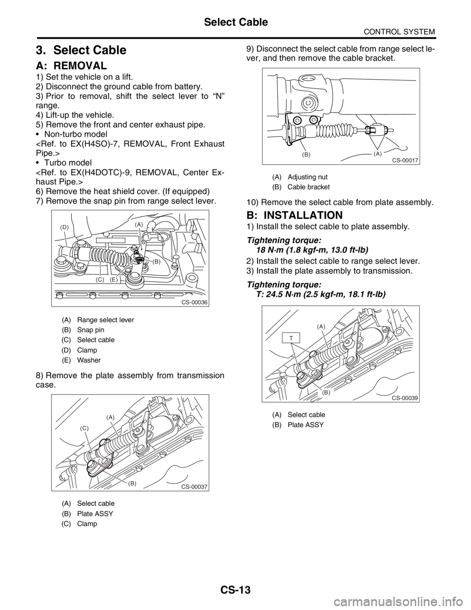
3. Select Cable
A: REMOVAL
1) Set the vehicle on a lift.
2) Disconnect the ground cable from battery.
3) Prior to removal, shift the select lever to “N”
range.
4) Lift-up the vehicle.
5) Remove the front and center exhaust pipe.
Non-turbo model
Turbo model
6) Remove the heat shield cover. (If equipped)
7) Remove the snap pin from range select lever.
8) Remove the plate assembly from transmission
case.9) Disconnect the select cable from range select le-
ver, and then remove the cable bracket.
10) Remove the select cable from plate assembly.
B: INSTALLATION
1) Install the select cable to plate assembly.
Tightening torque:
18 N·m (1.8 kgf-m, 13.0 ft-lb)
2) Install the select cable to range select lever.
3) Install the plate assembly to transmission.
Tightening torque:
T: 24.5 N·m (2.5 kgf-m, 18.1 ft-lb)
(A) Range select lever
(B) Snap pin
(C) Select cable
(D) Clamp
(E) Washer
(A) Select cable
(B) Plate ASSY
(C) Clamp
CS-00036
(C)(B) (A)
(E) (D)
CS-00037
(A)
(C)
(B)
(A) Adjusting nut
(B) Cable bracket
(A) Select cable
(B) Plate ASSY
CS-00017(B)(A)
CS-00039
(A)
(B)
T
Page 2302 of 2870

CS-17
CONTROL SYSTEM
MT Gear Shift Lever
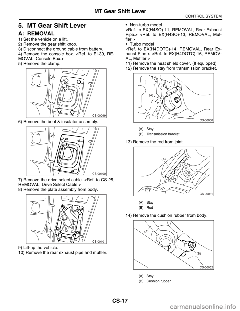
5. MT Gear Shift Lever
A: REMOVAL
1) Set the vehicle on a lift.
2) Remove the gear shift knob.
3) Disconnect the ground cable from battery.
4) Remove the console box.
5) Remove the clamp.
6) Remove the boot & insulator assembly.
7) Remove the drive select cable.
8) Remove the plate assembly from body.
9) Lift-up the vehicle.
10) Remove the rear exhaust pipe and muffler. Non-turbo model
Turbo model
11) Remove the heat shield cover. (If equipped)
12) Remove the stay from transmission bracket.
13) Remove the rod from joint.
14) Remove the cushion rubber from body.
CS-00099
CS-00100
CS-00101
(A) Stay
(B) Transmission bracket
(A) Stay
(B) Rod
(A) Stay
(B) Cushion rubber
CS-00050
(A)
(B)
CS-00051
(A)
(B)
CS-00052
(A)
(B)
Page 2303 of 2870

CS-18
CONTROL SYSTEM
MT Gear Shift Lever
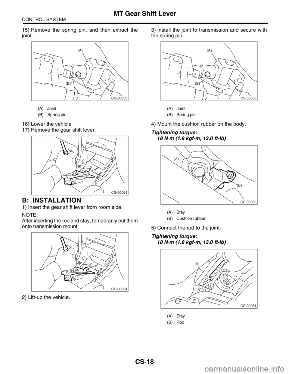
15) Remove the spring pin, and then extract the
joint.
16) Lower the vehicle.
17) Remove the gear shift lever.
B: INSTALLATION
1) Insert the gear shift lever from room side.
NOTE:
After inserting the rod and stay, temporarily put them
onto transmission mount.
2) Lift-up the vehicle.3) Install the joint to transmission and secure with
the spring pin.
4) Mount the cushion rubber on the body.
Tightening torque:
18 N·m (1.8 kgf-m, 13.0 ft-lb)
5) Connect the rod to the joint.
Tightening torque:
18 N·m (1.8 kgf-m, 13.0 ft-lb)
(A) Joint
(B) Spring pin
CS-00053
(A)
(B)
CS-00054
CS-00054
(A) Joint
(B) Spring pin
(A) Stay
(B) Cushion rubber
(A) Stay
(B) Rod
CS-00053
(A)
(B)
CS-00052
(A)
(B)
CS-00051
(A)
(B)