Page 1928 of 2870

EN(H4DOTC)-295
ENGINE (DIAGNOSTIC)
General Diagnostic Table
20.General Diagnostic Table
A: INSPECTION
1. ENGINE
NOTE:
Malfunction of parts other than those listed is also possible.
General.>
Symptom Problem parts
1. Engine stalls during idling.1) Idle air control solenoid valve
2) Manifold absolute pressure sensor
3) Mass air flow and intake air temperature sensor
4) Ignition parts (*1)
5) Engine coolant temperature sensor (*2)
6) Crankshaft position sensor (*3)
7) Camshaft position sensor (*3)
8) Fuel injection parts (*4)
2. Rough idling1) Idle air control solenoid valve
2) Manifold absolute pressure sensor
3) Mass air flow and intake air temperature sensor
4) Engine coolant temperature sensor (*2)
5) Ignition parts (*1)
6) Air intake system (*5)
7) Fuel injection parts (*4)
8) Throttle position sensor
9) Crankshaft position sensor (*3)
10) Camshaft position sensor (*3)
11) Oxygen sensor
12) Fuel pump and fuel pump relay
3. Engine does not return to idle.1) Idle air control solenoid valve
2) Engine coolant temperature sensor
3) Accelerator cable (*6)
4) Throttle position sensor
5) Manifold absolute pressure sensor
6) Mass air flow sensor
4. Poor acceleration1) Manifold absolute pressure sensor
2) Mass air flow and intake air temperature sensor
3) Throttle position sensor
4) Fuel injection parts (*4)
5) Fuel pump and fuel pump relay
6) Engine coolant temperature sensor (*2)
7) Crankshaft position sensor (*3)
8) Camshaft position sensor (*3)
9) A/C switch and A/C cut relay
10) Engine torque control signal circuit
11) Ignition parts (*1)
5. Engine stalls or engine sags or hesitates at
acceleration.1) Manifold absolute pressure sensor
2) Mass air flow and intake air temperature sensor
3) Engine coolant temperature sensor (*2)
4) Crankshaft position sensor (*3)
5) Camshaft position sensor (*3)
6) Purge control solenoid valve
7) Fuel injection parts (*4)
8) Throttle position sensor
9) Fuel pump and fuel pump relay
Page 1929 of 2870

EN(H4DOTC)-296
ENGINE (DIAGNOSTIC)
General Diagnostic Table
*1: Check ignition coil & ignitor ASSY and spark plug.
*2: Indicate the symptom occurring only in cold temperatures.
*3: Ensure the secure installation.
*4: Check fuel injector, fuel pressure regulator and fuel filter.
*5: Inspect air leak in air intake system.
*6: Adjust accelerator cable. 6. Surging1) Manifold absolute pressure sensor
2) Mass air flow and intake air temperature sensor
3) Engine coolant temperature sensor (*2)
4) Crankshaft position sensor (*3)
5) Camshaft position sensor (*3)
6) Fuel injection parts (*4)
7) Throttle position sensor
8) Fuel pump and fuel pump relay
7. Spark knock1) Manifold absolute pressure sensor
2) Mass air flow and intake air temperature sensor
3) Engine coolant temperature sensor
4) Knock sensor
5) Fuel injection parts (*4)
6) Fuel pump and fuel pump relay
8. After burning in exhaust system1) Manifold absolute pressure sensor
2) Mass air flow and intake air temperature sensor
3) Engine coolant temperature sensor (*2)
4) Fuel injection parts (*4)
5) Fuel pump and fuel pump relay Symptom Problem parts
Page 1930 of 2870

FUJI HEAVY INDUSTRIES LTD. G8080GE4
2004 FORESTER SERVICE MANUAL QUICK REFERENCE INDEX
ENGINE SECTION 3
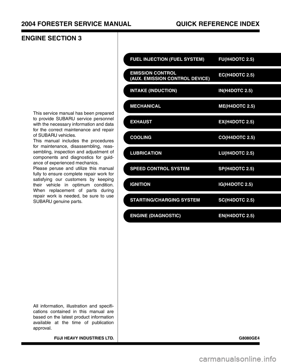
This service manual has been prepared
to provide SUBARU service personnel
with the necessary information and data
for the correct maintenance and repair
of SUBARU vehicles.
This manual includes the procedures
for maintenance, disassembling, reas-
sembling, inspection and adjustment of
components and diagnostics for guid-
ance of experienced mechanics.
Please peruse and utilize this manual
fully to ensure complete repair work for
satisfying our customers by keeping
their vehicle in optimum condition.
When replacement of parts during
repair work is needed, be sure to use
SUBARU genuine parts.
All information, illustration and specifi-
cations contained in this manual are
based on the latest product information
available at the time of publication
approval.FUEL INJECTION (FUEL SYSTEM) FU(H4DOTC 2.5)
EMISSION CONTROL
(AUX. EMISSION CONTROL DEVICE)EC(H4DOTC 2.5)
INTAKE (INDUCTION) IN(H4DOTC 2.5)
MECHANICAL ME(H4DOTC 2.5)
EXHAUST EX(H4DOTC 2.5)
COOLING CO(H4DOTC 2.5)
LUBRICATION LU(H4DOTC 2.5)
SPEED CONTROL SYSTEM SP(H4DOTC 2.5)
IGNITION IG(H4DOTC 2.5)
STARTING/CHARGING SYSTEM SC(H4DOTC 2.5)
ENGINE (DIAGNOSTIC) EN(H4DOTC 2.5)
Page 1946 of 2870
FU(H4DOTC 2.5)-16
FUEL INJECTION (FUEL SYSTEM)
Intake Manifold
18) Disconnect the knock sensor connector.
19) Disconnect the connector from the camshaft
position sensor.
20) Disconnect the connector from the ignition coil.
RH SIDE
LH SIDE
21) Disconnect the engine harness fixed by clip (A)
from the bracket. RH SIDE
LH SIDE
22) Disconnect the fuel delivery hose, return hose
and evaporation hose.
CAUTION:
Do not spill fuel.
Catch fuel from hoses in a container or cloth.
23) Remove the bolts which secure the intake man-
ifold to the cylinder heads.
24) Remove the intake manifold.
FU-00028
FU-01038
FU-01307
FU-01308
FU-01309 (A)
FU-01310
(A)
FU-00032
FU-01039
Page 1947 of 2870
FU(H4DOTC 2.5)-17
FUEL INJECTION (FUEL SYSTEM)
Intake Manifold
B: INSTALLATION
1) Install the intake manifold onto cylinder heads.
NOTE:
Always use new gaskets.
Tightening torque:
25 N·m (2.5 kgf-m, 18.1 ft-lb)
2) Connect the fuel delivery hose, return hose and
evaporation hose.
3) Connect the connector to the oil pressure switch
(B), crankshaft position sensor (C) and engine cool-
ant temperature sensor (A).4) Connect the connector to the knock sensor.
5) Connect the connector to the camshaft position
sensor.
6) Connect the connector to the ignition coil.
7) Connect the engine harness with clip (A) to the
bracket.
RH SIDE
FU-01039
FU-00032
(A)
(B)
(C)
FU-00027
FU-00028
FU-01038
FU-00030
FU-01309 (A)
Page 1975 of 2870
FU(H4DOTC 2.5)-45
FUEL INJECTION (FUEL SYSTEM)
Fuel
21.Fuel
A: OPERATION
1. RELEASING OF FUEL PRESSURE
WARNING:
Place “NO FIRE” signs near the working area.
Be careful not to spill fuel on the floor.
1) Disconnect the connector from fuel pump relay.
2) Start the engine and run it until it stalls.
3) After the engine stalls, crank it for 5 more seconds.
4) Turn the ignition switch to OFF.
2. DRAINING FUEL
WARNING:
Place “NO FIRE” signs near the working area.
Be careful not to spill fuel on the floor.
1) Set the vehicle on a lift.
2) Disconnect the ground cable from battery.
3) Open the fuel filler flap lid and remove fuel filler
cap.
4) Lift-up the vehicle.5) Drain fuel from the fuel tank.
Set a container under the vehicle and remove the
drain plug from fuel tank.
6) Tighten the fuel drain plug.
Tightening torque:
26 N·m (2.7 kgf-m, 19.2 ft-lb)
FU-00262
FU-00009
FU-00089
FU-00089
Page 1995 of 2870

FUJI HEAVY INDUSTRIES LTD. G8080GE4
2004 FORESTER SERVICE MANUAL QUICK REFERENCE INDEX
ENGINE SECTION 3
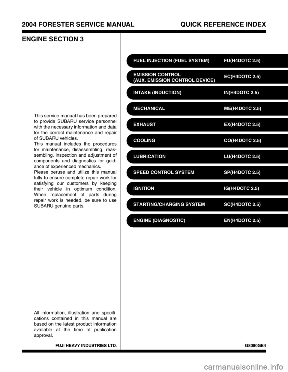
This service manual has been prepared
to provide SUBARU service personnel
with the necessary information and data
for the correct maintenance and repair
of SUBARU vehicles.
This manual includes the procedures
for maintenance, disassembling, reas-
sembling, inspection and adjustment of
components and diagnostics for guid-
ance of experienced mechanics.
Please peruse and utilize this manual
fully to ensure complete repair work for
satisfying our customers by keeping
their vehicle in optimum condition.
When replacement of parts during
repair work is needed, be sure to use
SUBARU genuine parts.
All information, illustration and specifi-
cations contained in this manual are
based on the latest product information
available at the time of publication
approval.FUEL INJECTION (FUEL SYSTEM) FU(H4DOTC 2.5)
EMISSION CONTROL
(AUX. EMISSION CONTROL DEVICE)EC(H4DOTC 2.5)
INTAKE (INDUCTION) IN(H4DOTC 2.5)
MECHANICAL ME(H4DOTC 2.5)
EXHAUST EX(H4DOTC 2.5)
COOLING CO(H4DOTC 2.5)
LUBRICATION LU(H4DOTC 2.5)
SPEED CONTROL SYSTEM SP(H4DOTC 2.5)
IGNITION IG(H4DOTC 2.5)
STARTING/CHARGING SYSTEM SC(H4DOTC 2.5)
ENGINE (DIAGNOSTIC) EN(H4DOTC 2.5)
Page 1998 of 2870

FUJI HEAVY INDUSTRIES LTD. G8080GE4
2004 FORESTER SERVICE MANUAL QUICK REFERENCE INDEX
ENGINE SECTION 3
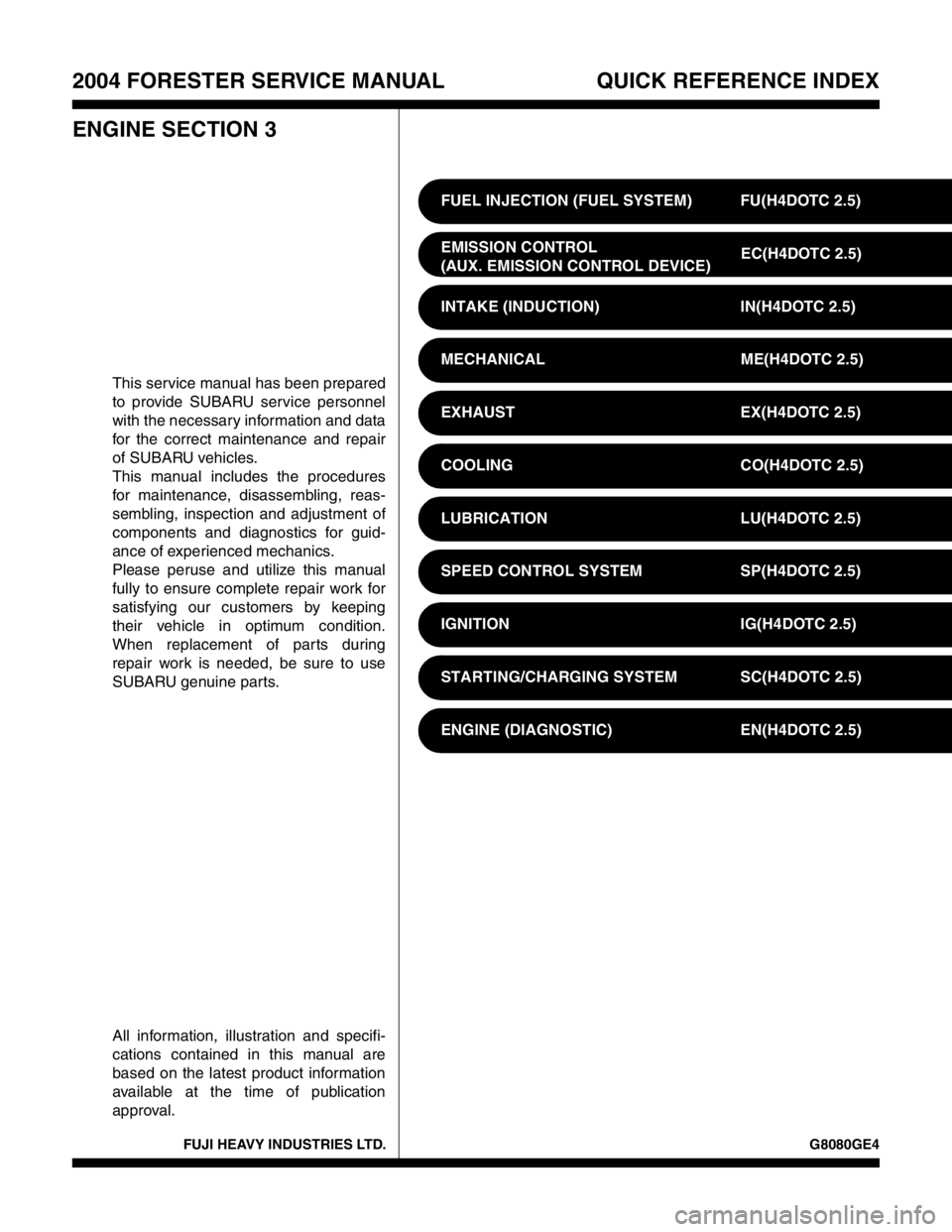
This service manual has been prepared
to provide SUBARU service personnel
with the necessary information and data
for the correct maintenance and repair
of SUBARU vehicles.
This manual includes the procedures
for maintenance, disassembling, reas-
sembling, inspection and adjustment of
components and diagnostics for guid-
ance of experienced mechanics.
Please peruse and utilize this manual
fully to ensure complete repair work for
satisfying our customers by keeping
their vehicle in optimum condition.
When replacement of parts during
repair work is needed, be sure to use
SUBARU genuine parts.
All information, illustration and specifi-
cations contained in this manual are
based on the latest product information
available at the time of publication
approval.FUEL INJECTION (FUEL SYSTEM) FU(H4DOTC 2.5)
EMISSION CONTROL
(AUX. EMISSION CONTROL DEVICE)EC(H4DOTC 2.5)
INTAKE (INDUCTION) IN(H4DOTC 2.5)
MECHANICAL ME(H4DOTC 2.5)
EXHAUST EX(H4DOTC 2.5)
COOLING CO(H4DOTC 2.5)
LUBRICATION LU(H4DOTC 2.5)
SPEED CONTROL SYSTEM SP(H4DOTC 2.5)
IGNITION IG(H4DOTC 2.5)
STARTING/CHARGING SYSTEM SC(H4DOTC 2.5)
ENGINE (DIAGNOSTIC) EN(H4DOTC 2.5)