Page 1964 of 2870
FU(H4DOTC 2.5)-34
FUEL INJECTION (FUEL SYSTEM)
Tumble Generator Valve Actuator
12.Tumble Generator Valve Ac-
tuator
A: REMOVAL
1. RH SIDE
1) Release the fuel pressure.
FUEL PRESSURE, OPERATION, Fuel.>
2) Open the fuel filler flap lid and remove the fuel
filler cap.
3) Disconnect the ground cable from battery.
4) Remove the intake manifold.
Manifold.>
5) Disconnect the connector from tumble generator
valve actuator RH.
6) Remove the tumble generator valve actuator RH.
2. LH SIDE
1) Release the fuel pressure.
FUEL PRESSURE, OPERATION, Fuel.>
2) Open the fuel filler flap lid and remove the fuel
filler cap.
3) Disconnect the ground cable from battery.
4) Disconnect the connector from tumble generator
valve actuator LH.
5) Remove the tumble generator valve actuator LH.
B: INSTALLATION
1. RH SIDE
Install in the reverse order of removal.
2. LH SIDE
Install in the reverse order of removal.
FU-00009
FU-00621
FU-00009
FU-00622
Page 1965 of 2870
FU(H4DOTC 2.5)-35
FUEL INJECTION (FUEL SYSTEM)
Wastegate Control Solenoid Valve
13.Wastegate Control Solenoid
Valve
A: REMOVAL
1) Disconnect the ground cable from battery.
2) Disconnect the engine harness connector (A)
from bracket.
3) Disconnect the connector (B) from wastegate
control solenoid valve.
4) Remove the bracket from body.
5) Disconnect the pressure hoses (C) from waste-
gate control solenoid valve.6) Remove the wastegate control solenoid valve
from bracket.
B: INSTALLATION
Install in the reverse order of removal.
Tightening torque:
6.5 N·m (0.66 kgf-m, 4.8 ft-lb)FU-00009
FU-00366
(A) (B)
FU-00367
(C)
FU-00368
FU-00368
Page 1966 of 2870
FU(H4DOTC 2.5)-36
FUEL INJECTION (FUEL SYSTEM)
Front Oxygen (A/F) Sensor
14.Front Oxygen (A/F) Sensor
A: REMOVAL
1) Disconnect the ground cable from battery.
2) Disconnect the connector from the front oxygen
(A/F) sensor.
3) Disconnect the engine harness fixed by clip (A)
from the bracket (B).
4) Remove the front right side wheel.
5) Lift-up the vehicle.
6) Remove the service hole cover.7) Apply SUBARU CRC or its equivalent to the
threaded portion of front oxygen (A/F) sensor, and
leave it for one minute or more.
SUBARU CRC (Part No. 004301003)
8) Remove the front oxygen (A/F) sensor.
CAUTION:
When removing the front oxygen (A/F) sensor,
wait until exhaust pipe cools; otherwise, it will
damage exhaust pipe.
FU-00009
FU-01229
FU-00078
(A)(B)
FU-00783
FU-00080
Page 1967 of 2870
FU(H4DOTC 2.5)-37
FUEL INJECTION (FUEL SYSTEM)
Front Oxygen (A/F) Sensor
B: INSTALLATION
1) Before installing front oxygen (A/F) sensor, ap-
ply anti-seize compound only to the threaded por-
tion of front oxygen (A/F) sensor to make the next
removal easier.
Anti-seize compound:
SS-30 JET LUBE
CAUTION:
Never apply anti-seize compound to protector
of front oxygen (A/F) sensor.
2) Install the front oxygen (A/F) sensor.
Tightening torque:
30 N·m (3.1 kgf-m, 22.1 ft-lb)
3) Install the service hole cover.
4) Lower the vehicle.
5) Install the front right side wheel.
6) Connect the engine harness to the bracket (B)
using clips (A).7) Connect the connector of front oxygen (A/F)
sensor.
8) Connect the battery ground cable to battery.
FU-00080
FU-00783
FU-00078
(A)(B)
FU-01229
FU-00009
Page 1968 of 2870

FU(H4DOTC 2.5)-38
FUEL INJECTION (FUEL SYSTEM)
Rear Oxygen Sensor
15.Rear Oxygen Sensor
A: REMOVAL
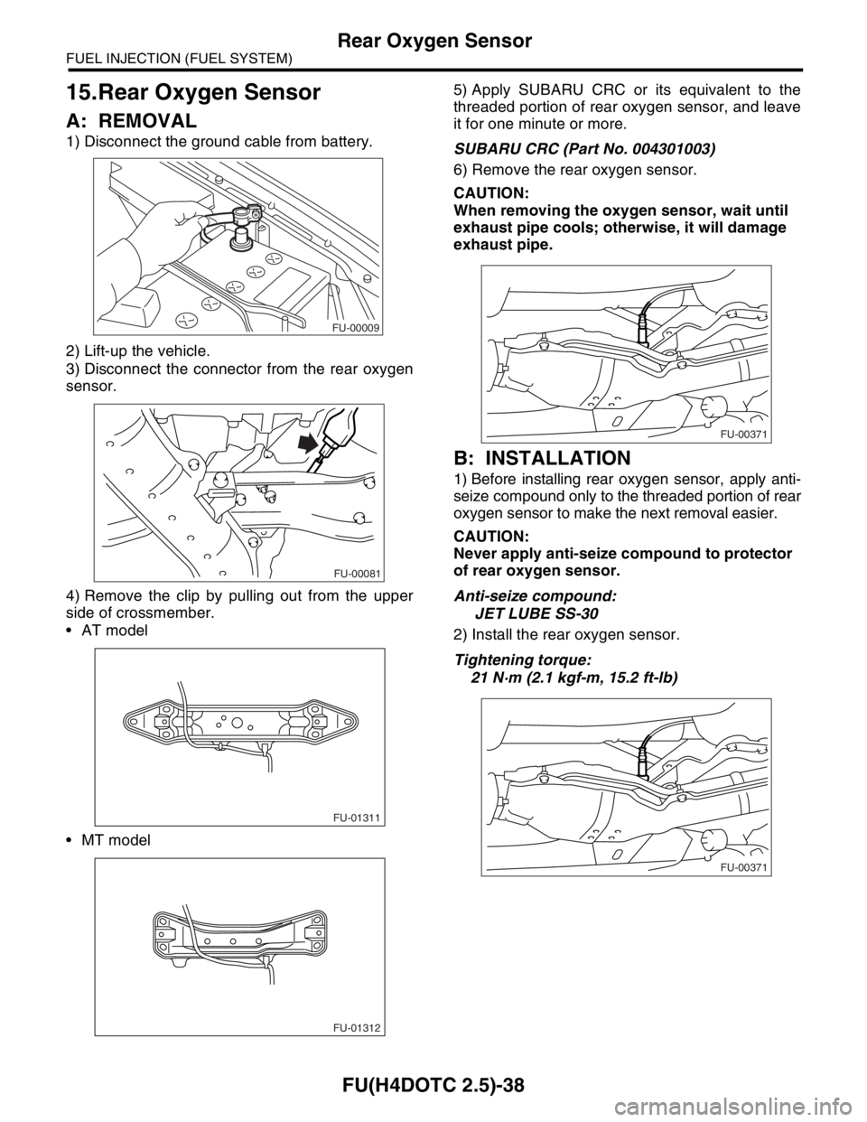
1) Disconnect the ground cable from battery.
2) Lift-up the vehicle.
3) Disconnect the connector from the rear oxygen
sensor.
4) Remove the clip by pulling out from the upper
side of crossmember.
AT model
MT model5) Apply SUBARU CRC or its equivalent to the
threaded portion of rear oxygen sensor, and leave
it for one minute or more.
SUBARU CRC (Part No. 004301003)
6) Remove the rear oxygen sensor.
CAUTION:
When removing the oxygen sensor, wait until
exhaust pipe cools; otherwise, it will damage
exhaust pipe.
B: INSTALLATION
1) Before installing rear oxygen sensor, apply anti-
seize compound only to the threaded portion of rear
oxygen sensor to make the next removal easier.
CAUTION:
Never apply anti-seize compound to protector
of rear oxygen sensor.
Anti-seize compound:
JET LUBE SS-30
2) Install the rear oxygen sensor.
Tightening torque:
21 N·m (2.1 kgf-m, 15.2 ft-lb)
FU-00009
FU-00081
FU-01311
FU-01312
FU-00371
FU-00371
Page 1969 of 2870
FU(H4DOTC 2.5)-39
FUEL INJECTION (FUEL SYSTEM)
Rear Oxygen Sensor
3) Connect the connector to the rear oxygen sensor.
4) Connect the clip to the crossmember.
AT model
MT model
5) Lower the vehicle.
6) Connect the battery ground cable to battery.
FU-00081
FU-01311
FU-01312
FU-00009
Page 1970 of 2870

FU(H4DOTC 2.5)-40
FUEL INJECTION (FUEL SYSTEM)
Exhaust Temperature Sensor
16.Exhaust Temperature Sensor
A: REMOVAL
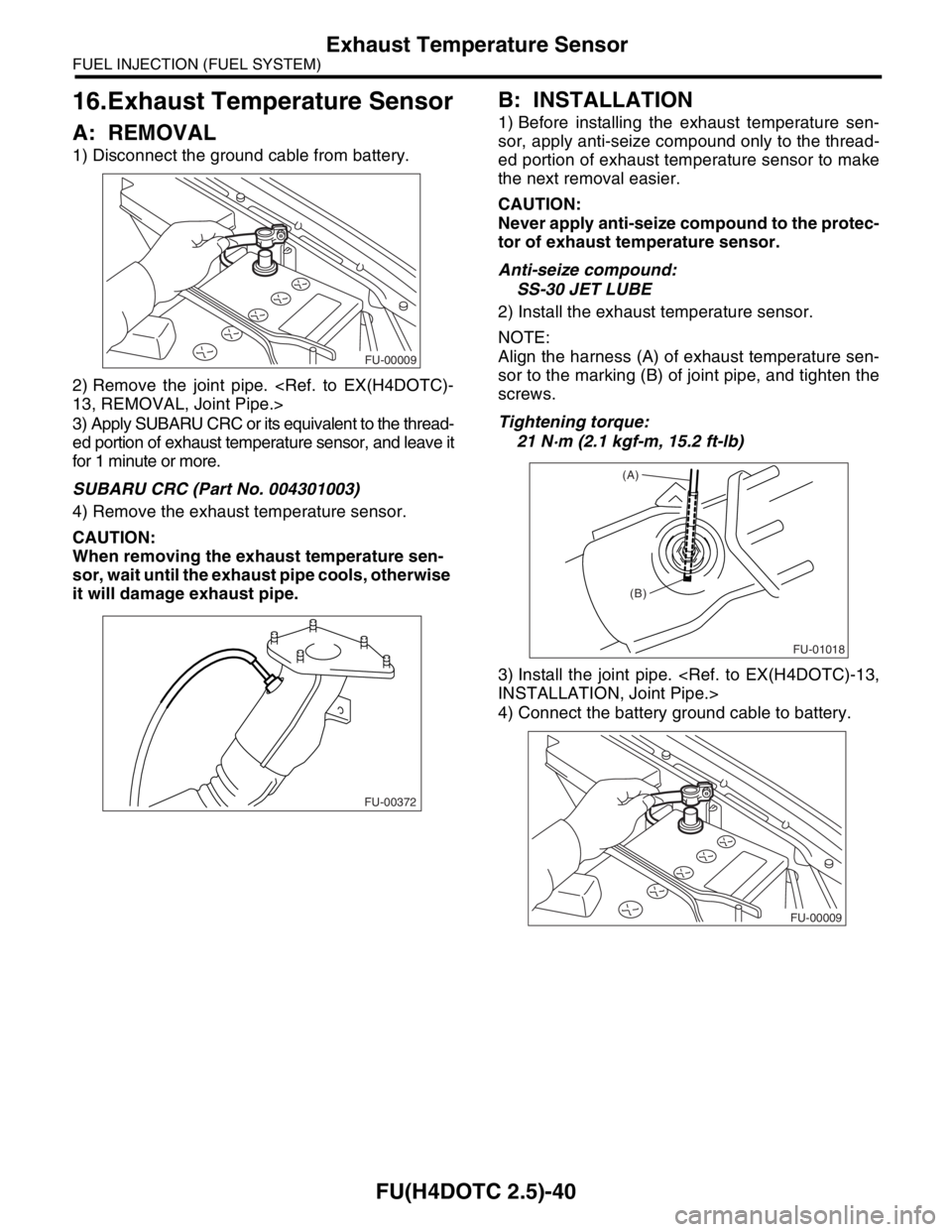
1) Disconnect the ground cable from battery.
2) Remove the joint pipe.
13, REMOVAL, Joint Pipe.>
3) Apply SUBARU CRC or its equivalent to the thread-
ed portion of exhaust temperature sensor, and leave it
for 1 minute or more.
SUBARU CRC (Part No. 004301003)
4) Remove the exhaust temperature sensor.
CAUTION:
When removing the exhaust temperature sen-
sor, wait until the exhaust pipe cools, otherwise
it will damage exhaust pipe.
B: INSTALLATION
1) Before installing the exhaust temperature sen-
sor, apply anti-seize compound only to the thread-
ed portion of exhaust temperature sensor to make
the next removal easier.
CAUTION:
Never apply anti-seize compound to the protec-
tor of exhaust temperature sensor.
Anti-seize compound:
SS-30 JET LUBE
2) Install the exhaust temperature sensor.
NOTE:
Align the harness (A) of exhaust temperature sen-
sor to the marking (B) of joint pipe, and tighten the
screws.
Tightening torque:
21 N·m (2.1 kgf-m, 15.2 ft-lb)
3) Install the joint pipe.
INSTALLATION, Joint Pipe.>
4) Connect the battery ground cable to battery.
FU-00009
FU-00372
FU-01018
(A)
(B)
FU-00009
Page 1971 of 2870
FU(H4DOTC 2.5)-41
FUEL INJECTION (FUEL SYSTEM)
Engine Control Module (ECM)
17.Engine Control Module (ECM)
A: REMOVAL
1) Disconnect the ground cable from battery.
2) Remove the lower inner trim of the passenger
side.
3) Detach the floor mat of the front passenger seat.
4) Remove the protect cover.
5) Remove the nuts (A) which hold ECM to the
bracket.
6) Remove the clip (B) from the bracket.
7) Disconnect the ECM connectors and take out
the ECM.
B: INSTALLATION
Install in the reverse order of removal.
NOTE:
When replacing ECM, be careful not to use the
wrong spec. ECM to avoid any damage to the fuel
injection system.
FU-00009
FU-01029
(A)
(A)
(B)
FU-00316