Page 1956 of 2870
FU(H4DOTC 2.5)-26
FUEL INJECTION (FUEL SYSTEM)
Engine Coolant Temperature Sensor
4. Engine Coolant Temperature
Sensor
A: REMOVAL
1) Disconnect the ground cable from battery.
2) Remove the generator.
REMOVAL, Generator.>
3) Drain the engine coolant.
DRAINING OF ENGINE COOLANT, REPLACE-
MENT, Engine Coolant.>
4) Disconnect the connector from the engine cool-
ant temperature sensor.
5) Remove the engine coolant temperature sensor.
B: INSTALLATION
Install in the reverse order of removal.
Tightening torque:
18 N·m (1.8 kgf-m, 13.3 ft-lb)
FU-00009
FU-00055
Page 1957 of 2870
FU(H4DOTC 2.5)-27
FUEL INJECTION (FUEL SYSTEM)
Crankshaft Position Sensor
5. Crankshaft Position Sensor
A: REMOVAL
1) Disconnect the ground cable from battery.
2) Remove the bolt which installs the crankshaft
position sensor to cylinder block.
3) Remove the crankshaft position sensor, and dis-
connect the connector from it.
B: INSTALLATION
Install in the reverse order of removal.
Tightening torque:
6.4 N·m (0.65 kgf-m, 4.7 ft-lb)
FU-00009
FU-00056
FU-00057
FU-00058
T
Page 1958 of 2870
FU(H4DOTC 2.5)-28
FUEL INJECTION (FUEL SYSTEM)
Camshaft Position Sensor
6. Camshaft Position Sensor
A: REMOVAL
1) Disconnect the ground cable from battery.
2) Disconnect the connector from the camshaft po-
sition sensor RH.
3) Remove the camshaft position sensor RH from
the backside of cylinder head.
4) Remove the camshaft position sensor LH same
as RH side.
B: INSTALLATION
Install in the reverse order of removal.
Tightening torque:
6.4 N·m (0.65 kgf-m, 4.7 ft-lb)
FU-00009
FU-01054
FU-01054
Page 1959 of 2870
FU(H4DOTC 2.5)-29
FUEL INJECTION (FUEL SYSTEM)
Knock Sensor
7. Knock Sensor
A: REMOVAL
1) Disconnect the ground cable from battery.
2) Remove the intercooler.
10, REMOVAL, Intercooler.>
3) Disconnect the knock sensor connector.
4) Remove the knock sensor from the cylinder
block.
B: INSTALLATION
1) Install the knock sensor to the cylinder block.
Tightening torque:
24 N·m (2.4 kgf-m, 17.4 ft-lb)
NOTE:
Extraction area of the knock sensor cord must be
positioned at a 60° angle relative to the engine rear.
2) Connect the knock sensor connector.
3) Install the intercooler.
INSTALLATION, Intercooler.>
4) Connect the battery ground cable to battery.
FU-00009
FU-00062
FU-00519
(A) Front side
FU-00413
(A)
60
FU-00062
FU-00009
Page 1960 of 2870
FU(H4DOTC 2.5)-30
FUEL INJECTION (FUEL SYSTEM)
Mass Air Flow and Intake Air Temperature Sensor
8. Mass Air Flow and Intake Air
Temperature Sensor
A: REMOVAL
1) Disconnect the ground cable from battery.
2) Disconnect the connector from mass air flow and
intake air temperature sensor.
3) Remove the mass air flow and intake air temper-
ature sensor.
B: INSTALLATION
Install in the reverse order of removal.
Tightening torque:
1.7 N·m (0.17 kgf-m, 1.3 ft-lb)
FU-00009
FU-00067
Page 1961 of 2870
FU(H4DOTC 2.5)-31
FUEL INJECTION (FUEL SYSTEM)
Manifold Absolute Pressure Sensor
9. Manifold Absolute Pressure
Sensor
A: REMOVAL
1) Disconnect the ground cable from battery.
2) Disconnect the connectors from manifold abso-
lute pressure sensor.
3) Remove the manifold absolute pressure sensor
from the throttle body.
B: INSTALLATION
Install in the reverse order of removal.
NOTE:
Replace the O-rings for the manifold absolute pres-
sure sensor with new ones.
Tightening torque:
1.6 N·m (0.16 kgf-m, 1.2 ft-lb)
FU-00009
FU-01077
Page 1962 of 2870

FU(H4DOTC 2.5)-32
FUEL INJECTION (FUEL SYSTEM)
Fuel Injector
10.Fuel Injector
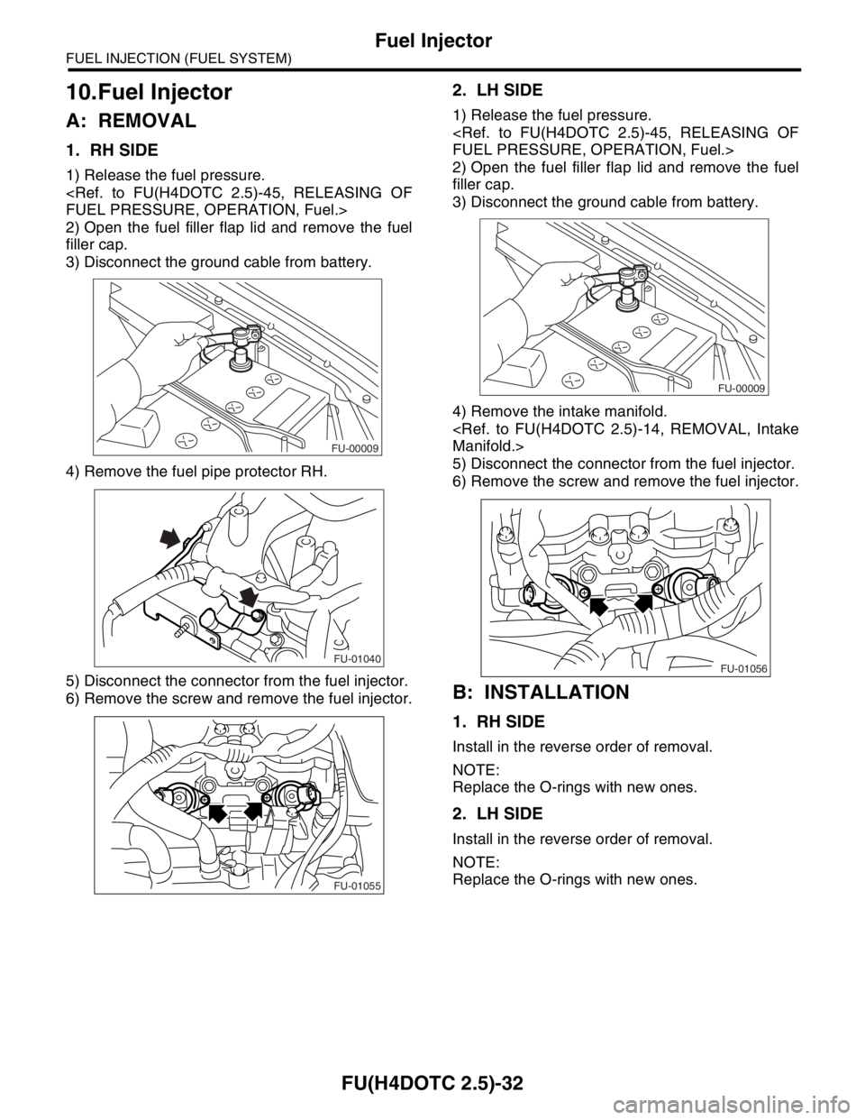
A: REMOVAL
1. RH SIDE
1) Release the fuel pressure.
FUEL PRESSURE, OPERATION, Fuel.>
2) Open the fuel filler flap lid and remove the fuel
filler cap.
3) Disconnect the ground cable from battery.
4) Remove the fuel pipe protector RH.
5) Disconnect the connector from the fuel injector.
6) Remove the screw and remove the fuel injector.
2. LH SIDE
1) Release the fuel pressure.
FUEL PRESSURE, OPERATION, Fuel.>
2) Open the fuel filler flap lid and remove the fuel
filler cap.
3) Disconnect the ground cable from battery.
4) Remove the intake manifold.
Manifold.>
5) Disconnect the connector from the fuel injector.
6) Remove the screw and remove the fuel injector.
B: INSTALLATION
1. RH SIDE
Install in the reverse order of removal.
NOTE:
Replace the O-rings with new ones.
2. LH SIDE
Install in the reverse order of removal.
NOTE:
Replace the O-rings with new ones.
FU-00009
FU-01040
FU-01055
FU-00009
FU-01056
Page 1963 of 2870
FU(H4DOTC 2.5)-33
FUEL INJECTION (FUEL SYSTEM)
Tumble Generator Valve Assembly
11.Tumble Generator Valve As-
sembly
A: REMOVAL
1) Release the fuel pressure.
FUEL PRESSURE, OPERATION, Fuel.>
2) Open the fuel filler flap lid and remove the fuel
filler cap.
3) Disconnect the ground cable from battery.
4) Remove the intake manifold.
Manifold.>
5) Disconnect the connector from the tumble gen-
erator valve sensor.
6) Disconnect the connector from the tumble gen-
erator valve actuator.
7) Remove the fuel injector.
jector.>8) Remove the tumble generator valve body from
the intake manifold.
B: INSTALLATION
Install in the reverse order of removal.
NOTE:
Always use new gaskets.
Tightening torque:
8.25 N·m (0.84 kgf-m, 6.1 ft-lb)
FU-00009
FU-00617
FU-00616
FU-00053
FU-00053