Page 1145 of 2870

EN(H4SO)-47
ENGINE (DIAGNOSTIC)
Malfunction Indicator Light
16.Malfunction Indicator Light
A: PROCEDURE
B: ACTIVATION OF MALFUNCTION
INDICATOR LIGHT
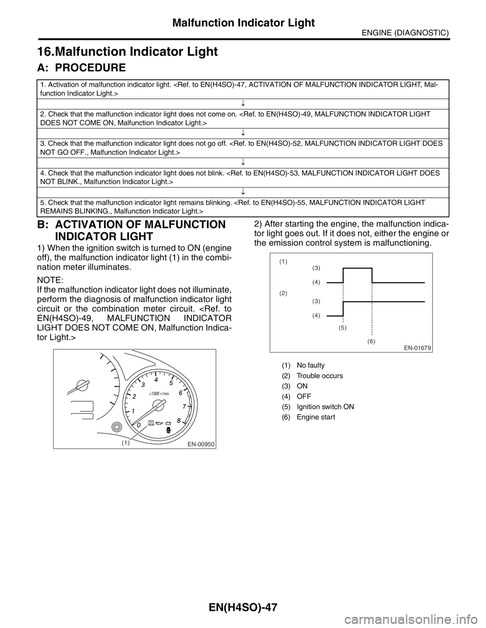
1) When the ignition switch is turned to ON (engine
off), the malfunction indicator light (1) in the combi-
nation meter illuminates.
NOTE:
If the malfunction indicator light does not illuminate,
perform the diagnosis of malfunction indicator light
circuit or the combination meter circuit.
EN(H4SO)-49, MALFUNCTION INDICATOR
LIGHT DOES NOT COME ON, Malfunction Indica-
tor Light.>2) After starting the engine, the malfunction indica-
tor light goes out. If it does not, either the engine or
the emission control system is malfunctioning.
1. Activation of malfunction indicator light.
function Indicator Light.>
↓
2. Check that the malfunction indicator light does not come on.
DOES NOT COME ON, Malfunction Indicator Light.>
↓
3. Check that the malfunction indicator light does not go off.
NOT GO OFF., Malfunction Indicator Light.>
↓
4. Check that the malfunction indicator light does not blink.
NOT BLINK., Malfunction Indicator Light.>
↓
5. Check that the malfunction indicator light remains blinking.
REMAINS BLINKING., Malfunction Indicator Light.>
EN-00950(1)
(1) No faulty
(2) Trouble occurs
(3) ON
(4) OFF
(5) Ignition switch ON
(6) Engine start
EN-01679
(1)
(2)
(5)
(6)(3)
(4)
(3)
(4)
Page 1146 of 2870
EN(H4SO)-48
ENGINE (DIAGNOSTIC)
Malfunction Indicator Light
3) If the diagnosis system detects a misfire which
could damage the catalyst, the malfunction indica-
tor light will blink at a cycle of 1 Hz.
4) When the ignition switch is turned to ON (engine
off) or to “START” with the test mode connector
connected, the malfunction indicator light blinks at
a cycle of 3 Hz.
(1) ON
(2) OFF
(3) Ignition switch ON
(4) Engine start
(5) Misfire start
(6) 1 second
(1) ON
(2) OFF
(3) Ignition switch ON
(4) 1 second
EN-01680
(2) (1)
(3)
(4)
(5)(6)
EN-01681
(2)(1)
(4)
(3)
Page 1147 of 2870
EN(H4SO)-49
ENGINE (DIAGNOSTIC)
Malfunction Indicator Light
C: MALFUNCTION INDICATOR LIGHT DOES NOT COME ON
DIAGNOSIS:
The malfunction indicator light circuit is open or shorted.
TROUBLE SYMPTOM:
When the ignition switch is turned ON (engine OFF), malfunction indicator light does not come on.
WIRING DIAGRAM:
EN-00259
i10
123456789101112131415161718192021222324252627282930
BATTERY
1
B72
B134IGNITION
SWITCH
i12 COMBINATION
METER
A:
i10 B:
SBF-44
28
ECM
B9A1
i12
1234568791011121314
B134
1234567891011121314151617181920212223242526272829303132333435
B72
34
12
SBF-1No.14
B37
34 12 8910 11
12 13 14 15 16 17 18 19 20 21 22 23 24567
B38
219
32
1234 5610 11 12 13 14 15716
23 3019 20
22 26 27 28 29817
24 3118
25
B37
i2
B38
i3165
LHD
LHDRHD
RHD
i3i3
B381317
LHD
LHDRHD
RHD B38
A: B:
Page 1148 of 2870

EN(H4SO)-50
ENGINE (DIAGNOSTIC)
Malfunction Indicator Light
Step Check Yes No
1 CHECK OUTPUT SIGNAL FROM ECM.
1) Turn the ignition switch to ON.
2) Measure the voltage between ECM con-
nector and chassis ground.
Connector & terminal
(B134) No. 28 (+) — Chassis ground (
−):Is the voltage less than 1 V? Go to step 4.Go to step 2.
2 CHECK POOR CONTACT.
Check for poor connection when shaking or
pulling ECM connector and harness.Does malfunction indicator
light illuminate?Repair the poor
contact in ECM
connector.Go to step 3.
3 CHECK ECM CONNECTOR.
Check the connection of ECM connector.Is the ECM connector correctly
connected?Replace the ECM.
FU(H4SO)-44,
Engine Control
Module (ECM).>Repair the con-
nection of ECM
connector.
4 CHECK HARNESS BETWEEN COMBINA-
TION METER AND ECM CONNECTOR.
1) Turn the ignition switch to OFF.
2) Remove the combination meter.
IDI-10, Combination Meter Assembly.>
3) Disconnect the connector from ECM and
combination meter.
4) Measure the resistance of harness
between ECM and combination meter connec-
tor.
Connector & terminal
(B134) No. 28 — (i12) No. 1:Is the resistance less than 1
Ω?Go to step 5.Repair harness
and connector.
N
OTE:
In this case repair
the following:
Open circuit in
harness between
ECM and combi-
nation meter con-
nector
Poor contact in
coupling connector
5 CHECK POOR CONTACT.
Check poor contact in combination meter con-
nector.Is there poor contact in combi-
nation meter connector?Repair poor con-
tact in combination
meter connector.Go to step 6.
Page 1149 of 2870
EN(H4SO)-51
ENGINE (DIAGNOSTIC)
Malfunction Indicator Light
6 CHECK HARNESS BETWEEN COMBINA-
TION METER AND IGNITION SWITCH CON-
NECTOR.
1) Turn the ignition switch to ON.
2) Measure the voltage between combination
meter connector and chassis ground.
Connector & terminal
(i12) No. 9 (+) — Chassis ground (
−):Is the voltage more than 10 V? Go to step 7.Check the follow-
ing and repair if
necessary.
N
OTE:
Broken down
ignition relay.
Blown out fuse
(No. 5)
If replaced fuse
(No. 5) blows eas-
ily, check the har-
ness for short
circuit of harness
between fuse (No.
5) and ignition
relay connector.
Open or short
circuit in harness
between fuse (No.
5) and battery ter-
minal
Open circuit in
harness between
fuse (No. 5) and
ignition relay con-
nector
Poor contact in
ignition relay con-
nector
Poor contact in
ignition switch con-
nector
7 CHECK BULB.Is the malfunction indicator
light bulb OK?Repair combina-
tion meter connec-
tor.Replace the bulb. Step Check Yes No
Page 1150 of 2870

EN(H4SO)-52
ENGINE (DIAGNOSTIC)
Malfunction Indicator Light
D: MALFUNCTION INDICATOR LIGHT DOES NOT GO OFF.
DIAGNOSIS:
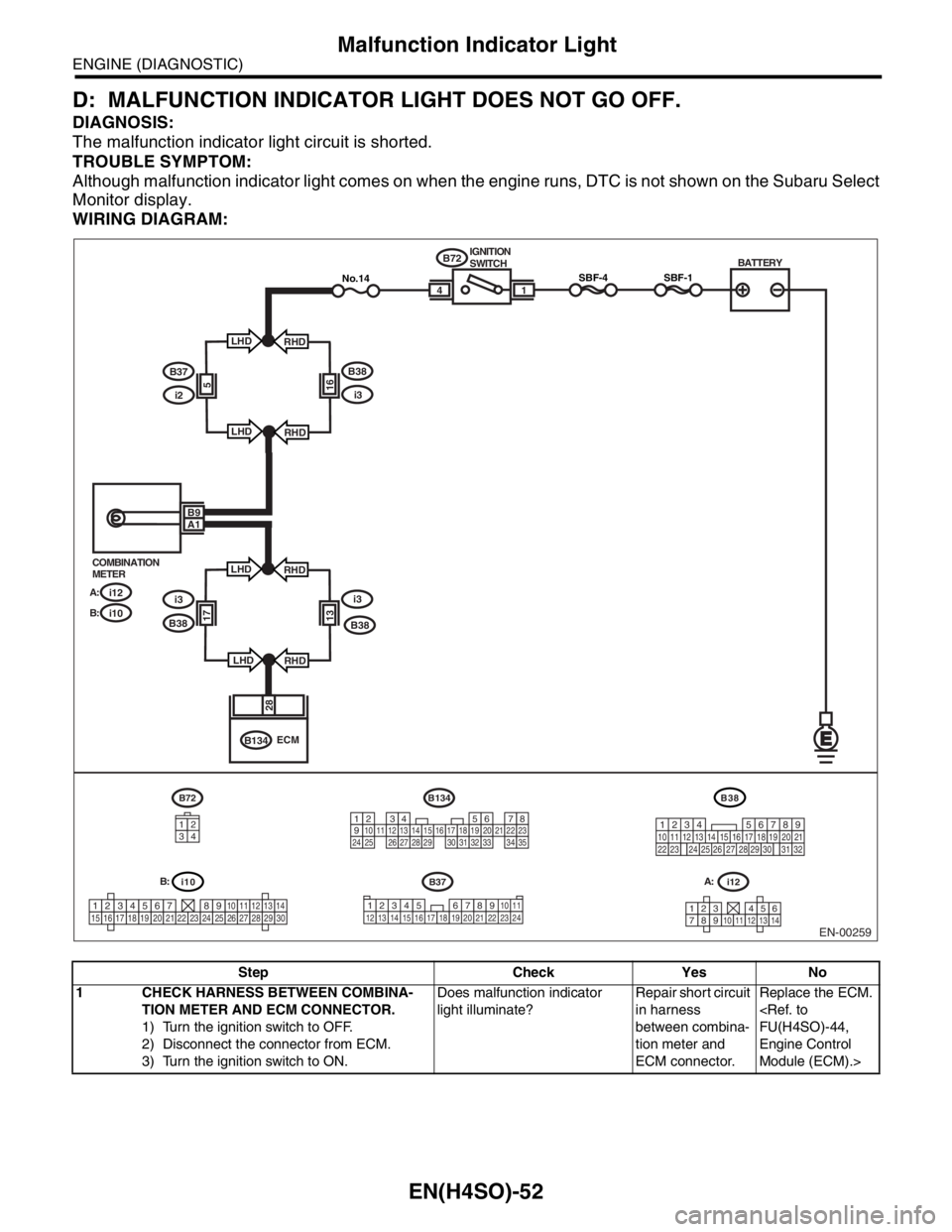
The malfunction indicator light circuit is shorted.
TROUBLE SYMPTOM:
Although malfunction indicator light comes on when the engine runs, DTC is not shown on the Subaru Select
Monitor display.
WIRING DIAGRAM:
Step Check Yes No
1 CHECK HARNESS BETWEEN COMBINA-
TION METER AND ECM CONNECTOR.
1) Turn the ignition switch to OFF.
2) Disconnect the connector from ECM.
3) Turn the ignition switch to ON.Does malfunction indicator
light illuminate?Repair short circuit
in harness
between combina-
tion meter and
ECM connector.Replace the ECM.
FU(H4SO)-44,
Engine Control
Module (ECM).>
EN-00259
i10
123456789101112131415161718192021222324252627282930
BATTERY
1
B72
B134IGNITION
SWITCH
i12 COMBINATION
METER
A:
i10 B:
SBF-44
28
ECM
B9A1
i12
1234568791011121314
B134
1234567891011121314151617181920212223242526272829303132333435
B72
34
12
SBF-1No.14
B37
34 12 8910 11
12 13 14 15 16 17 18 19 20 21 22 23 24567
B38
219
32
1234 5610 11 12 13 14 15716
23 3019 20
22 26 27 28 29817
24 3118
25
B37
i2
B38
i3165
LHD
LHDRHD
RHD
i3i3
B381317
LHD
LHDRHD
RHD B38
A: B:
Page 1151 of 2870
EN(H4SO)-53
ENGINE (DIAGNOSTIC)
Malfunction Indicator Light
E: MALFUNCTION INDICATOR LIGHT DOES NOT BLINK.
DIAGNOSIS:
The malfunction indicator light circuit is open or shorted.
Test mode connector circuit is in open.
TROUBLE SYMPTOM:
Malfunction indicator light does not blink during inspection mode.
WIRING DIAGRAM:
EN-00260
i10
123456789101112131415161718192021222324252627282930
B37
34 12 8910 11
12 13 14 15 16 17 18 19 20 21 22 23 24567
BATTERY
1
B72
B125B75B76B126 IGNITION
SWITCH
i12 COMBINATION
METER
A:
i10 B:
B134 A:
B136 C:
SBF-44
A28C3
ECM
B9A1
i12
1234568791011121314
B134
1234567891011121314151617181920212223242526272829303132333435
B72
34
12
SBF-1No.14
1
B21E2
1611
1 B125
B75
1
21
21
B21
123
4
56
78
9
1011 12
1314 15 16
B136
5
2
84
3923 20 211011
221617
24
2512136
261915
14
1
7
18
B38
219
32
1234 5610 11 12 13 14 15716
23 3019 20
22 26 27 28 29817
24 3118
25
B37
i2
B38
i3165
LHD
LHDRHD
RHD
i3i3
B381317
LHD
LHDRHD
RHD B38
A:
C:
A: B:
Page 1152 of 2870

EN(H4SO)-54
ENGINE (DIAGNOSTIC)
Malfunction Indicator Light
Step Check Yes No
1 CHECK STATUS OF MALFUNCTION INDI-
CATOR LIGHT.
1) Turn the ignition switch to OFF.
2) Disconnect the test mode connectors
3) Turn the ignition switch to ON. (engine
OFF)Does malfunction indicator
light illuminate?Go to step 2.Repair the mal-
function indictor
light circuit.
to EN(H4SO)-49,
MALFUNCTION
INDICATOR
LIGHT DOES
NOT COME ON,
Malfunction Indica-
tor Light.>
2 CHECK HARNESS BETWEEN COMBINA-
TION METER AND ECM CONNECTOR.
1) Turn the ignition switch to OFF.
2) Disconnect the connector from ECM.
3) Turn the ignition switch to ON.Does malfunction indicator
light illuminate?Repair short circuit
in harness
between combina-
tion meter and
ECM connector.Go to step 3.
3 CHECK HARNESS BETWEEN TEST MODE
CONNECTOR AND CHASSIS GROUND.
1) Turn the ignition switch to OFF.
2) Disconnect the connector from ECM.
3) Measure the resistance of harness
between test mode connector and chassis
ground.
Connector & terminal
(B76) No. 1 — Chassis ground:Is the resistance less than 1
Ω?Go to step 4.Repair harness
and connector.
N
OTE:
In this case repair
the following:
Open circuit in
harness between
test mode connec-
tor and chassis
ground
4 CHECK POOR CONTACT.
Check poor contact in ECM connector.Is there poor contact in ECM
connector?Repair the poor
contact in ECM
connector.Go to step 5.
5 CHECK HARNESS BETWEEN ECM AND
TEST MODE CONNECTOR.
1) Connect the test mode connector.
2) Measure the resistance of harness
between ECM and chassis ground.
Connector & terminal
(B136) No. 3 — Chassis ground:Is the resistance less than 1
Ω?Go to step 6.Repair open circuit
in harness
between ECM and
test mode connec-
tor.
6 CHECK POOR CONTACT.
Check poor contact in ECM connector.Is there poor contact in ECM
connector?Repair the poor
contact in ECM
connector.Replace the ECM.
FU(H4SO)-44,
Engine Control
Module (ECM).>