2004 SUBARU FORESTER spark plugs
[x] Cancel search: spark plugsPage 1070 of 2870

IG(H4SO)-6
IGNITION
Spark Plug
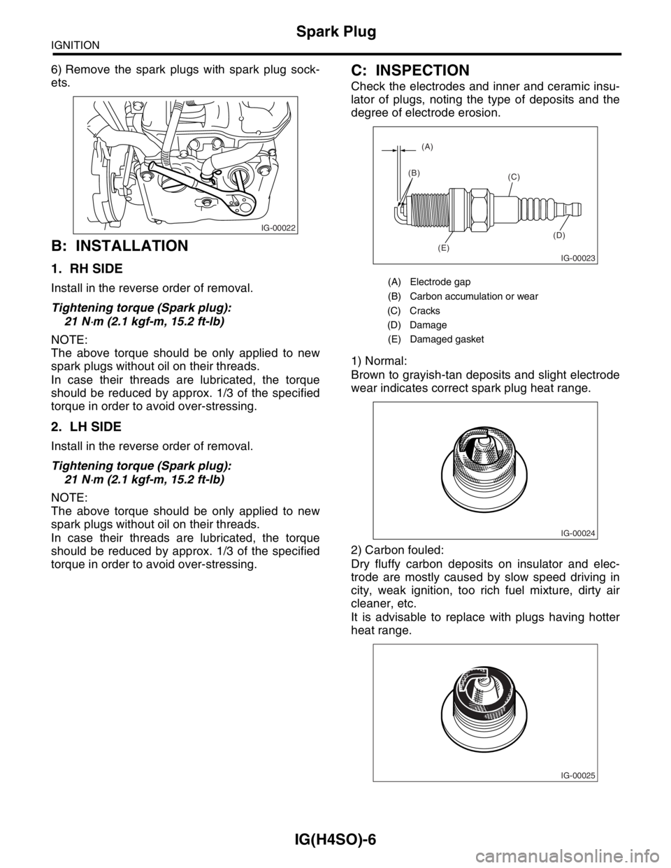
6) Remove the spark plugs with spark plug sock-
ets.
B: INSTALLATION
1. RH SIDE
Install in the reverse order of removal.
Tightening torque (Spark plug):
21 N
⋅m (2.1 kgf-m, 15.2 ft-lb)
NOTE:
The above torque should be only applied to new
spark plugs without oil on their threads.
In case their threads are lubricated, the torque
should be reduced by approx. 1/3 of the specified
torque in order to avoid over-stressing.
2. LH SIDE
Install in the reverse order of removal.
Tightening torque (Spark plug):
21 N
⋅m (2.1 kgf-m, 15.2 ft-lb)
NOTE:
The above torque should be only applied to new
spark plugs without oil on their threads.
In case their threads are lubricated, the torque
should be reduced by approx. 1/3 of the specified
torque in order to avoid over-stressing.
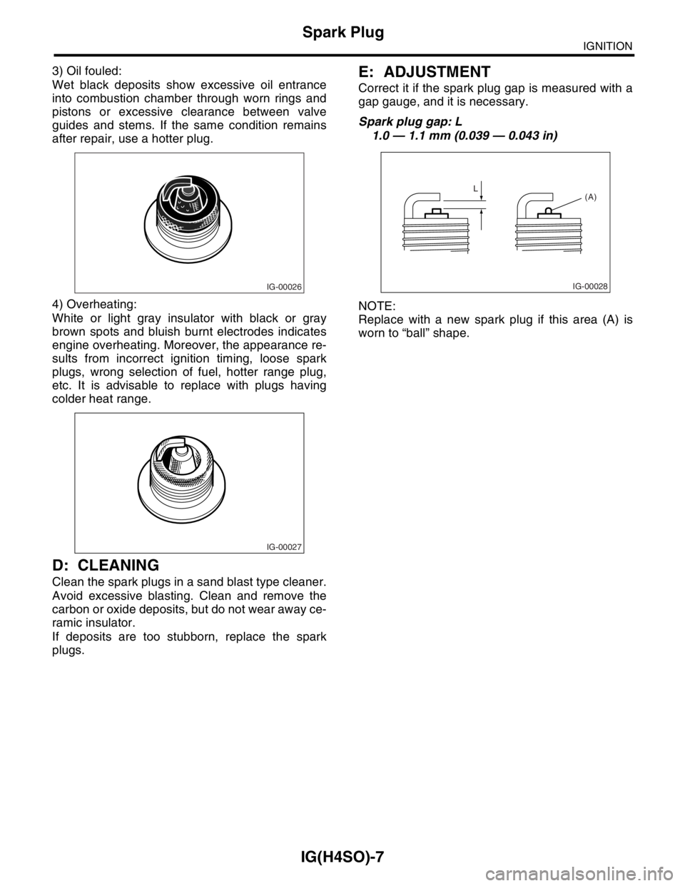
C: INSPECTION
Check the electrodes and inner and ceramic insu-
lator of plugs, noting the type of deposits and the
degree of electrode erosion.
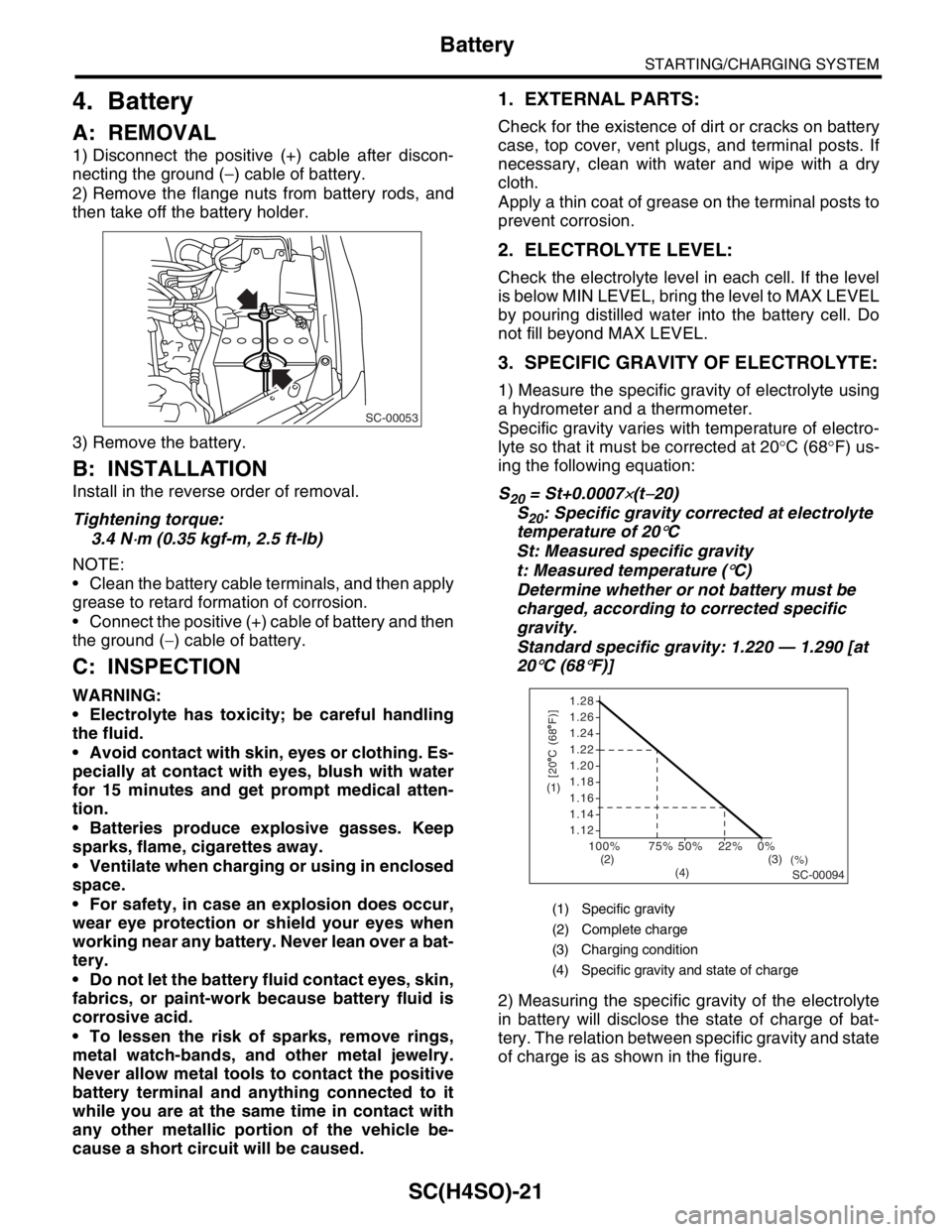
1) Normal:
Brown to grayish-tan deposits and slight electrode
wear indicates correct spark plug heat range.
2) Carbon fouled:
Dry fluffy carbon deposits on insulator and elec-
trode are mostly caused by slow speed driving in
city, weak ignition, too rich fuel mixture, dirty air
cleaner, etc.
It is advisable to replace with plugs having hotter
heat range.
IG-00022
(A) Electrode gap
(B) Carbon accumulation or wear
(C) Cracks
(D) Damage
(E) Damaged gasket
IG-00023
(A)
(B)
(C)
(D)
(E)
IG-00024
IG-00025
Page 1071 of 2870

IG(H4SO)-7
IGNITION
Spark Plug
3) Oil fouled:
Wet black deposits show excessive oil entrance
into combustion chamber through worn rings and
pistons or excessive clearance between valve
guides and stems. If the same condition remains
after repair, use a hotter plug.
4) Overheating:
White or light gray insulator with black or gray
brown spots and bluish burnt electrodes indicates
engine overheating. Moreover, the appearance re-
sults from incorrect ignition timing, loose spark
plugs, wrong selection of fuel, hotter range plug,
etc. It is advisable to replace with plugs having
colder heat range.
D: CLEANING
Clean the spark plugs in a sand blast type cleaner.
Avoid excessive blasting. Clean and remove the
carbon or oxide deposits, but do not wear away ce-
ramic insulator.
If deposits are too stubborn, replace the spark
plugs.
E: ADJUSTMENT
Correct it if the spark plug gap is measured with a
gap gauge, and it is necessary.
Spark plug gap: L
1.0 — 1.1 mm (0.039 — 0.043 in)
NOTE:
Replace with a new spark plug if this area (A) is
worn to “ball” shape.
IG-00026
IG-00027
IG-00028
L
(A)
Page 1096 of 2870

SC(H4SO)-21
STARTING/CHARGING SYSTEM
Battery
4. Battery
A: REMOVAL
1) Disconnect the positive (+) cable after discon-
necting the ground (−) cable of battery.
2) Remove the flange nuts from battery rods, and
then take off the battery holder.
3) Remove the battery.
B: INSTALLATION
Install in the reverse order of removal.
Tightening torque:
3.4 N
⋅m (0.35 kgf-m, 2.5 ft-lb)
NOTE:
Clean the battery cable terminals, and then apply
grease to retard formation of corrosion.
Connect the positive (+) cable of battery and then
the ground (−) cable of battery.
C: INSPECTION
WARNING:
Electrolyte has toxicity; be careful handling
the fluid.
Avoid contact with skin, eyes or clothing. Es-
pecially at contact with eyes, blush with water
for 15 minutes and get prompt medical atten-
tion.
Batteries produce explosive gasses. Keep
sparks, flame, cigarettes away.
Ventilate when charging or using in enclosed
space.
For safety, in case an explosion does occur,
wear eye protection or shield your eyes when
working near any battery. Never lean over a bat-
tery.
Do not let the battery fluid contact eyes, skin,
fabrics, or paint-work because battery fluid is
corrosive acid.
To lessen the risk of sparks, remove rings,
metal watch-bands, and other metal jewelry.
Never allow metal tools to contact the positive
battery terminal and anything connected to it
while you are at the same time in contact with
any other metallic portion of the vehicle be-
cause a short circuit will be caused.
1. EXTERNAL PARTS:
Check for the existence of dirt or cracks on battery
case, top cover, vent plugs, and terminal posts. If
necessary, clean with water and wipe with a dry
cloth.
Apply a thin coat of grease on the terminal posts to
prevent corrosion.
2. ELECTROLYTE LEVEL:
Check the electrolyte level in each cell. If the level
is below MIN LEVEL, bring the level to MAX LEVEL
by pouring distilled water into the battery cell. Do
not fill beyond MAX LEVEL.
3. SPECIFIC GRAVITY OF ELECTROLYTE:
1) Measure the specific gravity of electrolyte using
a hydrometer and a thermometer.
Specific gravity varies with temperature of electro-
lyte so that it must be corrected at 20°C (68°F) us-
ing the following equation:
S
20 = St+0.0007×(t−20)
S
20: Specific gravity corrected at electrolyte
temperature of 20
°C
St: Measured specific gravity
t: Measured temperature (
°C)
Determine whether or not battery must be
charged, according to corrected specific
gravity.
Standard specific gravity: 1.220 — 1.290 [at
20
°C (68°F)]
2) Measuring the specific gravity of the electrolyte
in battery will disclose the state of charge of bat-
tery. The relation between specific gravity and state
of charge is as shown in the figure.
SC-00053
(1) Specific gravity
(2) Complete charge
(3) Charging condition
(4) Specific gravity and state of charge
1.28
1.26
1.24
1.22
1.20
1.18
1.16
1.14
1.12
100%
(%)75% 50% 22% 0%
SC-00094
[20 C (68 F)](1)
(2) (3)
(4)
Page 1487 of 2870

ME(H4DOTC)-31
MECHANICAL
Compression
2. Compression
A: INSPECTION
CAUTION:
After warming-up, engine becomes very hot. Be
careful not to burn yourself during measure-
ment.
1) After warming-up the engine, turn the ignition
switch to OFF.
2) Make sure that the battery is fully charged.
3) Release the fuel pressure.
SURE, OPERATION, Fuel.>
4) Remove all the spark plugs.
5) Fully open the throttle valve.
6) Check the starter motor for satisfactory perfor-
mance and operation.
7) Hold the compression gauge tight against spark
plug hole.
NOTE:
When using a screw-in type compression gauge,
the screw (put into cylinder head spark plug hole)
should be less than 18 mm (0.71 in) long.
8) Crank the engine by means of starter motor, and
then read the maximum value on the gauge when
the pointer is steady.9) Perform at least two measurements per cylinder,
and make sure that the values are correct.
Compression (350 rpm and fully open throttle):
Standard
981 — 1,177 kPa (10 — 12 kgf/cm
2, 142 —
171 psi)
Limit
882 kPa (9.0 kgf/cm
2, 128 psi)
Difference between cylinders
Less than 49 kPa (0.5 kgf/cm
2, 7 psi)
ME-00007
Page 1488 of 2870

ME(H4DOTC)-32
MECHANICAL
Idle Speed
3. Idle Speed
A: INSPECTION
1. USING SUBARU SELECT MONITOR
1) Before checking the idle speed, check the fol-
lowing:
(1) Ensure the air cleaner element is free from
clogging, ignition timing is correct, spark plugs
are in good condition, and that the hoses are
connected properly.
(2) Ensure the malfunction indicator light does
not illuminate.
2) Warm-up the engine.
3) Stop the engine, and then turn the ignition switch
to OFF.
4) Insert the cartridge to Subaru Select Monitor.
5) Connect the Subaru Select Monitor to data link
connector.
6) Turn the ignition switch to ON, and Subaru Se-
lect Monitor switch to ON.
7) Select the {2. Each System Check} in Main
Menu.
8) Select the {Engine Control System} in Selection
Menu.
9) Select the {1. Current Data Display & Save} in
Engine Control System Diagnosis.
10) Select the {1.12 Data Display} in Data Display
Menu.
11) Start the engine, and then read the engine idle
speed.
12) Check the idle speed when unloaded. (With
headlights, heater fan, rear defroster, radiator fan,
air conditioning, etc. OFF)
Idle speed [No load and gears in neutral]:
700
±100 rpm
13) Check the idle speed when loaded. (Turn the
air conditioning switch to “ON” and operate the
compressor for at least 1 minute before measure-
ment.)
Idle speed [A/C “ON”, no load and gears in neu-
tral]:
A/C Refrigerant pressure (LOW)
MT: 725
±100 rpm
AT: 750
±100 rpm
A/C Refrigerant pressure (HIGH)
MT: 800
±100 rpm
AT: 825
±100 rpm
NOTE:
As idle speed is controlled by the automatic adjust-
ment type, it can not be adjusted manually. If the
idle speed is out of specifications, refer to General
On-board Diagnosis Table under “Engine Control
System”.
Page 1489 of 2870

ME(H4DOTC)-33
MECHANICAL
Ignition Timing
4. Ignition Timing
A: INSPECTION
1. USING SUBARU SELECT MONITOR
1) Before checking the ignition timing speed, check
the following:
(1) Ensure the air cleaner element is free from
clogging, spark plugs are in good condition, and
that hoses are connected properly.
(2) Ensure the malfunction indicator light does
not illuminate.
2) Warm-up the engine.
3) Stop the engine, and then turn the ignition switch
to OFF.
4) Insert the cartridge to Subaru Select Monitor.
5) Connect the Subaru Select Monitor to data link
connector.
6) Turn the ignition switch to ON, and Subaru Se-
lect Monitor switch to ON.
7) Select the {2. Each System Check} in Main
Menu.
8) Select the {Engine Control System} in Selection
Menu.
9) Select the {1. Current Data Display & Save} in
Engine Control System Diagnosis.
10) Select the {1.12 Data Display} in Data Display
Menu.
11) Start the engine and check the ignition timing at
idle speed.
Ignition timing [BTDC/rpm]:
2.0 L model
12
°±10°/700
2.5 L model
17
°±10°/700
If the timing is not correct, check the ignition control
system. Refer to Engine Control System.
Page 1578 of 2870

ME(H4DOTC)-118
MECHANICAL
Engine Trouble in General
25.Engine Trouble in General
A: INSPECTION
NOTE:
“RANK” shown in the chart refers to the possibility of reason for the trouble in order (“Very often” to “Rarely”)
A — Very often
B — Sometimes
C — Rarely
TROUBLE PROBLEM PARTS, ETC. POSSIBLE CAUSE RANK
1. Engine will not start.
1) Starter does not turn. Starter Defective battery-to-starter harness B
Defective starter switch C
Defective inhibitor switch or neutral switch C
Defective starter B
Battery Poor terminal connection A
Run-down battery A
Defective charging system B
Friction Seizure of crankshaft and connecting rod bearing C
Seized camshaft C
Seized or stuck piston and cylinder C
2) Initial combustion does
not occur. Starter Defective starter C
Engine control system
Fuel line Defective fuel pump and relay A
Lack of or insufficient fuel B
Belt Defective (deterioration, etc.) B
Defective timing B
Compression Incorrect valve clearance C
Loosened spark plugs or defective gasket C
Loosened cylinder head bolts or defective gasket C
Improper valve seating C
Defective valve stem C
Worn or broken valve spring B
Worn or stuck piston rings, cylinder and piston C
Incorrect valve timing B
Improper engine oil (low viscosity) B
3) Initial combustion occurs. Engine control system
Intake system Defective intake manifold gasket B
Defective throttle body gasket B
Fuel line Defective fuel pump and relay C
Clogged fuel line C
Lack of or insufficient fuel B
Belt Defective (deterioration, etc.) B
Defective timing B
Compression Incorrect valve clearance C
Loosened spark plugs or defective gasket C
Loosened cylinder head bolts or defective gasket C
Improper valve seating C
Defective valve stem C
Worn or broken valve spring B
Worn or stuck piston rings, cylinder and piston C
Incorrect valve timing B
Improper engine oil (low viscosity) B
Page 1579 of 2870

ME(H4DOTC)-119
MECHANICAL
Engine Trouble in General
4) Engine stalls after initial
combustion. Engine control system
Intake system Loosened or cracked intake duct B
Loosened or cracked PCV hose C
Loosened or cracked vacuum hose C
Defective intake manifold gasket B
Defective throttle body gasket B
Dirty air cleaner element C
Fuel line Clogged fuel line C
Lack of or insufficient fuel B
Belt Defective (deterioration, etc.) B
Defective timing B
Compression Incorrect valve clearance C
Loosened spark plugs or defective gasket C
Loosened cylinder head bolts or defective gasket C
Improper valve seating C
Defective valve stem C
Worn or broken valve spring B
Worn or stuck piston rings, cylinder and piston C
Incorrect valve timing B
Improper engine oil (low viscosity) B
2. Rough idle and engine
stallEngine control system
Intake system Loosened or cracked intake duct A
Loosened or cracked PCV hose A
Loosened or cracked vacuum hose A
Defective intake manifold gasket B
Defective throttle body gasket B
Defective PCV valve C
Loosened oil filler cap B
Dirty air cleaner element C
Fuel line Defective fuel pump and relay C
Clogged fuel line C
Lack of or insufficient fuel B
Belt Defective timing C
Compression Incorrect valve clearance B
Loosened spark plugs or defective gasket B
Loosened cylinder head bolts or defective gasket B
Improper valve seating B
Defective valve stem C
Worn or broken valve spring B
Worn or stuck piston rings, cylinder and piston B
Incorrect valve timing A
Improper engine oil (low viscosity) B
Lubrication system Incorrect oil pressure B
Defective rocker cover gasket C
Cooling system Overheating C
Others Malfunction of evaporative emission control system A
Stuck or damaged throttle valve B
Accelerator cable out of adjustment C TROUBLE PROBLEM PARTS, ETC. POSSIBLE CAUSE RANK