Page 440 of 2870
SL-20
SECURITY AND LOCK
Keyless Entry System
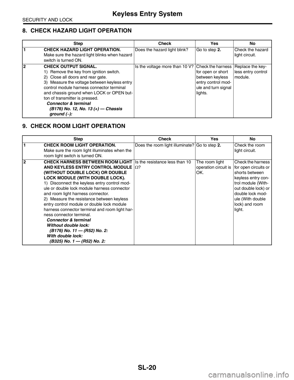
8. CHECK HAZARD LIGHT OPERATION
9. CHECK ROOM LIGHT OPERATION
Step Check Yes No
1 CHECK HAZARD LIGHT OPERATION.
Make sure the hazard light blinks when hazard
switch is turned ON.Does the hazard light blink? Go to step 2.Check the hazard
light circuit.
2 CHECK OUTPUT SIGNAL.
1) Remove the key from ignition switch.
2) Close all doors and rear gate.
3) Measure the voltage between keyless entry
control module harness connector terminal
and chassis ground when LOCK or OPEN but-
ton of transmitter is pressed.
Connector & terminal
(B176) No. 12, No. 13 (+) — Chassis
ground (
−):Is the voltage more than 10 V? Check the harness
for open or short
between keyless
entry control mod-
ule and turn signal
lights.Replace the key-
less entry control
module.
Step Check Yes No
1 CHECK ROOM LIGHT OPERATION.
Make sure the room light illuminates when the
room light switch is turned ON.Does the room light illuminate? Go to step 2.Check the room
light circuit.
2 CHECK HARNESS BETWEEN ROOM LIGHT
AND KEYLESS ENTRY CONTROL MODULE
(WITHOUT DOUBLE LOCK) OR DOUBLE
LOCK MODULE (WITH DOUBLE LOCK).
1) Disconnect the keyless entry control mod-
ule or double lock module harness connector
and room light harness connector.
2) Measure the resistance between keyless
entry control module or double lock module
harness connector terminal and room light har-
ness connector terminal.
Connector & terminal
Without double lock:
(B176) No. 11 — (R52) No. 2:
With double lock:
(B325) No. 1 — (R52) No. 2:Is the resistance less than 10
Ω?The room light
operation circuit is
OK.Check the harness
for open circuits or
shorts between
keyless entry con-
trol module (With-
out double lock) or
double lock mod-
ule (With double
lock) and room
light.
Page 441 of 2870
SL-21
SECURITY AND LOCK
Keyless Entry System
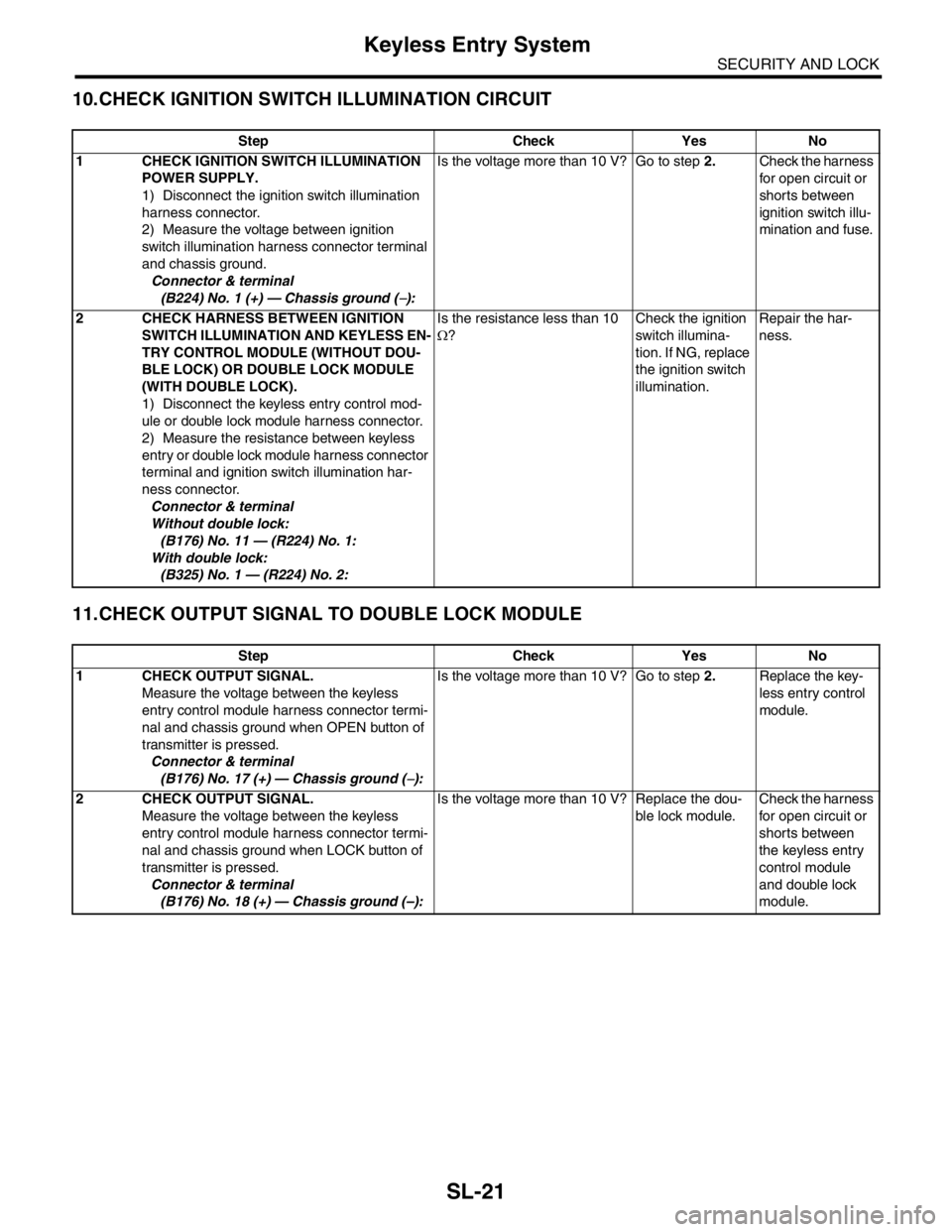
10.CHECK IGNITION SWITCH ILLUMINATION CIRCUIT
11.CHECK OUTPUT SIGNAL TO DOUBLE LOCK MODULE
Step Check Yes No
1 CHECK IGNITION SWITCH ILLUMINATION
POWER SUPPLY.
1) Disconnect the ignition switch illumination
harness connector.
2) Measure the voltage between ignition
switch illumination harness connector terminal
and chassis ground.
Connector & terminal
(B224) No. 1 (+) — Chassis ground (
−):Is the voltage more than 10 V? Go to step 2.Check the harness
for open circuit or
shorts between
ignition switch illu-
mination and fuse.
2 CHECK HARNESS BETWEEN IGNITION
SWITCH ILLUMINATION AND KEYLESS EN-
TRY CONTROL MODULE (WITHOUT DOU-
BLE LOCK) OR DOUBLE LOCK MODULE
(WITH DOUBLE LOCK).
1) Disconnect the keyless entry control mod-
ule or double lock module harness connector.
2) Measure the resistance between keyless
entry or double lock module harness connector
terminal and ignition switch illumination har-
ness connector.
Connector & terminal
Without double lock:
(B176) No. 11 — (R224) No. 1:
With double lock:
(B325) No. 1 — (R224) No. 2:Is the resistance less than 10
Ω?Check the ignition
switch illumina-
tion. If NG, replace
the ignition switch
illumination.Repair the har-
ness.
Step Check Yes No
1 CHECK OUTPUT SIGNAL.
Measure the voltage between the keyless
entry control module harness connector termi-
nal and chassis ground when OPEN button of
transmitter is pressed.
Connector & terminal
(B176) No. 17 (+) — Chassis ground (
−):Is the voltage more than 10 V? Go to step 2.Replace the key-
less entry control
module.
2 CHECK OUTPUT SIGNAL.
Measure the voltage between the keyless
entry control module harness connector termi-
nal and chassis ground when LOCK button of
transmitter is pressed.
Connector & terminal
(B176) No. 18 (+) — Chassis ground (–):Is the voltage more than 10 V? Replace the dou-
ble lock module.Check the harness
for open circuit or
shorts between
the keyless entry
control module
and double lock
module.
Page 455 of 2870
SL-35
SECURITY AND LOCK
Ignition Key Lock
17.Ignition Key Lock
A: REPLACEMENT
1) Remove the ground cable from battery.
2) Remove the steering column.
REMOVAL, Tilt Steering Column.>
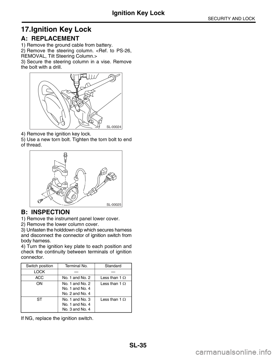
3) Secure the steering column in a vise. Remove
the bolt with a drill.
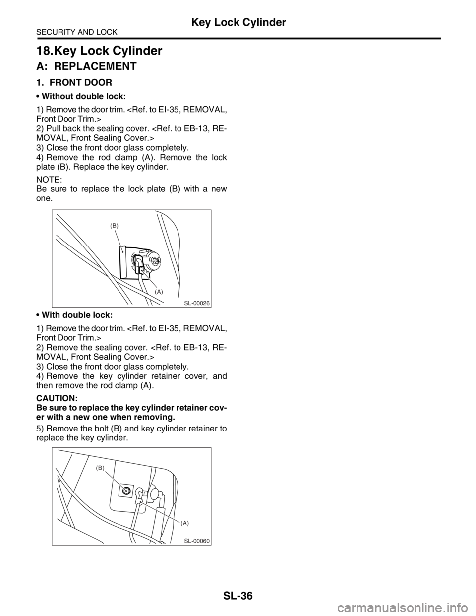
4) Remove the ignition key lock.
5) Use a new torn bolt. Tighten the torn bolt to end
of thread.
B: INSPECTION
1) Remove the instrument panel lower cover.
2) Remove the lower column cover.
3) Unfasten the holddown clip which secures harness
and disconnect the connector of ignition switch from
body harness.
4) Turn the ignition key plate to each position and
check the continuity between terminals of ignition
connector.
If NG, replace the ignition switch.
Switch position Terminal No. Standard
LOCK — —
ACC No. 1 and No. 2 Less than 1 Ω
ON No. 1 and No. 2
No. 1 and No. 4
No. 2 and No. 4Less than 1 Ω
ST No. 1 and No. 3
No. 1 and No. 4
No. 3 and No. 4Less than 1 Ω
SL-00024
SL-00025
Page 456 of 2870
SL-36
SECURITY AND LOCK
Key Lock Cylinder
18.Key Lock Cylinder
A: REPLACEMENT
1. FRONT DOOR
Without double lock:
1) Remove the door trim.
Front Door Trim.>
2) Pull back the sealing cover.
MOVAL, Front Sealing Cover.>
3) Close the front door glass completely.
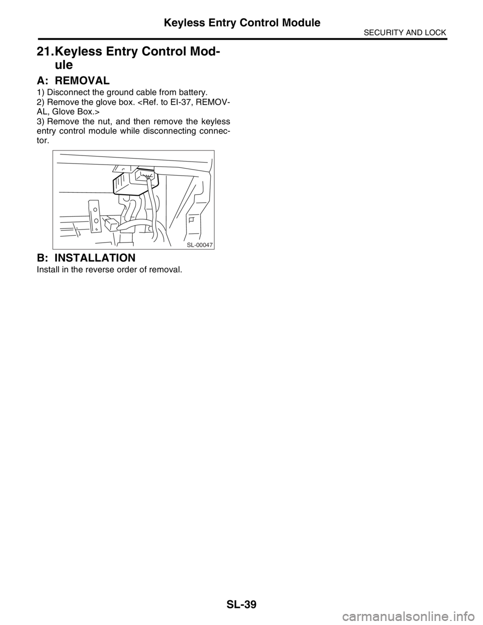
4) Remove the rod clamp (A). Remove the lock
plate (B). Replace the key cylinder.
NOTE:
Be sure to replace the lock plate (B) with a new
one.
With double lock:
1) Remove the door trim.
Front Door Trim.>
2) Remove the sealing cover.
MOVAL, Front Sealing Cover.>
3) Close the front door glass completely.
4) Remove the key cylinder retainer cover, and
then remove the rod clamp (A).
CAUTION:
Be sure to replace the key cylinder retainer cov-
er with a new one when removing.
5) Remove the bolt (B) and key cylinder retainer to
replace the key cylinder.
SL-00026
(A) (B)
SL-00060
(A) (B)
Page 459 of 2870
SL-39
SECURITY AND LOCK
Keyless Entry Control Module
21.Keyless Entry Control Mod-
ule
A: REMOVAL
1) Disconnect the ground cable from battery.
2) Remove the glove box.
AL, Glove Box.>
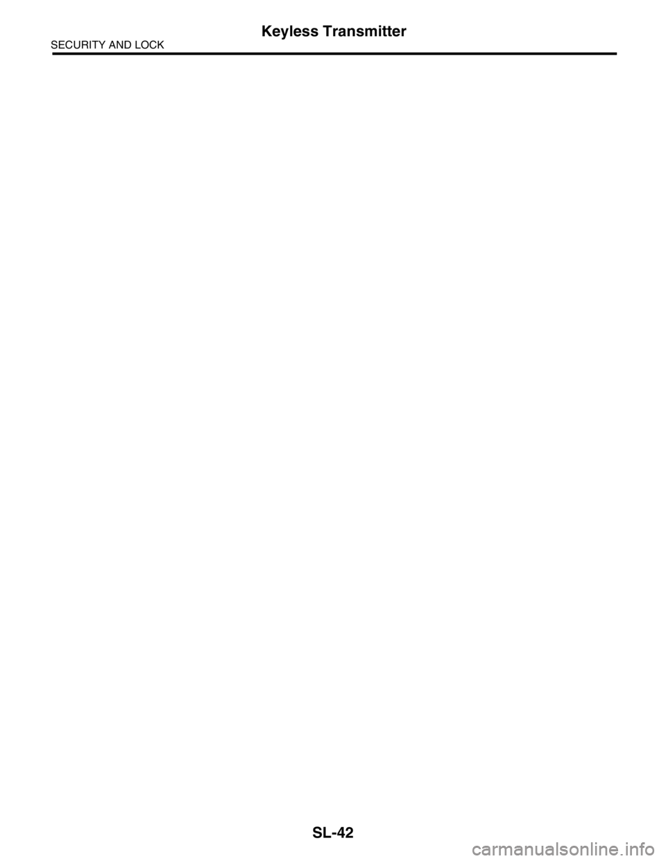
3) Remove the nut, and then remove the keyless
entry control module while disconnecting connec-
tor.
B: INSTALLATION
Install in the reverse order of removal.
SL-00047
Page 461 of 2870
SL-41
SECURITY AND LOCK
Keyless Transmitter
23.Keyless Transmitter
A: REMOVAL
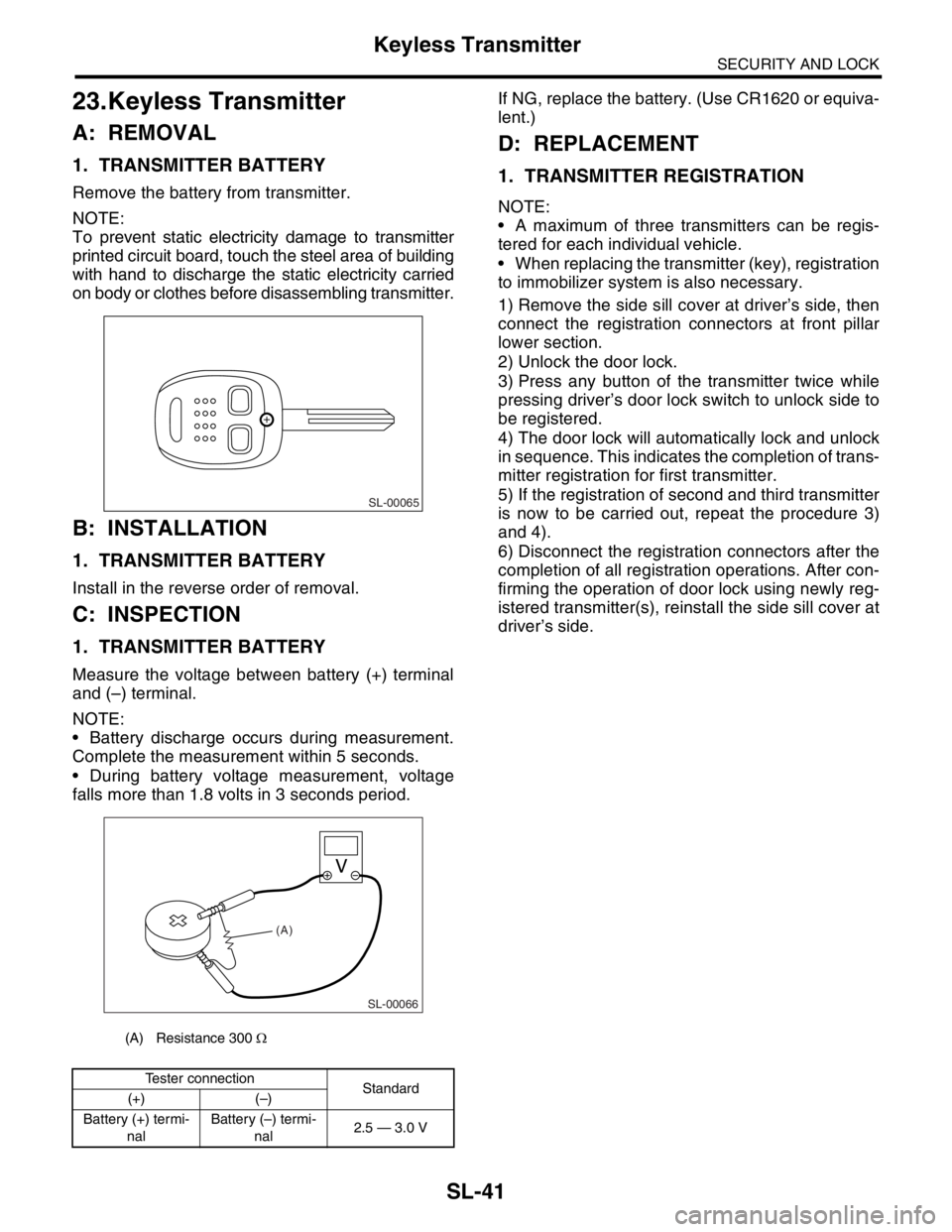
1. TRANSMITTER BATTERY
Remove the battery from transmitter.
NOTE:
To prevent static electricity damage to transmitter
printed circuit board, touch the steel area of building
with hand to discharge the static electricity carried
on body or clothes before disassembling transmitter.
B: INSTALLATION
1. TRANSMITTER BATTERY
Install in the reverse order of removal.
C: INSPECTION
1. TRANSMITTER BATTERY
Measure the voltage between battery (+) terminal
and (–) terminal.
NOTE:
Battery discharge occurs during measurement.
Complete the measurement within 5 seconds.
During battery voltage measurement, voltage
falls more than 1.8 volts in 3 seconds period.If NG, replace the battery. (Use CR1620 or equiva-
lent.)
D: REPLACEMENT
1. TRANSMITTER REGISTRATION
NOTE:
A maximum of three transmitters can be regis-
tered for each individual vehicle.
When replacing the transmitter (key), registration
to immobilizer system is also necessary.
1) Remove the side sill cover at driver’s side, then
connect the registration connectors at front pillar
lower section.
2) Unlock the door lock.
3) Press any button of the transmitter twice while
pressing driver’s door lock switch to unlock side to
be registered.
4) The door lock will automatically lock and unlock
in sequence. This indicates the completion of trans-
mitter registration for first transmitter.
5) If the registration of second and third transmitter
is now to be carried out, repeat the procedure 3)
and 4).
6) Disconnect the registration connectors after the
completion of all registration operations. After con-
firming the operation of door lock using newly reg-
istered transmitter(s), reinstall the side sill cover at
driver’s side.
(A) Resistance 300 Ω
Tester connection
Standard
(+) (–)
Battery (+) termi-
nalBattery (–) termi-
nal2.5 — 3.0 V
SL-00065
SL-00066
(A)
Page 462 of 2870
SL-42
SECURITY AND LOCK
Keyless Transmitter
Page 535 of 2870
EB-5
EXTERIOR BODY PANEL
General Description
3. FRONT DOOR PANEL
(1) Gusset (9) Upper hingeTightening torque: N·m (kgf-m, ft-lb)
(2) Weather strip (10) Key cylinder (Driver’s side only)T1: 7.5 (0.76, 5.5)
(3) Stabilizer (Outer) (11) Front sashT2: 14 (1.4, 10.3)
(4) Stabilizer (Inner) (12) Rear sashT3: 25 (2.5, 18)
(5) Door panel (13) Guide railT4: 30 (3.1, 22)
(6) CheckerT5: 33 (3.4, 24)
(7) Sealing cover T6: 6 (0.6, 4.4)
(8) Lower hinge T7: 1.5 (0.15, 1.1)
EB-00183
T1
T6
T6
T3
T3
T4
T5
T4(4) (2)
(1)
(9)(5)
(6)
(13)
(12)(7)
(11) (8)(10)
T6
T6
T2
T2
T2
T2
T1
(3)
T7