Page 476 of 2870
2004 FORESTER SERVICE MANUAL QUICK REFERENCE INDEX
BODY SECTION
G8080GE7
CRUISE CONTROL SYSTEM CC
CRUISE CONTROL SYSTEM
(DIAGNOSTIC)CC(H4SO)
CRUISE CONTROL SYSTEM
(DIAGNOSTIC)CC(H4DOTC)
CRUISE CONTROL SYSTEM
(DIAGNOSTIC)CC(H4DOTC 2.5)
IMMOBILIZER (DIAGNOSTIC) IM
Page 530 of 2870
2004 FORESTER SERVICE MANUAL QUICK REFERENCE INDEX
BODY SECTION
G8080GE7
CRUISE CONTROL SYSTEM CC
CRUISE CONTROL SYSTEM
(DIAGNOSTIC)CC(H4SO)
CRUISE CONTROL SYSTEM
(DIAGNOSTIC)CC(H4DOTC)
CRUISE CONTROL SYSTEM
(DIAGNOSTIC)CC(H4DOTC 2.5)
IMMOBILIZER (DIAGNOSTIC) IM
Page 552 of 2870
2004 FORESTER SERVICE MANUAL QUICK REFERENCE INDEX
BODY SECTION
G8080GE7
CRUISE CONTROL SYSTEM CC
CRUISE CONTROL SYSTEM
(DIAGNOSTIC)CC(H4SO)
CRUISE CONTROL SYSTEM
(DIAGNOSTIC)CC(H4DOTC)
CRUISE CONTROL SYSTEM
(DIAGNOSTIC)CC(H4DOTC 2.5)
IMMOBILIZER (DIAGNOSTIC) IM
Page 553 of 2870

CRUISE CONTROL SYSTEM
CC
Page
1. General Description ....................................................................................2
2. Actuator .......................................................................................................5
3. Cruise Control Module ................................................................................7
4. Cruise Control Main Switch .........................................................................8
5. Cruise Control Command Switch ................................................................9
6. Stop and Brake Switch ..............................................................................10
7. Clutch Switch ............................................................................................11
8. Inhibitor Switch (AT model) .......................................................................12
9. Neutral Position Switch (MT model) ..........................................................13
Page 554 of 2870
CC-2
CRUISE CONTROL SYSTEM
General Description
1. General Description
A: COMPONENT
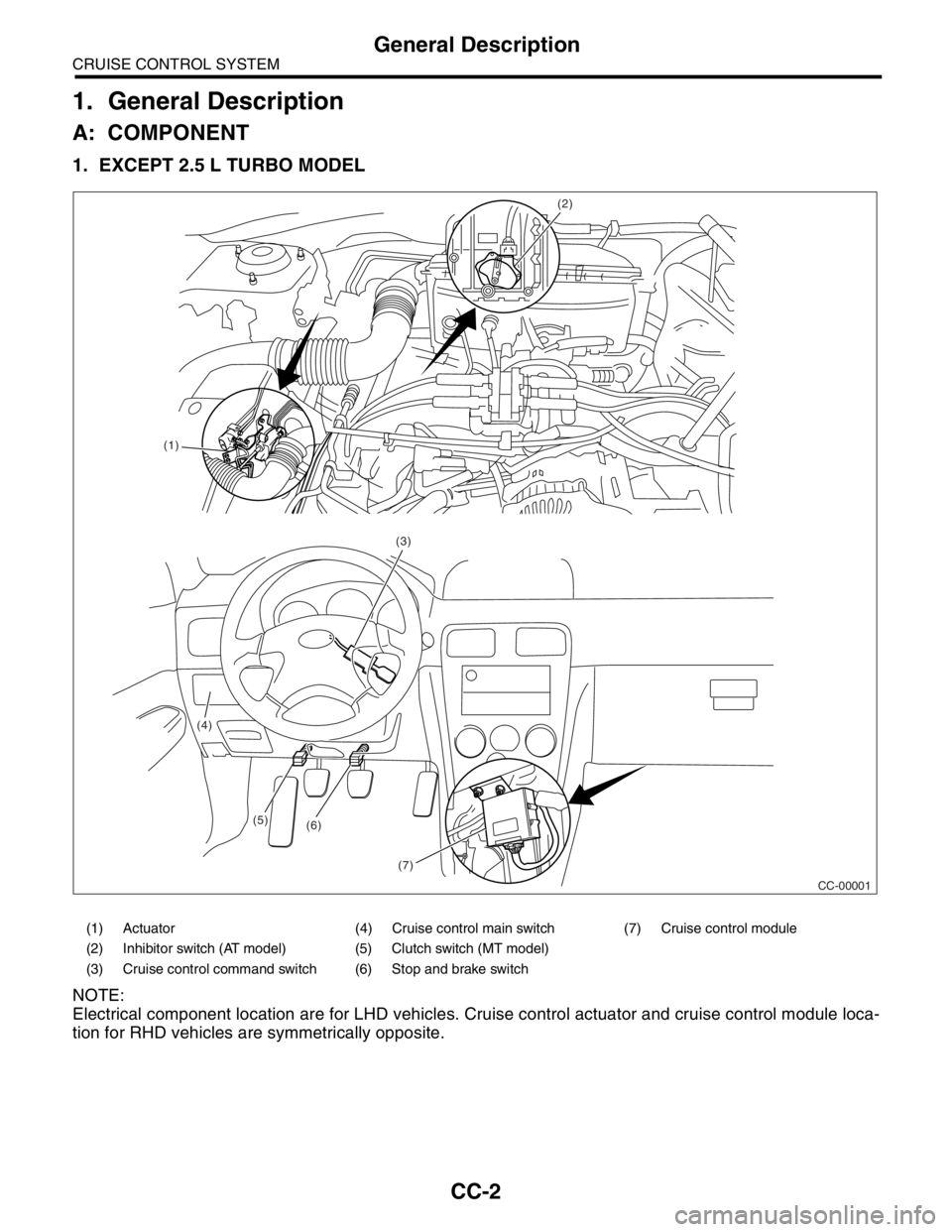
1. EXCEPT 2.5 L TURBO MODEL
NOTE:
Electrical component location are for LHD vehicles. Cruise control actuator and cruise control module loca-
tion for RHD vehicles are symmetrically opposite.
(1)(2)
(3)
(4)
(5)
(6)
(7)
CC-00001
(1) Actuator (4) Cruise control main switch (7) Cruise control module
(2) Inhibitor switch (AT model) (5) Clutch switch (MT model)
(3) Cruise control command switch (6) Stop and brake switch
Page 555 of 2870
CC-3
CRUISE CONTROL SYSTEM
General Description
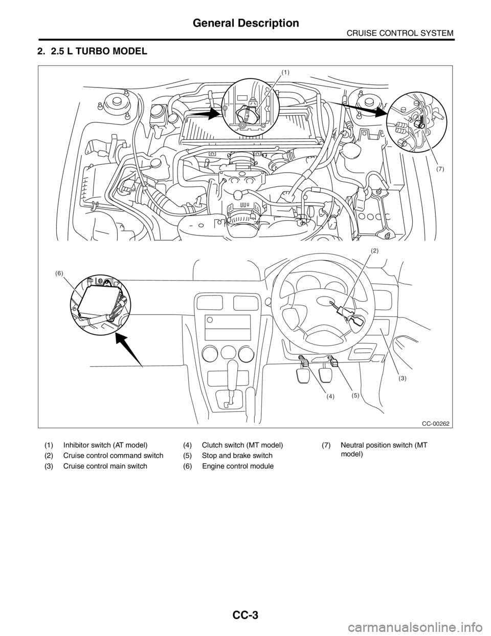
2. 2.5 L TURBO MODEL
(1)
(2)
(3)
(4) (6)(7)
CC-00262 (5)
(1) Inhibitor switch (AT model) (4) Clutch switch (MT model) (7) Neutral position switch (MT
model)
(2) Cruise control command switch (5) Stop and brake switch
(3) Cruise control main switch (6) Engine control module
Page 556 of 2870
CC-4
CRUISE CONTROL SYSTEM
General Description
B: CAUTION
Before disassembling or reassembling parts, al-
ways disconnect the battery ground cable. When re-
pairing the radio, control module and other parts with
memory functions, make note of the memory before
disconnecting the battery ground cable. All memory
will be erased.
Reassemble parts in the reverse order of disas-
sembly unless otherwise indicated.
Adjust parts to specifications specified in this man-
ual.
Connect the connectors and hoses securely dur-
ing reassembly.
After reassembly, ensure functional parts operate
properly.
C: PREPARATION TOOL
TOOL NAME REMARKS
Circuit Tester Used for measuring resis-
tance and voltage.
Page 557 of 2870
CC-5
CRUISE CONTROL SYSTEM
Actuator
2. Actuator
A: REMOVAL
CAUTION:
Be careful not to apply excessive load to the
wire cable when adjusting and/or installing; oth-
erwise, the actuator may be deformed or dam-
aged.
Do not bend the cable sharply with a radius
less than 100 mm (3.94 in); otherwise, cable
may bend permanently, resulting in poor per-
formance.
When installing the cable, be careful not to
sharply bend or pinch the inner cable; other-
wise, the cable may break.
1) Disconnect the ground cable from battery.
2) Remove the clip bands from cruise control cable.
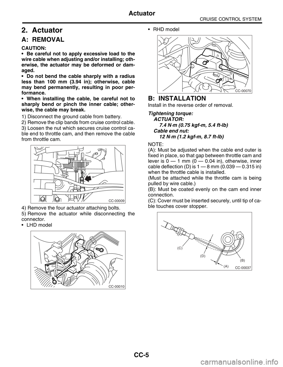
3) Loosen the nut which secures cruise control ca-
ble end to throttle cam, and then remove the cable
from throttle cam.
4) Remove the four actuator attaching bolts.
5) Remove the actuator while disconnecting the
connector.
LHD model RHD model
B: INSTALLATION
Install in the reverse order of removal.
Tightening torque:
ACTUATOR:
7.4 N
⋅m (0.75 kgf-m, 5.4 ft-lb)
Cable end nut:
12 N
⋅m (1.2 kgf-m, 8.7 ft-lb)
NOTE:
(A): Must be adjusted when the cable end outer is
fixed in place, so that gap between throttle cam and
lever is 0 — 1 mm (0 — 0.04 in), otherwise, inner
cable deflection (D) is 1 — 8 mm (0.039 — 0.315 in)
when the throttle cable is installed.
(Must be attached while the throttle cam is being
pulled by wire cable.)
(B): Must be coated evenly on the cam end inner
connection.
(C): Cover must be inserted securely, until tip of ca-
ble touches cover stopper.
CC-00009
CC-00010
CC-00070
CC-00037
(B)
(A) (D) (C)