Page 558 of 2870
CC-6
CRUISE CONTROL SYSTEM
Actuator
C: INSPECTION
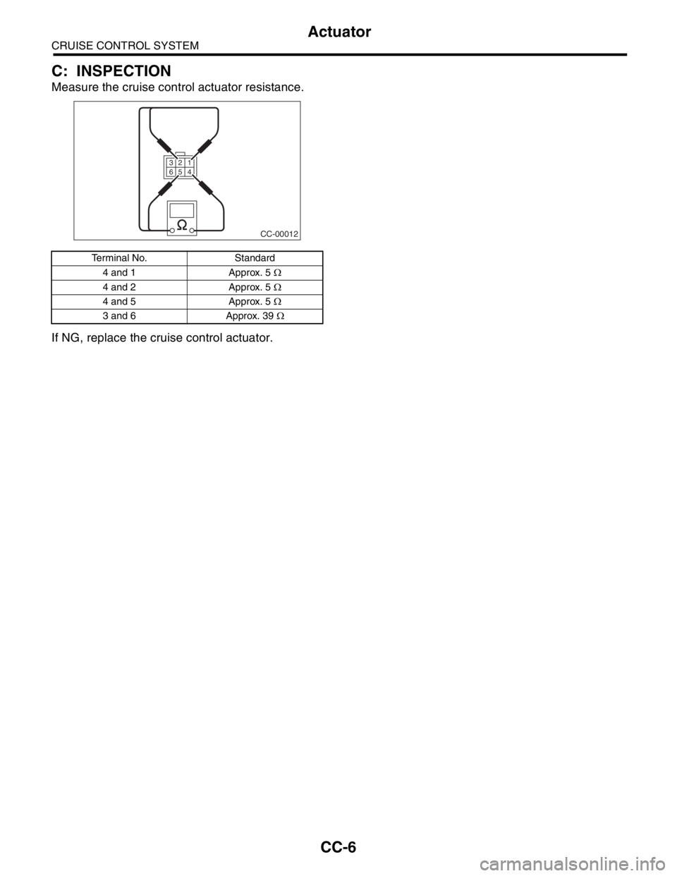
Measure the cruise control actuator resistance.
If NG, replace the cruise control actuator.
Terminal No. Standard
4 and 1 Approx. 5 Ω
4 and 2 Approx. 5 Ω
4 and 5 Approx. 5 Ω
3 and 6 Approx. 39 Ω
CC-00012
1 3
4 5 62
Page 559 of 2870
CC-7
CRUISE CONTROL SYSTEM
Cruise Control Module
3. Cruise Control Module
A: NOTE
Engine Control Module (ECM) controls cruise con-
trol system (Turbo model).
B: REMOVAL
1. NON-TURBO MODEL
1) Disconnect the ground cable from battery.
2) Remove the glove box.
AL, Glove Box.>
3) Disconnect the connector from cruise control
module.
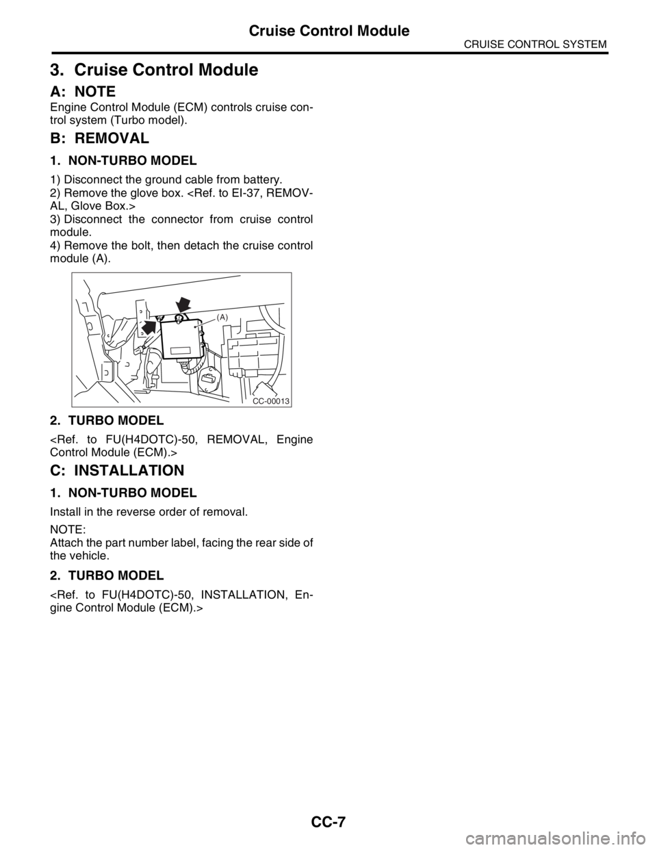
4) Remove the bolt, then detach the cruise control
module (A).
2. TURBO MODEL
Control Module (ECM).>
C: INSTALLATION
1. NON-TURBO MODEL
Install in the reverse order of removal.
NOTE:
Attach the part number label, facing the rear side of
the vehicle.
2. TURBO MODEL
gine Control Module (ECM).>
CC-00013
(A)
Page 560 of 2870
CC-8
CRUISE CONTROL SYSTEM
Cruise Control Main Switch
4. Cruise Control Main Switch
A: REMOVAL
1) Disconnect the ground cable from battery.
2) Remove the screws and clip from instrument
panel lower cover.
3) Remove the instrument panel lower cover.
4) Disconnect the connector from cruise control
main switch.
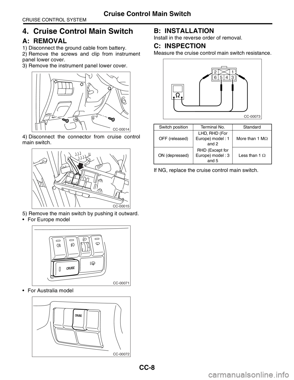
5) Remove the main switch by pushing it outward.
For Europe model
For Australia model
B: INSTALLATION
Install in the reverse order of removal.
C: INSPECTION
Measure the cruise control main switch resistance.
If NG, replace the cruise control main switch.
CC-00014
CC-00015
CC-00071
CC-00072
Switch position Terminal No. Standard
OFF (released)LHD, RHD (For
Europe) model : 1
and 2More than 1 MΩ
ON (depressed)RHD (Except for
Europe) model : 3
and 5Less than 1 Ω
CC-00073
1 2
64
53
Page 561 of 2870
CC-9
CRUISE CONTROL SYSTEM
Cruise Control Command Switch
5. Cruise Control Command
Switch
A: REMOVAL
WARNING:
Before servicing, be sure to read the notes in
the AB section for proper handling of the driv-
er’s airbag module.
General Description.>
1) Set the front wheels in straight ahead position.
2) Turn the ignition switch to OFF.
3) Disconnect the ground cable from battery and
wait for at least 20 seconds before starting work.
4) Using the TORX
® BIT T30 (Tamper resistant type),
loosen the two TORX® bolts which secure driver’s air-
bag module.
5) Disconnect the airbag module connector on
back of airbag module.
6) Remove the horn switch from steering wheel as
shown.7) Disconnect the horn and cruise control com-
mand switch connector, then remove the cruise
control command switch.
B: INSTALLATION
Install in the reverse order of removal.
C: INSPECTION
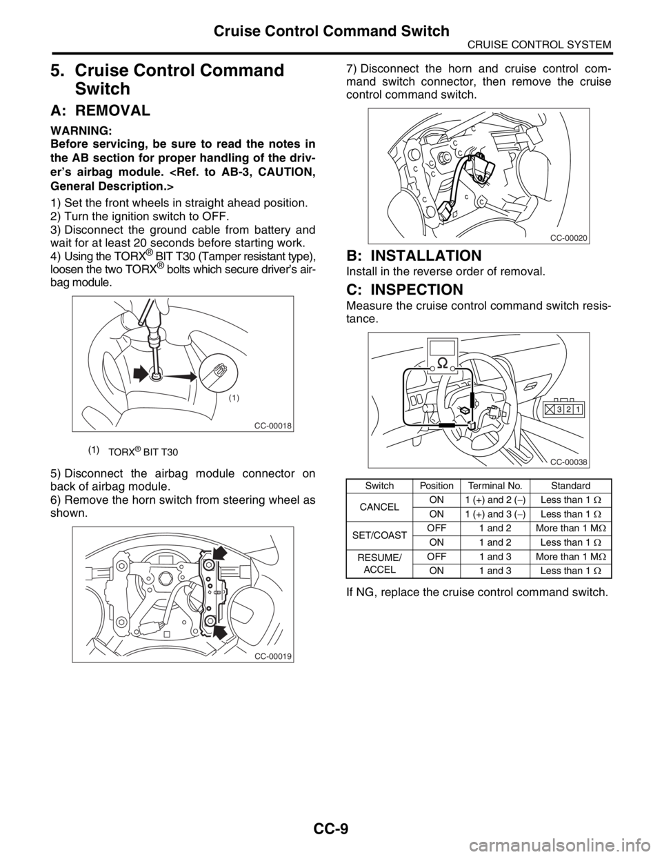
Measure the cruise control command switch resis-
tance.
If NG, replace the cruise control command switch.
(1)
TORX® BIT T30
CC-00018
(1)
CC-00019
Switch Position Terminal No. Standard
CANCELON 1 (+) and 2 (−) Less than 1 Ω
ON 1 (+) and 3 (−) Less than 1 Ω
SET/COASTOFF 1 and 2 More than 1 MΩ
ON 1 and 2 Less than 1 Ω
RESUME/
ACCELOFF 1 and 3 More than 1 MΩ
ON 1 and 3 Less than 1 Ω
CC-00020
CC-00038
1 2 3
Page 562 of 2870
CC-10
CRUISE CONTROL SYSTEM
Stop and Brake Switch
6. Stop and Brake Switch
A: REMOVAL
1) Disconnect the ground cable from battery.
2) Disconnect the connector from stop and brake
switch, and then remove the switch.
54, REMOVAL, Stop Light Switch.>
B: INSTALLATION
Install in the reverse order of removal.
C: INSPECTION
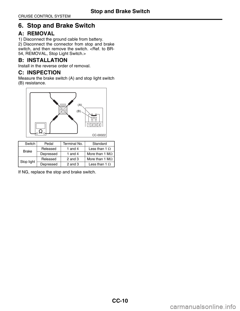
Measure the brake switch (A) and stop light switch
(B) resistance.
If NG, replace the stop and brake switch.
Switch Pedal Terminal No. Standard
BrakeReleased 1 and 4 Less than 1 Ω
Depressed 1 and 4 More than 1 MΩ
Stop lightReleased 2 and 3 More than 1 MΩ
Depressed 2 and 3 Less than 1 Ω
CC-00022
1234
(A)
(B)
3 2 14
Page 563 of 2870
CC-11
CRUISE CONTROL SYSTEM
Clutch Switch
7. Clutch Switch
A: REMOVAL
1) Disconnect the ground cable from battery.
2) Disconnect the connector from clutch switch,
and then remove the switch.
MOVAL, Clutch Pedal.>
B: INSTALLATION
Install in the reverse order of removal.
C: INSPECTION
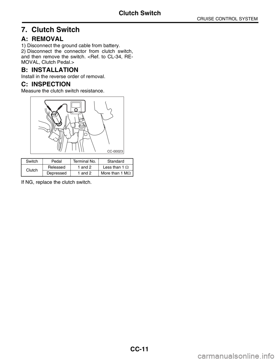
Measure the clutch switch resistance.
If NG, replace the clutch switch.
Switch Pedal Terminal No. Standard
ClutchReleased 1 and 2 Less than 1 Ω
Depressed 1 and 2 More than 1 MΩ
CC-00023
Page 564 of 2870
CC-12
CRUISE CONTROL SYSTEM
Inhibitor Switch (AT model)
8. Inhibitor Switch (AT model)
A: REMOVAL
1) Disconnect the ground cable from battery.
2) Disconnect the connector from inhibitor switch,
and then remove the switch.
MOVAL, Inhibitor Switch.>
B: INSTALLATION
Install in the reverse order of removal.
C: INSPECTION
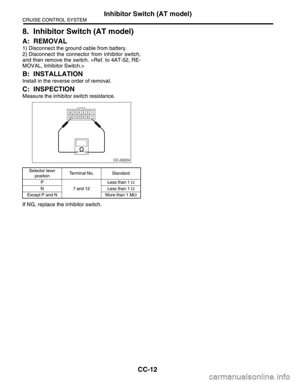
Measure the inhibitor switch resistance.
If NG, replace the inhibitor switch.
Selector lever
positionTerminal No. Standard
P
7 and 12Less than 1 Ω
N Less than 1 Ω
Except P and N More than 1 MΩ
CC-00024
123456789101112
Page 565 of 2870
CC-13
CRUISE CONTROL SYSTEM
Neutral Position Switch (MT model)
9. Neutral Position Switch (MT
model)
A: REMOVAL
1) Disconnect the ground cable from battery.
2) Disconnect the connector from neutral position
switch, and then remove the switch.
43, BACK-UP LIGHT AND NEUTRAL POSITION
SWITCH, REMOVAL, Switches and Harness.>
B: INSTALLATION
Install in the reverse order of removal.
C: INSPECTION
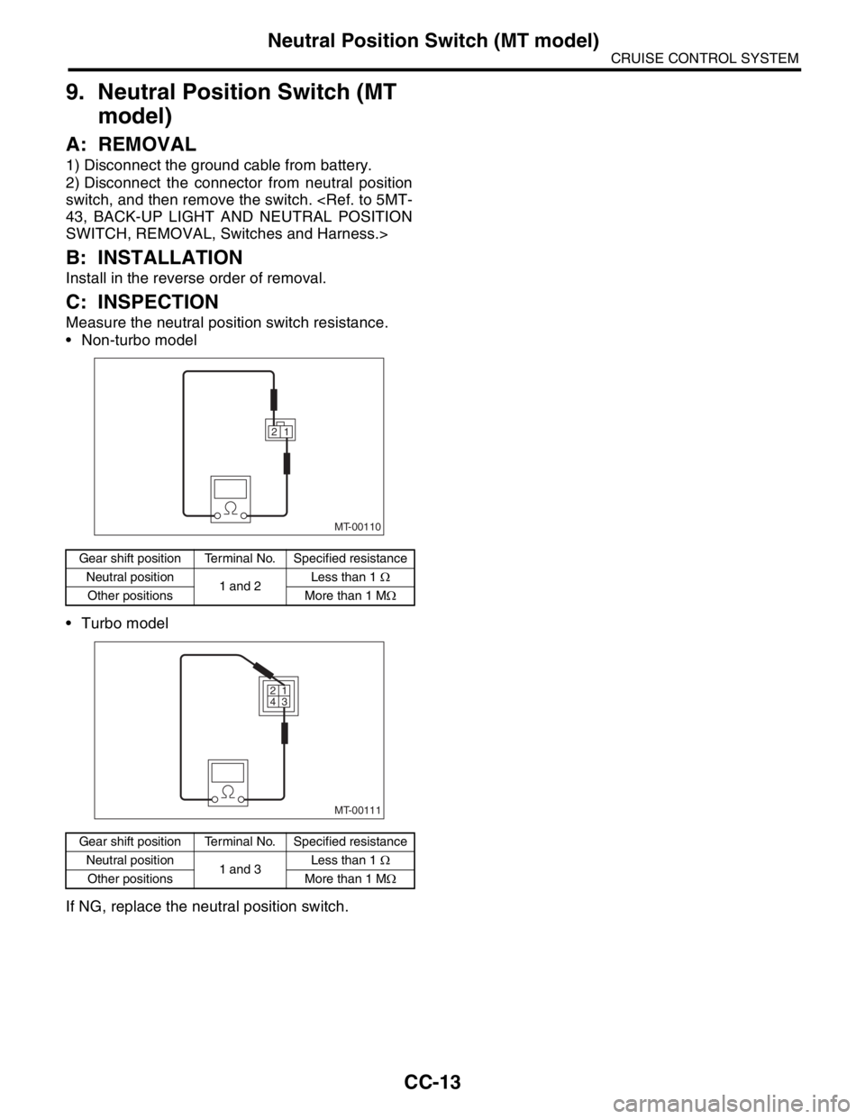
Measure the neutral position switch resistance.
Non-turbo model
Turbo model
If NG, replace the neutral position switch.
Gear shift position Terminal No. Specified resistance
Neutral position
1 and 2Less than 1 Ω
Other positions More than 1 MΩ
Gear shift position Terminal No. Specified resistance
Neutral position
1 and 3Less than 1 Ω
Other positions More than 1 MΩ
MT-00110
1 2
MT-00111
1 2
3 4