2004 SUBARU FORESTER check engine light
[x] Cancel search: check engine lightPage 896 of 2870
ME(H4SO)-27
MECHANICAL
Ignition Timing
4. Ignition Timing
A: INSPECTION
CAUTION:
After warming-up, engine becomes very hot. Be
careful not to burn yourself during measure-
ment.
1) Warm-up the engine.
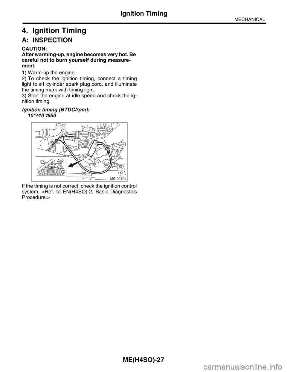
2) To check the ignition timing, connect a timing
light to #1 cylinder spark plug cord, and illuminate
the timing mark with timing light.
3) Start the engine at idle speed and check the ig-
nition timing.
Ignition timing [BTDC/rpm]:
10
°±10°/650
If the timing is not correct, check the ignition control
system.
ME-00194
Page 898 of 2870
ME(H4SO)-29
MECHANICAL
Engine Oil Pressure
6. Engine Oil Pressure
A: INSPECTION
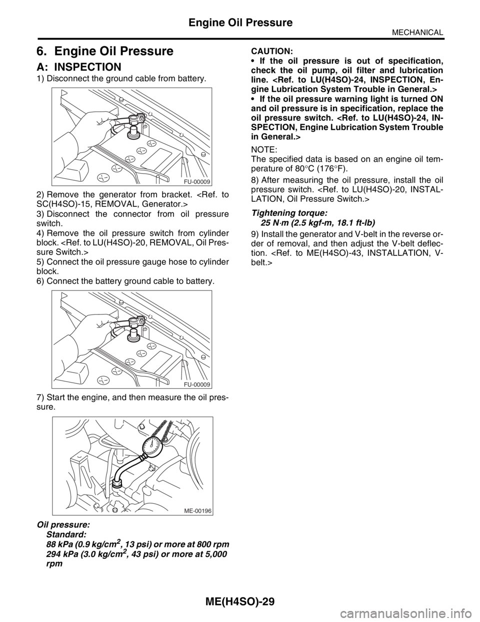
1) Disconnect the ground cable from battery.
2) Remove the generator from bracket.
3) Disconnect the connector from oil pressure
switch.
4) Remove the oil pressure switch from cylinder
block.
5) Connect the oil pressure gauge hose to cylinder
block.
6) Connect the battery ground cable to battery.
7) Start the engine, and then measure the oil pres-
sure.
Oil pressure:
Standard:
88 kPa (0.9 kg/cm
2, 13 psi) or more at 800 rpm
294 kPa (3.0 kg/cm2, 43 psi) or more at 5,000
rpmCAUTION:
If the oil pressure is out of specification,
check the oil pump, oil filter and lubrication
line.
If the oil pressure warning light is turned ON
and oil pressure is in specification, replace the
oil pressure switch.
in General.>
NOTE:
The specified data is based on an engine oil tem-
perature of 80°C (176°F).
8) After measuring the oil pressure, install the oil
pressure switch.
Tightening torque:
25 N
⋅m (2.5 kgf-m, 18.1 ft-lb)
9) Install the generator and V-belt in the reverse or-
der of removal, and then adjust the V-belt deflec-
tion.
FU-00009
FU-00009
ME-00196
Page 906 of 2870
ME(H4SO)-37
MECHANICAL
Engine Assembly
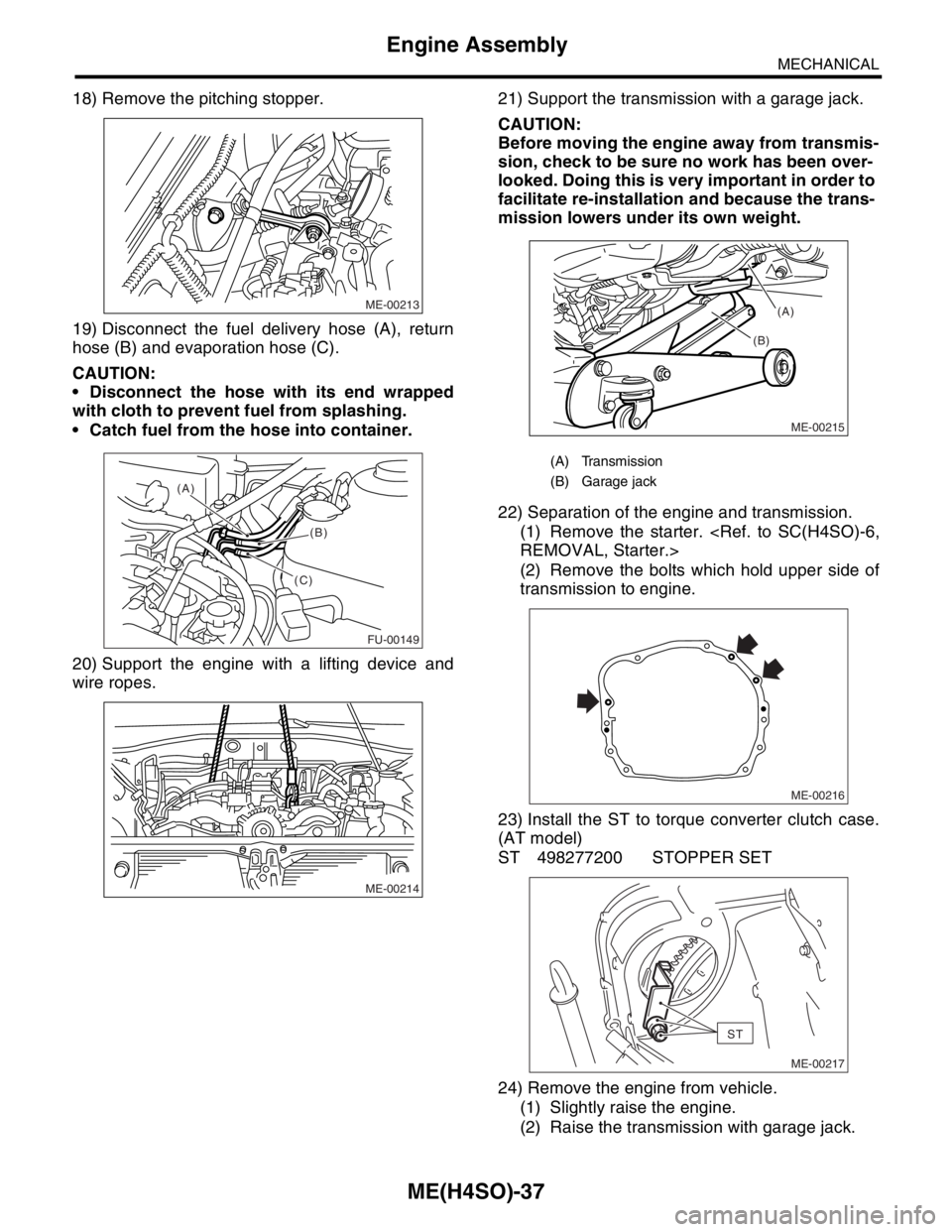
18) Remove the pitching stopper.
19) Disconnect the fuel delivery hose (A), return
hose (B) and evaporation hose (C).
CAUTION:
Disconnect the hose with its end wrapped
with cloth to prevent fuel from splashing.
Catch fuel from the hose into container.
20) Support the engine with a lifting device and
wire ropes.21) Support the transmission with a garage jack.
CAUTION:
Before moving the engine away from transmis-
sion, check to be sure no work has been over-
looked. Doing this is very important in order to
facilitate re-installation and because the trans-
mission lowers under its own weight.
22) Separation of the engine and transmission.
(1) Remove the starter.
(2) Remove the bolts which hold upper side of
transmission to engine.
23) Install the ST to torque converter clutch case.
(AT model)
ST 498277200 STOPPER SET
24) Remove the engine from vehicle.
(1) Slightly raise the engine.
(2) Raise the transmission with garage jack.
ME-00213
FU-00149
(A)
(B)
(C)
ME-00214
(A) Transmission
(B) Garage jack
ME-00215
(B)(A)
ME-00216
ST
ME-00217
Page 936 of 2870
ME(H4SO)-65
MECHANICAL
Cylinder Head
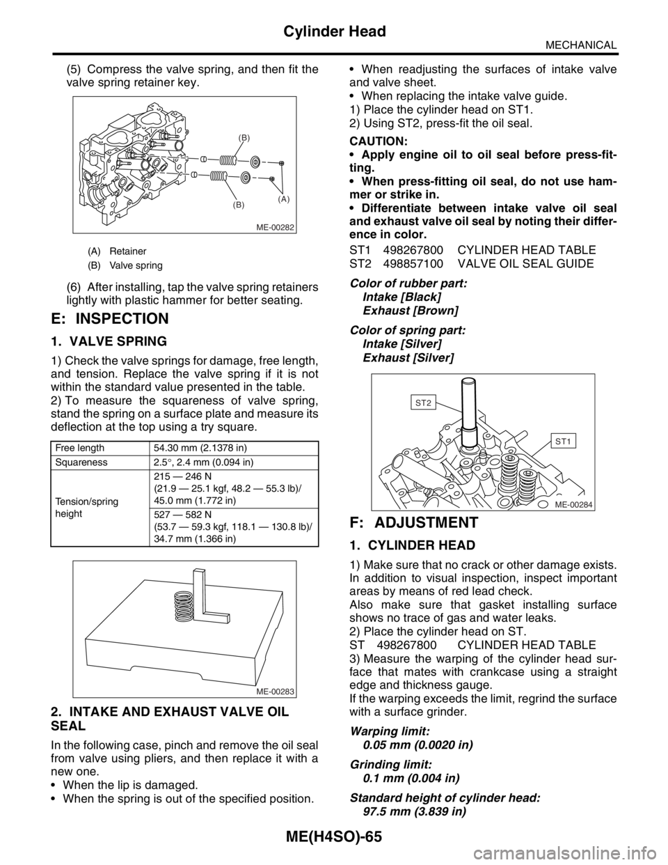
(5) Compress the valve spring, and then fit the
valve spring retainer key.
(6) After installing, tap the valve spring retainers
lightly with plastic hammer for better seating.
E: INSPECTION
1. VALVE SPRING
1) Check the valve springs for damage, free length,
and tension. Replace the valve spring if it is not
within the standard value presented in the table.
2) To measure the squareness of valve spring,
stand the spring on a surface plate and measure its
deflection at the top using a try square.
2. INTAKE AND EXHAUST VALVE OIL
SEAL
In the following case, pinch and remove the oil seal
from valve using pliers, and then replace it with a
new one.
When the lip is damaged.
When the spring is out of the specified position. When readjusting the surfaces of intake valve
and valve sheet.
When replacing the intake valve guide.
1) Place the cylinder head on ST1.
2) Using ST2, press-fit the oil seal.
CAUTION:
Apply engine oil to oil seal before press-fit-
ting.
When press-fitting oil seal, do not use ham-
mer or strike in.
Differentiate between intake valve oil seal
and exhaust valve oil seal by noting their differ-
ence in color.
ST1 498267800 CYLINDER HEAD TABLE
ST2 498857100 VALVE OIL SEAL GUIDE
Color of rubber part:
Intake [Black]
Exhaust [Brown]
Color of spring part:
Intake [Silver]
Exhaust [Silver]
F: ADJUSTMENT
1. CYLINDER HEAD
1) Make sure that no crack or other damage exists.
In addition to visual inspection, inspect important
areas by means of red lead check.
Also make sure that gasket installing surface
shows no trace of gas and water leaks.
2) Place the cylinder head on ST.
ST 498267800 CYLINDER HEAD TABLE
3) Measure the warping of the cylinder head sur-
face that mates with crankcase using a straight
edge and thickness gauge.
If the warping exceeds the limit, regrind the surface
with a surface grinder.
Warping limit:
0.05 mm (0.0020 in)
Grinding limit:
0.1 mm (0.004 in)
Standard height of cylinder head:
97.5 mm (3.839 in)
(A) Retainer
(B) Valve spring
Free length 54.30 mm (2.1378 in)
Squareness 2.5°, 2.4 mm (0.094 in)
Tension/spring
height215 — 246 N
(21.9 — 25.1 kgf, 48.2 — 55.3 lb)/
45.0 mm (1.772 in)
527 — 582 N
(53.7 — 59.3 kgf, 118.1 — 130.8 lb)/
34.7 mm (1.366 in)
ME-00282
(B)(B)
(A)
ME-00283
ME-00284
ST1
ST2
Page 938 of 2870
ME(H4SO)-67
MECHANICAL
Cylinder Head
(2) Insert the ST2 into valve guide and press it
down to remove valve guide.
ST1 498267800 CYLINDER HEAD TABLE
ST2 499767200 VALVE GUIDE REMOVER
(3) Turn the cylinder head upside down and
place ST as shown in the figure.
Intake side:
ST 499767700 VALVE GUIDE ADJUSTER
Exhaust side:
ST 499767800 VALVE GUIDE ADJUSTER
(4) Before installing new oversize valve guide,
make sure that neither scratches nor damages
exist on the inside surface of valve guide holes
in cylinder head.
(5) Put new valve guide, coated with sufficient
oil, in the cylinder, and then insert the ST1 into
valve guide. Press in until the valve guide upper
end is flush with the upper surface of ST2.ST1 499767200 VALVE GUIDE REMOVER
Intake side:
ST2 499767700 VALVE GUIDE ADJUSTER
Exhaust side:
ST2 499767800 VALVE GUIDE ADJUSTER
(6) Check the valve guide protrusion.
Valve guide protrusion: L
Intake
20.0 — 20.5 mm (0.787 — 0.807 in)
Exhaust
16.5 — 17.0 mm (0.650 — 0.669 in)
(7) Ream the inside of valve guide with ST.
Gently rotate the reamer clockwise while press-
ing it lightly into valve guide, and return it also ro-
tating clockwise. After reaming, clean the valve
guide to remove chips.
CAUTION:
Apply engine oil to the reamer when reaming.
If the inner surface of the valve guide is torn,
the edge of the reamer should be slightly
ground with an oil stone.
If the inner surface of the valve guide be-
comes lustrous and the reamer does not chips,
use a new reamer or remedy the reamer.
(A) Valve guide
ME-00290
ST2
ST1
(A)
ME-00291
ST
(A) Valve guide
ST2
ME-00292
ST1
ME-00293(A)L
Page 1037 of 2870

LU(H4SO)-9
LUBRICATION
Oil Pressure System
B: INSPECTION
Step Check Yes No
1 CHECK COMBINATION METER.
1) Turn the ignition switch to ON. (engine
OFF)
2) Check other warning lights.Does the warning lights illumi-
nate?Go to step 2.Repair or replace
the combination
meter.
Combination
Meter System.>
2 CHECK HARNESS CONNECTOR BETWEEN
COMBINATION METER AND OIL PRES-
SURE SWITCH.
1) Turn the ignition switch to OFF.
2) Disconnect the connector from oil pressure
switch.
3) Turn the ignition switch to ON.
4) Measure the voltage of harness between
the combination meter connector and chassis
ground.
Connector & terminal
(E11) No. 1 (+) — Chassis ground (
−):Is the voltage more than 10 V? Replace the oil
pressure switch.Go to step 3.
3 CHECK COMBINATION METER.
1) Turn the ignition switch to OFF.
2) Remove the combination meter.
3) Measure the resistance of combination
meter.
Te r m i n a l
No. B9 — No. A3:Is the resistance less than 10
Ω?Replace the har-
ness connector
between combina-
tion meter and oil
pressure switch.Repair or replace
the combination
meter and the oil
pressure switch
warning light bulb.
Page 1052 of 2870

LU(H4SO)-24
LUBRICATION
Engine Lubrication System Trouble in General
9. Engine Lubrication System Trouble in General
A: INSPECTION
Before performing diagnostics, make sure that the engine oil level is correct and no oil leakage exists.
Trouble Possible cause Corrective action
1. Warning light remains
on.1) Oil pressure switch
failureCracked diaphragm or oil leakage within switch Replace.
Broken spring or seized contacts Replace.
2) Low oil pressureClogged oil filter Replace.
Malfunction of oil by-pass valve of oil filter Clean or replace.
Malfunction of oil relief valve of oil pump Clean or replace.
Clogged oil passage Clean.
Excessive tip clearance and side clearance of oil
pump rotor and gearReplace.
Clogged oil strainer or broken pipe Clean or replace.
3) No oil pressureInsufficient engine oil Replenish.
Broken pipe of oil strainer Replace.
Stuck oil pump rotor Replace.
2. Warning light does
not go on.1) Malfunction of combination meter Replace.
2) Poor contact of switch contact points Replace.
3) Disconnection of wiring Repair.
3. Warning light flickers
momentarily.1) Poor contact at terminals Repair.
2) Defective wiring harness Repair.
3) Low oil pressureCheck for the same
possible causes as
listed in 1. — 2).
Page 1099 of 2870

ENGINE (DIAGNOSTIC)
EN(H4SO)
Page
1. Basic Diagnostics Procedure ......................................................................2
2. Check List for Interview ...............................................................................4
3. General Description ....................................................................................6
4. Electrical Component Location ...................................................................9
5. Engine Control Module (ECM) I/O Signal .................................................21
6. Engine Condition Data ..............................................................................24
7. Transmission Control Module (TCM) I/O Signal .......................................25
8. Data Link Connector .................................................................................26
9. OBD-II General Scan Tool ........................................................................27
10. Subaru Select Monitor...............................................................................29
11. Read Diagnostic Trouble Code (DTC) ......................................................36
12. Inspection Mode ........................................................................................37
13. Drive Cycle ................................................................................................42
14. Clear Memory Mode..................................................................................44
15. Compulsory Valve Operation Check Mode ...............................................45
16. Malfunction Indicator Light ........................................................................47
17. Diagnostics for Engine Starting Failure .....................................................57
18. List of Diagnostic Trouble Code (DTC) .....................................................72
19. Diagnostic Procedure with Diagnostic Trouble Code (DTC) .....................78
20. General Diagnostic Table........................................................................255