2004 SUBARU FORESTER check engine light
[x] Cancel search: check engine lightPage 645 of 2870
IM-3
IMMOBILIZER (DIAGNOSTIC)
General Description
2. General Description
A: CAUTION
CAUTION:
The airbag system wiring harnesses rout-
ed near the immobilizer control module. All
airbag system wiring harness and connec-
tors are colored yellow. Do not use electrical
test equipment on these circuits.
Be careful not to damage the airbag system
wiring harness when servicing the immobilizer
control module.
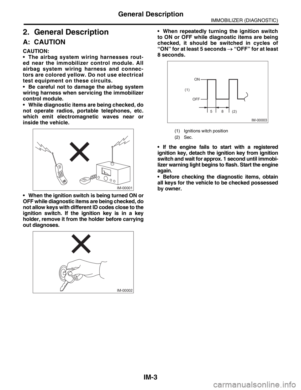
While diagnostic items are being checked, do
not operate radios, portable telephones, etc.
which emit electromagnetic waves near or
inside the vehicle.
When the ignition switch is being turned ON or
OFF while diagnostic items are being checked, do
not allow keys with different ID codes close to the
ignition switch. If the ignition key is in a key
holder, remove it from the holder before carrying
out diagnoses. When repeatedly turning the ignition switch
to ON or OFF while diagnostic items are being
checked, it should be switched in cycles of
“ON” for at least 5 seconds → “OFF” for at least
8 seconds.
If the engine fails to start with a registered
ignition key, detach the ignition key from ignition
switch and wait for approx. 1 second until immobi-
lizer warning light begins to flash. Start the engine
again.
Before checking the diagnostic items, obtain
all keys for the vehicle to be checked possessed
by owner.
IM-00001
IM-00002
(1) Ignitions witch position
(2) Sec.
IM-00003
ON
OFF
58
(2) (1)
Page 653 of 2870

IM-11
IMMOBILIZER (DIAGNOSTIC)
Diagnostics Chart for Immobilizer Warning Light
Step Check Yes No
1 CHECK IMMOBILIZER WARNING LIGHT.
1) Turn the ignition switch to OFF.
2) Disconnect the harness connector from
IMM ECM.
3) Connect a resistor (750 Ω) between IMM
ECM harness connector terminal No. 9 and
chassis ground.Does the immobilizer warning
light illuminate?Go to step 2.Go to step 5.
2 CHECK IMM ECM GROUND CIRCUIT.
Measure the resistance between IMM ECM
harness connector terminal and chassis
ground.
Connector & terminal
(B141) No. 2, No. 3 — Chassis ground:Is the resistance less than 10
Ω?Go to step 3.Repair the open
circuit of IMMECM
ground circuit.
3 CHECK IMM ECM IGNITION CIRCUIT.
1) Turn the ignition switch to ON. (engine
OFF.)
2) Measure the voltage between IMM ECM
harness connector terminal and chassis
ground.
Connector & terminal
(B141) No. 12 (+) — Chassis ground(
−):Is the voltage more than 10 V? Go to step 4.Check the harness
for open or short
between IMM
ECM and ignition
switch.
4 CHECK IMM ECM POWER SUPPLY CIR-
CUIT.
1) Turn the ignition switch to OFF.
2) Measure the voltage between IMM ECM
harness connector terminal and chassis
ground.
Connector & terminal
(B141) No. 10, No. 11 (+) — Chassis
ground(
−):Is the voltage more than 10 V? Replace the IMM
ECM
Control Module.>
and then replace
all ignition keys
(including the tran-
sponder). Then
perform teaching
operation. Refer to
teaching opera-
tion manual (Pub.
No. S0820GZ).Check the harness
for open or short
between IMM
ECM and fuse.
5 CHECK COMBINATION METER CIRCUIT.
1) Remove the combination meter.
2) Measure the voltage between combination
meter harness connector terminal and chassis
ground.
Connector & terminal
(i10) No. 8 (+) — Chassis ground (
−):Is the voltage more than 10 V? Go to step 6.Check the harness
for open or short
between combina-
tion meter and
fuse.
6 CHECK COMBINATION METER CIRCUIT.
Measure the resistance between IMM ECM
harness connector terminal and combination
meter harness connector terminal.
Connector & terminal
LHD model
(B141) No. 9 — (i12) No. 4:
RHD model
(B141) No. 9 — (i11) No. 5:Is the resistance less than 10
Ω?Faulty LED.
Replace the com-
bination meter
printed circuit.
Combination
Meter Assembly.>Repair the har-
ness or connector.
Page 726 of 2870

PI-3
PRE-DELIVERY INSPECTION
Pre-delivery Inspection
B: PDI PROCEDURE
Follow the procedures shown in the table below.
Static Checks Just After Vehicle Receipt
Step Check point
1. Appearance check (1) If the vehicle is covered with protective coating, visually check the vehicle
body for damage and dents. If the protective coating has been removed,
visually check the body paints for small areas of damage or stains.
(2) Visually check the glass and light lenses for any damage and cracks or
excessive gaps to the body sheet metal.
(3) Visually check the plated parts for any damage.
2. Tire check (1) Check the tires for damage, abnormal conditions, and dents on the
wheels.
(2) Check the tire air pressure.
3. Fuse installation If the vehicle is about to be delivered to the customer, attach a room light
fuse.
4. Connection of air conditioner harness If the vehicle is about to be delivered to the customer, connect the air condi-
tioner harness.
5. Check the doors for lock/unlock and open/close
operations.(1) Using the key, check if the door can be locked and unlocked normally.
(2) Open and close all doors to see that there are no abnormal conditions.
6. Operation check of double lock Check that the double lock operates normally.
7. Operation check of the child safety lock system. Check the child safety lock system operates normally.
8. Check the rear gate for lock/unlock and open/
close operations.(1) Check if the rear gate can be unlocked normally from the emergency
door.
(2) Open and close the rear gate to see that there are no abnormal condi-
tions.
(3) Operate the power door locking switch to check that the rear gate is
locked and unlocked normally.
9. Operation check of fuel lid opener lock release
leverOperate the fuel lid opener to check that the fuel lid is unlocked normally.
10. Accessory check Check that the following accessories are provided:
Owner’s manual
Warranty booklet
Service booklet
Spare key
Jack
Tool set
Spare tire
11. Operation check of hood lock release system Operate the hood lock release lever to check that the hood opens normally.
12. Battery Check the battery for any abnormal conditions such as rust and trace of bat-
tery fluid leaks.
13. Brake fluid Check the fluid amount.
14. Engine oil Check the oil amount.
15. Transmission fluid (1) Check the fluid amount.
(2) For AT, check the front differential oil.
16. AT front differential oil Check the AT front differential oil amount.
17. Coolant Check the coolant amount.
18. Clutch fluid Check the clutch fluid amount.
19. Window washer fluid Check the window washer fluid amount.
20. Hood latch check Check that the hood is closed and latched securely.
21. Keyless entry system Check that the keyless entry system operates normally.
22. Security system Check that the security system operates normally.
23. Seat (1) Check the seat surfaces for smears or dirt.
(2) Check the seat installation conditions and functionality.
24. Seat belt Check the seat belt installation conditions and functionality.
25. Wheel alignment Check that the wheel alignments are properly adjusted.
Page 727 of 2870

PI-4
PRE-DELIVERY INSPECTION
Pre-delivery Inspection
Checks with the Engine Running
Dynamic Test with the Vehicle Running
Checks after Dynamic Test
Step Check point
26. Test mode connectors Test mode connectors
27. Starting condition Start the engine and check that the engine starts smoothly.
28. Exhaust system Check that the exhaust noise is normal and no leaks are found.
29. Indicator light Check that all the indicator lights operate normally.
30. Clock Check that the clock operates normally.
31. Radio Check that the radio system operates normally.
32. Front accessory power supply socket Check that the front accessory power supply socket operates normally.
33. Lighting system Check that the lighting systems operate normally.
34. Window washer Check that the window washer system operates normally.
35. Wiper Check that the wiper system operates normally.
36. Power window operation check Check the power window for correct operations.
Step Check point
37. Brake test Check that the foot brake operates normally.
38. Parking brake Check that the parking brake operates normally.
39. AT shift control Check the AT shift patterns are correct.
40. Heater & ventilation Check that the heater & ventilation system operates normally.
41. Air conditioner Check that the air conditioner operates normally.
42. Speed control Check that the speed control operates normally.
Step Check point
43. ATF level Check that the ATF level is normal.
44. Power steering fluid level Check that the power steering fluid level is normal.
45. Fluid leak check Check for fluid/oil leaks.
46. Water leak check Spray the vehicle with water and check for water leaks.
47. Appearance check 2 (1) Remove the protective coating (wrap guard).(if any)
(2) Check the body paints for damage and smears.
(3) Check the plated parts for damage and rust.
Page 733 of 2870
PI-10
PRE-DELIVERY INSPECTION
Pre-delivery Inspection
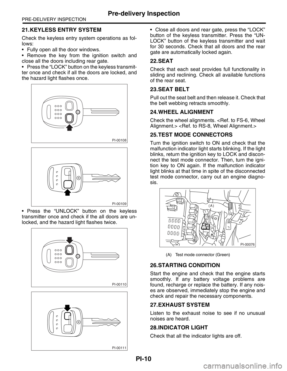
21.KEYLESS ENTRY SYSTEM
Check the keyless entry system operations as fol-
lows:
Fully open all the door windows.
Remove the key from the ignition switch and
close all the doors including rear gate.
Press the “LOCK” button on the keyless transmit-
ter once and check if all the doors are locked, and
the hazard light flashes once.
Press the “UNLOCK” button on the keyless
transmitter once and check if the all doors are un-
locked, and the hazard light flashes twice. Close all doors and rear gate, press the “LOCK”
button of the keyless transmitter. Press the “UN-
LOCK” button of the keyless transmitter and wait
for 30 seconds. Check that all doors and the rear
gate are automatically locked again.
22.SEAT
Check that each seat provides full functionality in
sliding and reclining. Check all available functions
of the rear seat.
23.SEAT BELT
Pull out the seat belt and then release it. Check that
the belt webbing retracts smoothly.
24.WHEEL ALIGNMENT
Check the wheel alignments.
25.TEST MODE CONNECTORS
Turn the ignition switch to ON and check that the
malfunction indicator light starts blinking. If the light
blinks, return the ignition key to LOCK and discon-
nect the test mode connector. Then, turn the igni-
tion key to ON again. If the malfunction indicator
light blinks at that time in spite of the disconnected
test mode connector, carry out an engine diagno-
sis.
26.STARTING CONDITION
Start the engine and check that the engine starts
smoothly. If any battery voltage problems are
found, recharge or replace the battery. If any nois-
es are observed, immediately stop the engine and
check and repair the necessary components.
27.EXHAUST SYSTEM
Listen to the exhaust noise to see if no unusual
noises are heard.
28.INDICATOR LIGHT
Check that all the indicator lights are off.
PI-00108
PI-00109
PI-00110
PI-00111
(A) Test mode connector (Green)
PI-00076
(A)
Page 767 of 2870
PM-30
PERIODIC MAINTENANCE SERVICE
Brake Line
18.Brake Line
A: INSPECTION
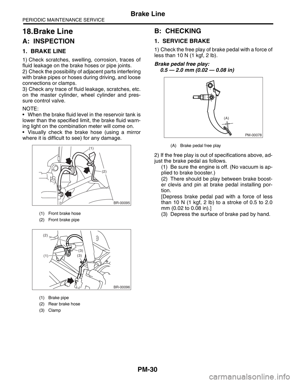
1. BRAKE LINE
1) Check scratches, swelling, corrosion, traces of
fluid leakage on the brake hoses or pipe joints.
2) Check the possibility of adjacent parts interfering
with brake pipes or hoses during driving, and loose
connections or clamps.
3) Check any trace of fluid leakage, scratches, etc.
on the master cylinder, wheel cylinder and pres-
sure control valve.
NOTE:
When the brake fluid level in the reservoir tank is
lower than the specified limit, the brake fluid warn-
ing light on the combination meter will come on.
Visually check the brake hose (using a mirror
where it is difficult to see) for any damage.
B: CHECKING
1. SERVICE BRAKE
1) Check the free play of brake pedal with a force of
less than 10 N (1 kgf, 2 lb).
Brake pedal free play:
0.5 — 2.0 mm (0.02 — 0.08 in)
2) If the free play is out of specifications above, ad-
just the brake pedal as follows.
(1) Be sure the engine is off. (No vacuum is ap-
plied to brake booster.)
(2) There should be play between brake boost-
er clevis and pin at brake pedal installing por-
tion.
[Depress brake pedal pad with a force of less
than 10 N (1 kgf, 2 lb) to a stroke of 0.5 to 2.0
mm (0.02 to 0.08 in).]
(3) Depress the surface of brake pad by hand.
(1) Front brake hose
(2) Front brake pipe
(1) Brake pipe
(2) Rear brake hose
(3) Clamp
BR-00095
(1)
(2)
(1)
(3)
(3) (2)
BR-00096
(A) Brake pedal free play
PM-00078
(A)
Page 768 of 2870
PM-31
PERIODIC MAINTENANCE SERVICE
Brake Line
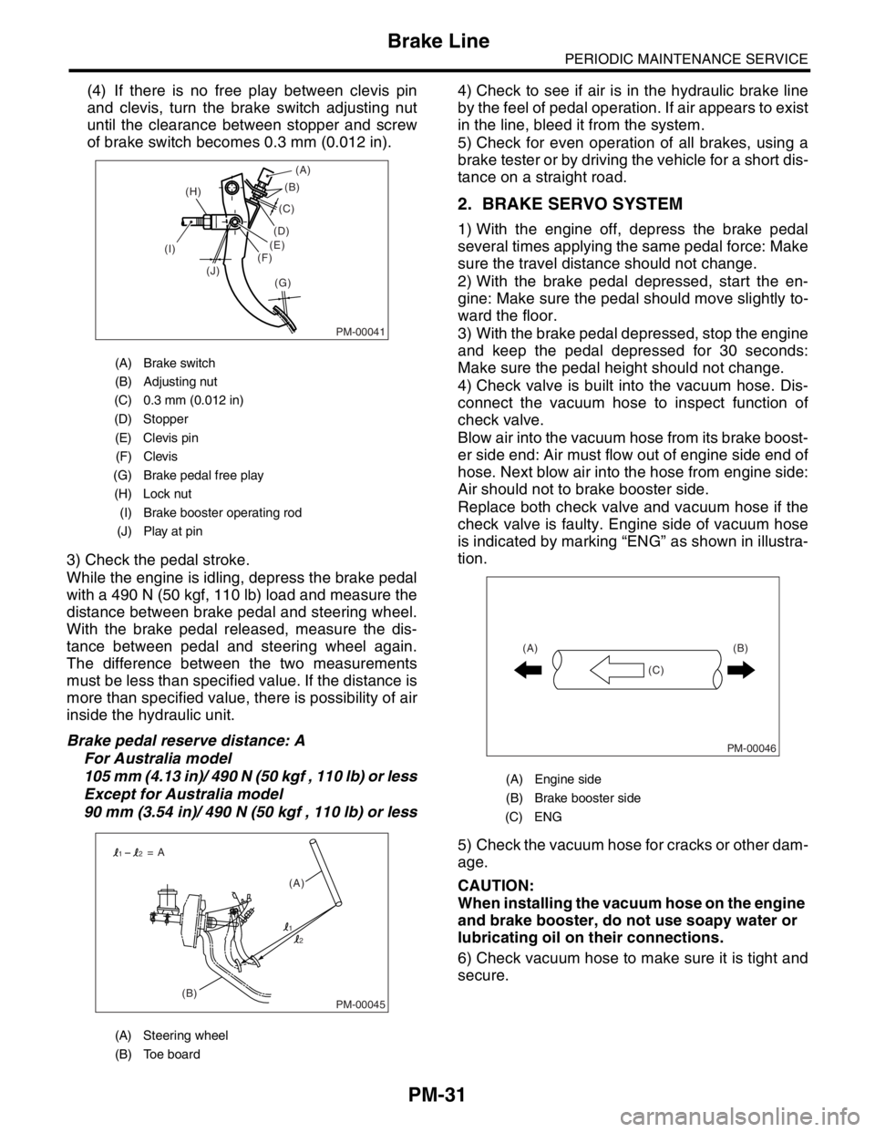
(4) If there is no free play between clevis pin
and clevis, turn the brake switch adjusting nut
until the clearance between stopper and screw
of brake switch becomes 0.3 mm (0.012 in).
3) Check the pedal stroke.
While the engine is idling, depress the brake pedal
with a 490 N (50 kgf, 110 lb) load and measure the
distance between brake pedal and steering wheel.
With the brake pedal released, measure the dis-
tance between pedal and steering wheel again.
The difference between the two measurements
must be less than specified value. If the distance is
more than specified value, there is possibility of air
inside the hydraulic unit.
Brake pedal reserve distance: A
For Australia model
105 mm (4.13 in)/ 490 N (50 kgf , 110 lb) or less
Except for Australia model
90 mm (3.54 in)/ 490 N (50 kgf , 110 lb) or less4) Check to see if air is in the hydraulic brake line
by the feel of pedal operation. If air appears to exist
in the line, bleed it from the system.
5) Check for even operation of all brakes, using a
brake tester or by driving the vehicle for a short dis-
tance on a straight road.
2. BRAKE SERVO SYSTEM
1) With the engine off, depress the brake pedal
several times applying the same pedal force: Make
sure the travel distance should not change.
2) With the brake pedal depressed, start the en-
gine: Make sure the pedal should move slightly to-
ward the floor.
3) With the brake pedal depressed, stop the engine
and keep the pedal depressed for 30 seconds:
Make sure the pedal height should not change.
4) Check valve is built into the vacuum hose. Dis-
connect the vacuum hose to inspect function of
check valve.
Blow air into the vacuum hose from its brake boost-
er side end: Air must flow out of engine side end of
hose. Next blow air into the hose from engine side:
Air should not to brake booster side.
Replace both check valve and vacuum hose if the
check valve is faulty. Engine side of vacuum hose
is indicated by marking “ENG” as shown in illustra-
tion.
5) Check the vacuum hose for cracks or other dam-
age.
CAUTION:
When installing the vacuum hose on the engine
and brake booster, do not use soapy water or
lubricating oil on their connections.
6) Check vacuum hose to make sure it is tight and
secure.
(A) Brake switch
(B) Adjusting nut
(C) 0.3 mm (0.012 in)
(D) Stopper
(E) Clevis pin
(F) Clevis
(G) Brake pedal free play
(H) Lock nut
(I) Brake booster operating rod
(J) Play at pin
(A) Steering wheel
(B) Toe board
PM-00041
(B)
(G) (H)
(I)
(J)(C)
(D)
(E)
(F)(A)
PM-00045(B)(A) = A
1
12
2
(A) Engine side
(B) Brake booster side
(C) ENG
PM-00046
(B)
(C) (A)
Page 895 of 2870
ME(H4SO)-26
MECHANICAL
Idle Speed
3. Idle Speed
A: INSPECTION
1) Before checking idle speed, check the following:
(1) Ensure the air cleaner element is free from
clogging, ignition timing is correct, spark plugs
are in good condition, and the hoses are con-
nected properly.
(2) Ensure the malfunction indicator light does
not illuminate.
2) Warm-up the engine.
3) Stop the engine, and then turn the ignition switch
to OFF.
4) When using the Subaru Select Monitor, refer to
the following.
tion.>
(1) Insert the cartridge to Subaru Select Moni-
tor.
(2) Connect the Subaru Select Monitor to data
link connector.
(3) Turn the ignition switch to ON, and Subaru
Select Monitor switch to ON.
(4) Select the {Each System Check} in Main
Menu.
(5) Select the {Engine Control System} in Se-
lection Menu.
(6) Select the {Current Data Display & Save} in
Engine Control System Diagnosis.
(7) Select the {Data Display} in Data Display
Menu.
(8) Start the engine, and then read the engine
idle speed.
5) When using the tachometer (Secondary pick-up
type).
(1) Attach the pick-up clip to No. 1 cylinder
spark plug cord.(2) Start the engine, and then read the engine
idle speed.
NOTE:
When using the OBD-II general scan tool, care-
fully read its operation manual.
This ignition system provides simultaneous igni-
tion for #1 and #2 plugs. It must be noted that some
tachometers may register twice that of actual en-
gine speed.
6) Check the idle speed when unloaded. (With
headlights, heater fan, rear defroster, radiator fan,
air conditioning, etc. OFF)
Idle speed [No load and gears in “N” or “P”
range]:
650
±100 rpm
7) Check the idle speed when loaded. (Turn the air
conditioning switch to “ON” and operate the com-
pressor for at least 1 minute before measurement.)
Idle speed [A/C “ON”, no load and gears in “N”
or “P” range]:
850
±100 rpm
NOTE:
Idle speed can not be adjusted manually, because
the idle speed is automatically adjusted.
If the specified idle speed can not be maintained,
refer to General On-board Diagnosis Table under
“Engine Control System”.
ME-00325
ME-00193