Page 649 of 2870
IM-7
IMMOBILIZER (DIAGNOSTIC)
Subaru Select Monitor
5. Subaru Select Monitor
A: OPERATION
1. HOW TO USE SUBARU SELECT MONI-
TOR
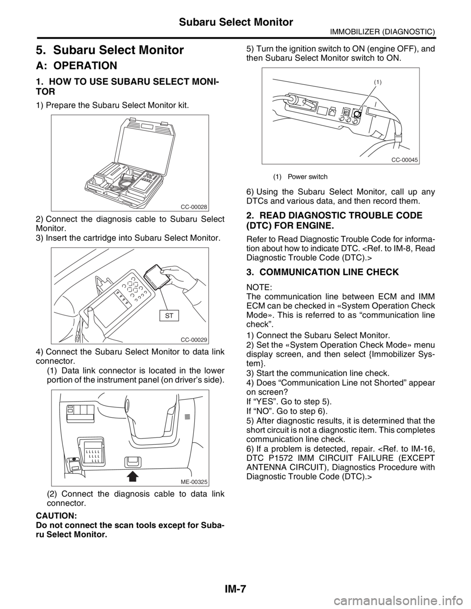
1) Prepare the Subaru Select Monitor kit.
2) Connect the diagnosis cable to Subaru Select
Monitor.
3) Insert the cartridge into Subaru Select Monitor.
4) Connect the Subaru Select Monitor to data link
connector.
(1) Data link connector is located in the lower
portion of the instrument panel (on driver’s side).
(2) Connect the diagnosis cable to data link
connector.
CAUTION:
Do not connect the scan tools except for Suba-
ru Select Monitor.5) Turn the ignition switch to ON (engine OFF), and
then Subaru Select Monitor switch to ON.
6) Using the Subaru Select Monitor, call up any
DTCs and various data, and then record them.
2. READ DIAGNOSTIC TROUBLE CODE
(DTC) FOR ENGINE.
Refer to Read Diagnostic Trouble Code for informa-
tion about how to indicate DTC.
Diagnostic Trouble Code (DTC).>
3. COMMUNICATION LINE CHECK
NOTE:
The communication line between ECM and IMM
ECM can be checked in «System Operation Check
Mode». This is referred to as “communication line
check”.
1) Connect the Subaru Select Monitor.
2) Set the «System Operation Check Mode» menu
display screen, and then select {Immobilizer Sys-
tem}.
3) Start the communication line check.
4) Does “Communication Line not Shorted” appear
on screen?
If “YES”. Go to step 5).
If “NO”. Go to step 6).
5) After diagnostic results, it is determined that the
short circuit is not a diagnostic item. This completes
communication line check.
6) If a problem is detected, repair.
DTC P1572 IMM CIRCUIT FAILURE (EXCEPT
ANTENNA CIRCUIT), Diagnostics Procedure with
Diagnostic Trouble Code (DTC).>
CC-00028
CC-00029
ME-00325
(1) Power switch
CC-00045
(1)
Page 651 of 2870
IM-9
IMMOBILIZER (DIAGNOSTIC)
Clear Memory Mode
7. Clear Memory Mode
A: OPERATION
1) On the «Main Menu» display screen, select the
{Each System Check}, and then press the [YES] key.
2) On the «System Selection Menu» display screen,
select the {Engine Control System}, and then press the
[YES] key.
3) Press the [YES] key after displayed information
of engine type.
4) On the «Engine Diagnosis» display screen, se-
lect the {Clear Memory}, and then press the [YES]
key.
5) When the `Done’ is shown on the display screen,
turn the Subaru Select Monitor and ignition switch
to OFF.
NOTE:
After the memory has been cleared, the ISC must be
initialized.To do this, turn the ignition switch to ON po-
sition. Wait 3 seconds before starting the engine.
For detailed operation procedure, refer to the SUB-
ARUSELECT MONITOR OPERATION MANUAL.
Page 712 of 2870
ID-3
IDENTIFICATION
Identification
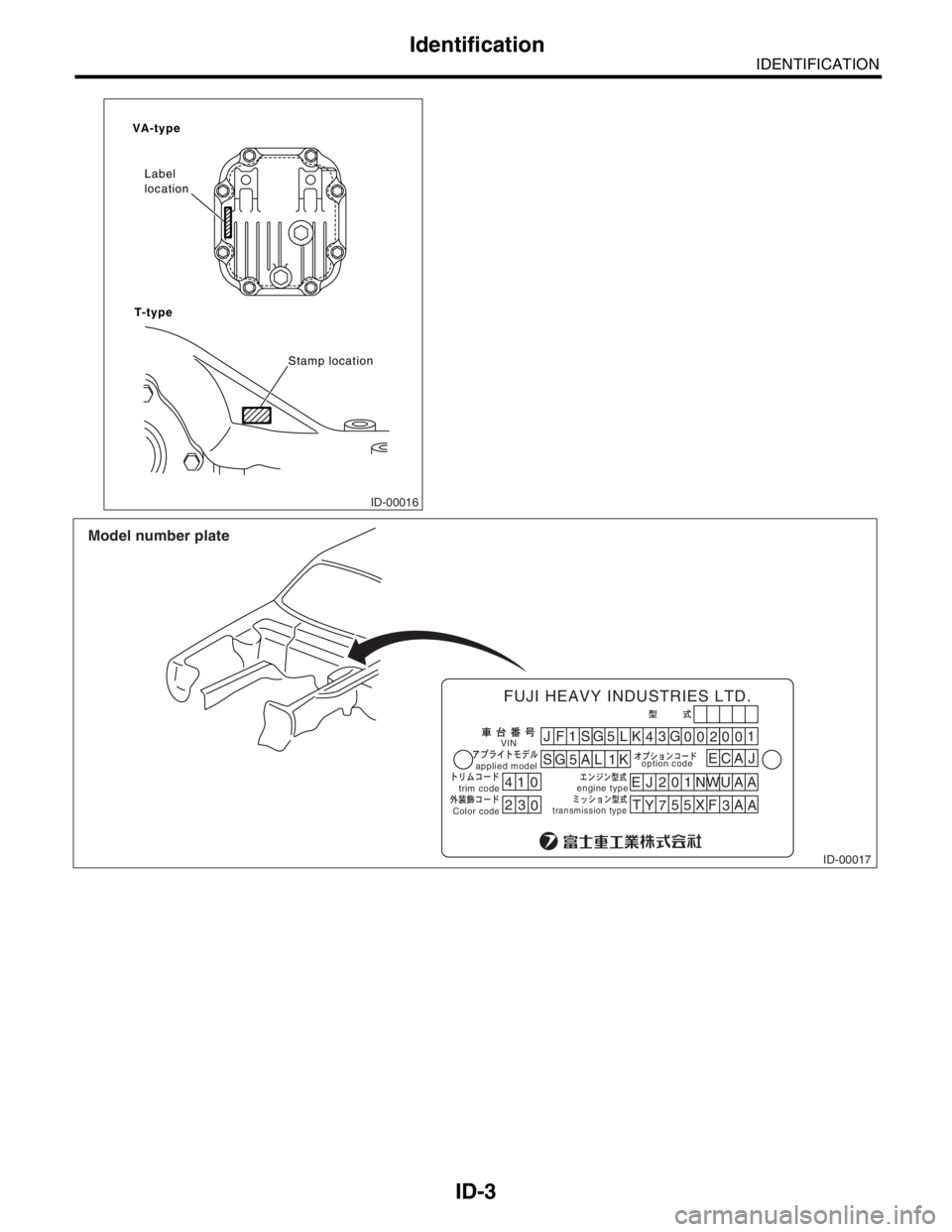
ID-00016
VA-type
T-typeLabel
location
Stamp location
ID-00017
41JF1
SG
5L
SG 5 A L 1KK
43
EJ 201NWUAA
T
Y755
XF
3A
A G
00200
EC1
0
23
0
applied modeloption code
trim codeVIN
engine type
transmission typeColor code
FUJI HEAVY INDUSTRIES LTD.
Model number plate
AJ
Page 717 of 2870
RM-2
RECOMMENDED MATERIAL
Recommended Materials
1. Recommended Materials
A: RECOMMENDED MATERIALS
1. GENERAL
To insure the best performance, always use the
specified oil, gasoline, adhesive, sealant, etc. or a
substitute of equivalent quality.
2. FUEL
Always use a gasoline of the same or higher octane
value than specified in the owner’s manual. Ignor-
ing the specifications below will result in damage or
poor operation of the engine and fuel injection sys-
tem. Use the specified gasoline to correct perfor-
mance.
Unleaded gasoline
Use unleaded gasoline and not leaded gasoline on
vehicles with catalytic converter installed to reduce
air pollution. Using leaded gasoline will damage the
catalytic converter.
*For Australia model.
Leaded gasoline
On vehicles without catalytic converter, use leaded
gasoline with an octane value of 90 RON or higher.
Model Petrol RON
Non-turbo UnleadedMore than 95 RON
More than 90 RON
*
Turbo Unleaded More than 98 RON
Page 719 of 2870
RM-4
RECOMMENDED MATERIAL
Recommended Materials
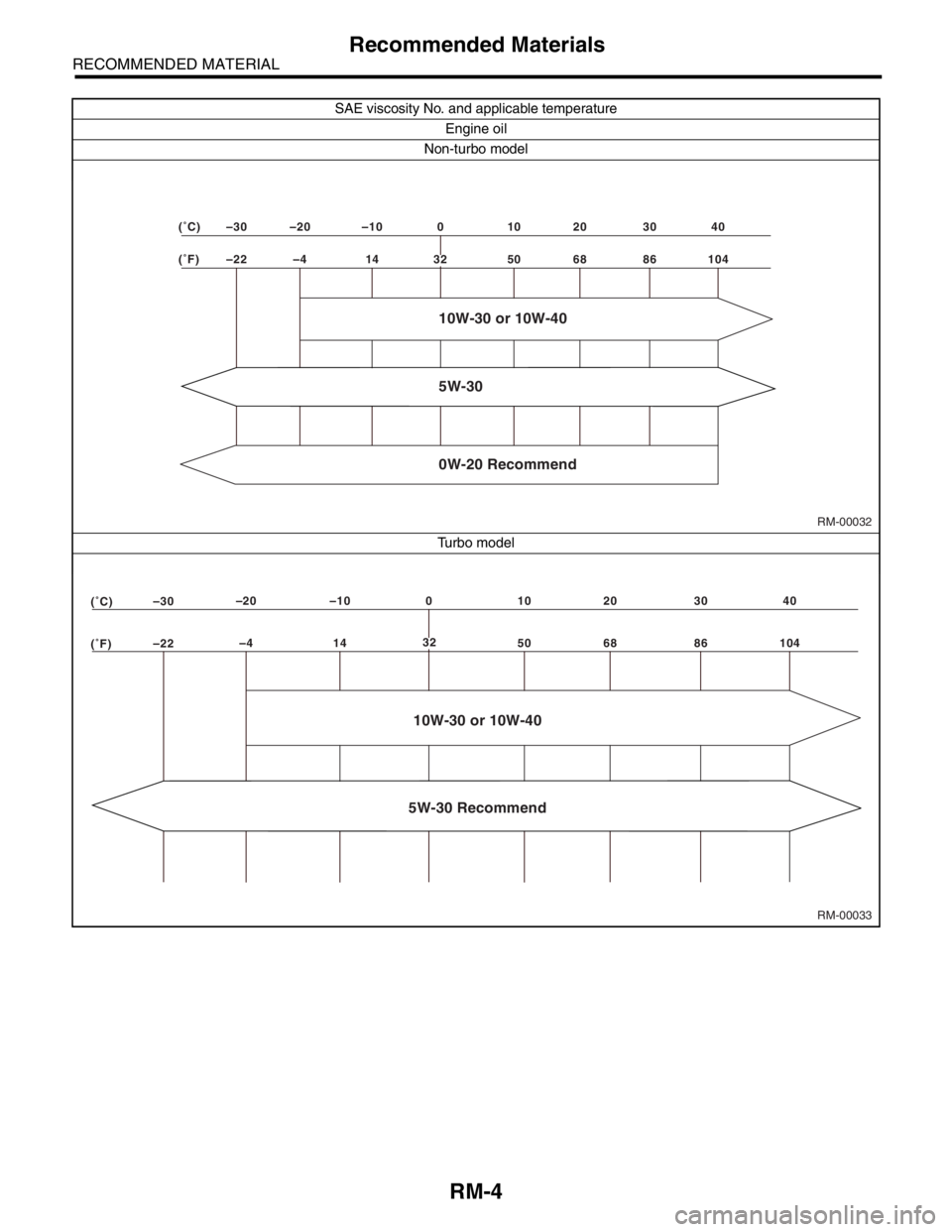
SAE viscosity No. and applicable temperature
Engine oil
Non-turbo model
Tu r b o m o d e l
RM-00032 (˚F) –22 –4 14 50 68 86 104 (˚C) –30 –20 –10 0 10 20 30 40
5W-30
32
10W-30 or 10W-40
0W-20 Recommend
RM-00033 (˚F)–22–4 14 50 68 86 104 (˚C)–30–20 –100
10 20 30 40
5W-30 Recommend
32
10W-30 or 10W-40
Page 733 of 2870
PI-10
PRE-DELIVERY INSPECTION
Pre-delivery Inspection
21.KEYLESS ENTRY SYSTEM
Check the keyless entry system operations as fol-
lows:
Fully open all the door windows.
Remove the key from the ignition switch and
close all the doors including rear gate.
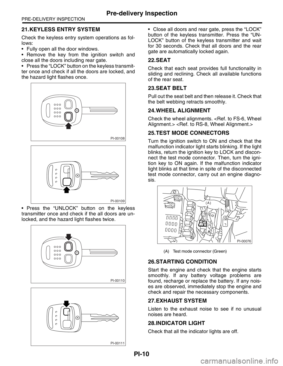
Press the “LOCK” button on the keyless transmit-
ter once and check if all the doors are locked, and
the hazard light flashes once.
Press the “UNLOCK” button on the keyless
transmitter once and check if the all doors are un-
locked, and the hazard light flashes twice. Close all doors and rear gate, press the “LOCK”
button of the keyless transmitter. Press the “UN-
LOCK” button of the keyless transmitter and wait
for 30 seconds. Check that all doors and the rear
gate are automatically locked again.
22.SEAT
Check that each seat provides full functionality in
sliding and reclining. Check all available functions
of the rear seat.
23.SEAT BELT
Pull out the seat belt and then release it. Check that
the belt webbing retracts smoothly.
24.WHEEL ALIGNMENT
Check the wheel alignments.
Alignment.>
25.TEST MODE CONNECTORS
Turn the ignition switch to ON and check that the
malfunction indicator light starts blinking. If the light
blinks, return the ignition key to LOCK and discon-
nect the test mode connector. Then, turn the igni-
tion key to ON again. If the malfunction indicator
light blinks at that time in spite of the disconnected
test mode connector, carry out an engine diagno-
sis.
26.STARTING CONDITION
Start the engine and check that the engine starts
smoothly. If any battery voltage problems are
found, recharge or replace the battery. If any nois-
es are observed, immediately stop the engine and
check and repair the necessary components.
27.EXHAUST SYSTEM
Listen to the exhaust noise to see if no unusual
noises are heard.
28.INDICATOR LIGHT
Check that all the indicator lights are off.
PI-00108
PI-00109
PI-00110
PI-00111
(A) Test mode connector (Green)
PI-00076
(A)
Page 757 of 2870
PM-20
PERIODIC MAINTENANCE SERVICE
Cooling System
11.Cooling System
A: INSPECTION
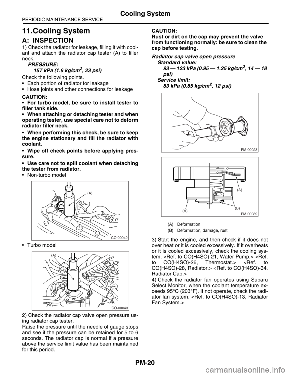
1) Check the radiator for leakage, filling it with cool-
ant and attach the radiator cap tester (A) to filler
neck.
PRESSURE:
157 kPa (1.6 kg/cm
2, 23 psi)
Check the following points.
Each portion of radiator for leakage
Hose joints and other connections for leakage
CAUTION:
For turbo model, be sure to install tester to
filler tank side.
When attaching or detaching tester and when
operating tester, use special care not to deform
radiator filler neck.
When performing this check, be sure to keep
the engine stationary and fill the radiator with
coolant.
Wipe off check points before applying pres-
sure.
Use care not to spill coolant when detaching
the tester from radiator.
Non-turbo model
Turbo model
2) Check the radiator cap valve open pressure us-
ing radiator cap tester.
Raise the pressure until the needle of gauge stops
and see if the pressure can be retained for 5 to 6
seconds. The radiator cap is normal if a pressure
above the service limit value has been maintained
for this period.CAUTION:
Rust or dirt on the cap may prevent the valve
from functioning normally: be sure to clean the
cap before testing.
Radiator cap valve open pressure
Standard value:
93 — 123 kPa (0.95 — 1.25 kg/cm2, 14 — 18
psi)
Service limit:
83 kPa (0.85 kg/cm
2, 12 psi)
3) Start the engine, and then check if it does not
over heat or it is cooled excessively. If it overheats
or it is cooled excessively, check the cooling sys-
tem.
to CO(H4SO)-26, Thermostat.>
CO(H4SO)-28, Radiator.>
Radiator Cap.>
4) Check the radiator fan operates using Subaru
Select Monitor, when the coolant temperature ex-
ceeds 95°C (203°F). If not operate, check the radi-
ator fan system.
Fan System.>
CO-00042
(A)
CO-00043
(A)
(A) Deformation
(B) Deformation, damage, rust
PM-00023
PM-00089
(B)
(A)(A)
Page 758 of 2870
PM-21
PERIODIC MAINTENANCE SERVICE
Engine Coolant
12.Engine Coolant
A: REPLACEMENT
1. REPLACEMENT OF ENGINE COOLANT
WARNING:
The radiator is of the pressurized type. Do not
attempt to open the radiator cap immediately
after the engine has been stopped.
1) Lift-up the vehicle.
2) Remove the under cover.
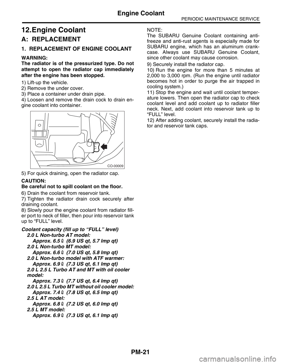
3) Place a container under drain pipe.
4) Loosen and remove the drain cock to drain en-
gine coolant into container.
5) For quick draining, open the radiator cap.
CAUTION:
Be careful not to spill coolant on the floor.
6) Drain the coolant from reservoir tank.
7) Tighten the radiator drain cock securely after
draining coolant.
8) Slowly pour the engine coolant from radiator fill-
er port to neck of filler, then pour into reservoir tank
up to “FULL” level.
Coolant capacity (fill up to “FULL” level)
2.0 L Non-turbo AT model:
Approx. 6.52 (6.9 US qt, 5.7 Imp qt)
2.0 L Non-turbo MT model:
Approx. 6.62 (7.0 US qt, 5.8 Imp qt)
2.0 L Non-turbo model with ATF warmer:
Approx. 6.92 (7.3 US qt, 6.1 Imp qt)
2.0 L 2.5 L Turbo AT and MT with oil cooler
model:
Approx. 7.32 (7.7 US qt, 6.4 Imp qt)
2.0 L 2.5 L Turbo MT without oil cooler model:
Approx. 7.42 (7.8 US qt, 6.5 Imp qt)
2.5 L AT model:
Approx. 6.82 (7.2 US qt, 6.0 Imp qt)
2.5 L MT model:
Approx. 6.92 (7.3 US qt, 6.1 Imp qt)NOTE:
The SUBARU Genuine Coolant containing anti-
freeze and anti-rust agents is especially made for
SUBARU engine, which has an aluminum crank-
case. Always use SUBARU Genuine Coolant,
since other coolant may cause corrosion.
9) Securely install the radiator cap.
10) Run the engine for more than 5 minutes at
2,000 to 3,000 rpm. (Run the engine until radiator
becomes hot in order to purge the air trapped in
cooling system.)
11) Stop the engine and wait until coolant temper-
ature lowers. Then open the radiator cap to check
coolant level and add coolant up to radiator filler
neck. Next, add coolant into reservoir tank up to
“FULL” level.
12) After adding coolant, securely install the radia-
tor and reservoir tank caps.
CO-00009
![SUBARU FORESTER 2004 Service Repair Manual IM-9
IMMOBILIZER (DIAGNOSTIC)
Clear Memory Mode
7. Clear Memory Mode
A: OPERATION
1) On the «Main Menu» display screen, select the
{Each System Check}, and then press the [YES] key.
2) On the «Syst](/manual-img/17/57426/w960_57426-650.png "SUBARU FORESTER 2004 Service Repair Manual IM-9
IMMOBILIZER (DIAGNOSTIC)
Clear Memory Mode
7. Clear Memory Mode
A: OPERATION
1) On the «Main Menu» display screen, select the
{Each System Check}, and then press the [YES] key.
2) On the «Syst")