2004 SUBARU FORESTER ECO mode
[x] Cancel search: ECO modePage 194 of 2870
AB-62
AIRBAG SYSTEM (DIAGNOSTIC)
Diagnostic Procedure with Diagnostic Trouble Code (DTC)
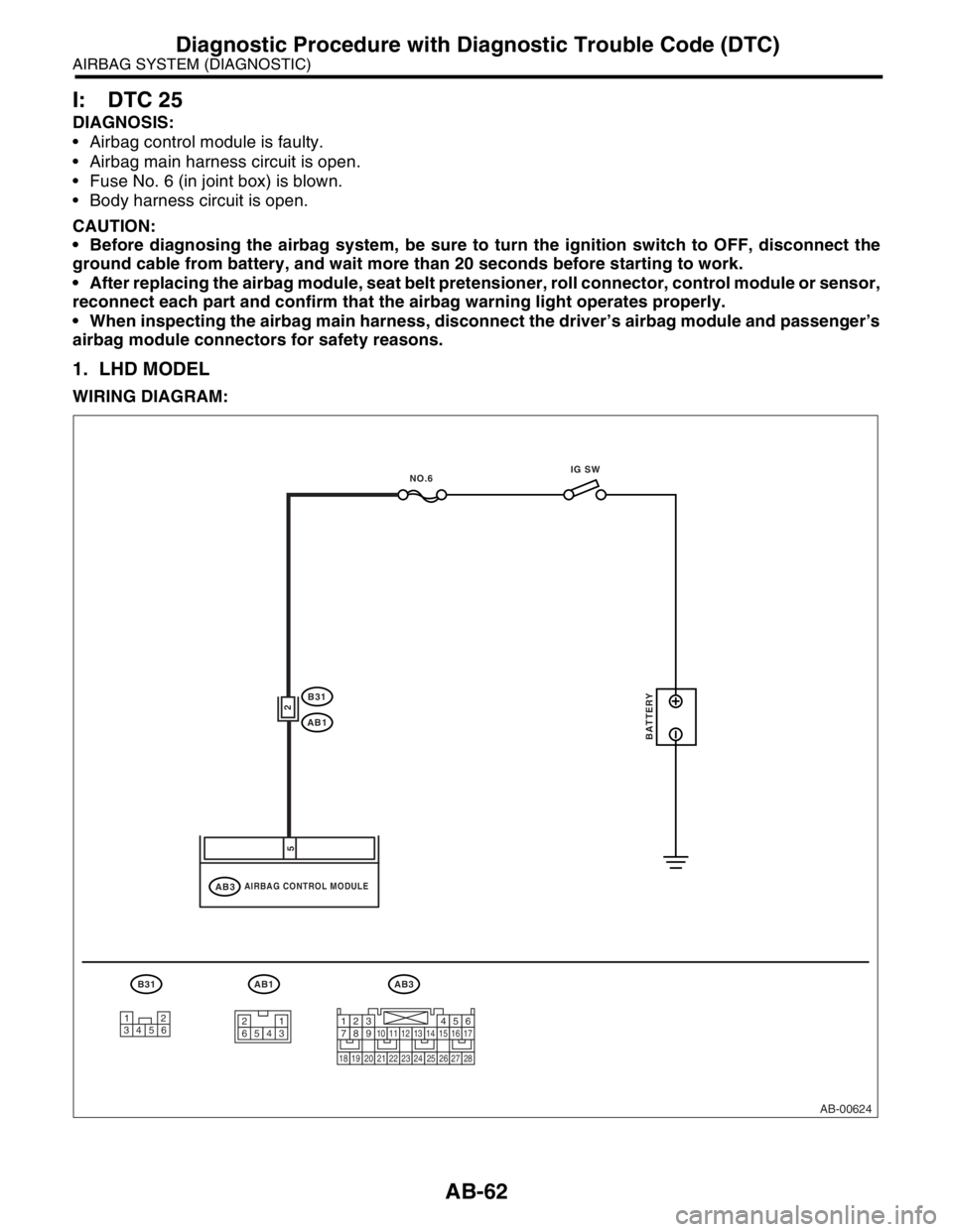
I: DTC 25
DIAGNOSIS:
Airbag control module is faulty.
Airbag main harness circuit is open.
Fuse No. 6 (in joint box) is blown.
Body harness circuit is open.
CAUTION:
Before diagnosing the airbag system, be sure to turn the ignition switch to OFF, disconnect the
ground cable from battery, and wait more than 20 seconds before starting to work.
After replacing the airbag module, seat belt pretensioner, roll connector, control module or sensor,
reconnect each part and confirm that the airbag warning light operates properly.
When inspecting the airbag main harness, disconnect the driver’s airbag module and passenger’s
airbag module connectors for safety reasons.
1. LHD MODEL
WIRING DIAGRAM:
AB-00624
AB3
AIRBAG CONTROL MODULEAB3
B31
AB1
AB1
2
5
BATTERY
IG SW
NO.6
B31
12
34561
23 45 61234567891011121314151617
1819202122232425262728
Page 199 of 2870

AB-67
AIRBAG SYSTEM (DIAGNOSTIC)
Diagnostic Procedure with Diagnostic Trouble Code (DTC)
Step Check Yes No
1 CHECK FRONT SUB-SENSOR (RH) AND
AIRBAG HARNESS.
1) Turn the ignition switch to OFF, disconnect
the battery ground cable, and wait more than
20 seconds.
2) Disconnect the connector (AB3) from the
airbag control module, and connect the con-
nector (1R) in test harness R.
3) Measure the resistance of the connector
(3R) in test harness R.
Connector & terminal
(3R) No. 7 — (3R) No. 9: Is the resistance 750 Ω and 1
KΩ? Replace the airbag
control module.
Module.>Go to step 2.
2 CHECK AIRBAG MAIN HARNESS AND
FRONT SUB-SENSOR HARNESS (RH).
1) Disconnect the connector (AB15) from the
front sub-sensor.
2) Connect the connector (IH) in test harness
H to connector (AB15).
3) Measure the resistance between connector
(3R) in test harness R and connector (3H) in
test harness H.
Connector & terminal
(3R) No. 7 — (3H) No. 5:
(3R) No. 9 — (3H) No. 6: Is the resistance less than 10
Ω?Go to step 3.LHD model:
Replace the airbag
main harness and
front sub-sensor
harness with body
harness.
RHD model:
Go to step 4.
3 CHECK AIRBAG MAIN HARNESS AND
FRONT SUB-SENSOR HARNESS (RH).
Measure the resistance between connector
(3R) in test harness R and the chassis ground.
Connector & terminal
(3R) No. 7 — Chassis ground:
(3R) No. 9 — Chassis ground: Is the resistance more than 1
MΩ?Go to step 8.LHD model:
Replace the airbag
main harness and
front sub-sensor
harness with body
harness.
RHD model:
Go to step 4.
4 CHECK AIRBAG MAIN HARNESS
1) Disconnect the connector (AB13) from
(AB14), and connect the connector (1L) in test
harness L to connector (AB13).
2) Measure the resistance between connector
(3R) in test harness R and connector (3L) in
test harness L.
Connector & terminal
(3R) No. 7 — (3L) No. 4:
(3R) No. 9 — (3L) No. 3: Is the resistance less than 10
Ω?Go to step 5.Replace the airbag
main harness with
body harness.
5 CHECK AIRBAG MAIN HARNESS
Measure the resistance between connector
(3R) in test harness R and the chassis ground.
Connector & terminal
(3R) No. 7 — Chassis ground:
(3R) No. 9 — Chassis ground:Is the resistance more than 1
MΩ?Go to step 6.Replace the airbag
main harness with
body harness.
6 CHECK FRONT SUB-SENSOR HARNESS
(RH).
1) Connect the connector (2L) in test harness
F to the connector (AB14).
2) Measure the resistance between connector
(3H) in test harness H and connector (3L) in
the test harness L.
Connector & terminal
(3L) No. 5 — (3H) No. 5:
(3L) No. 6 — (3H) No. 6: Is the resistance less than 10
Ω?Go to step 7.Replace the front
sub-sensor har-
ness (RH) with
body harness.
Page 202 of 2870

AB-70
AIRBAG SYSTEM (DIAGNOSTIC)
Diagnostic Procedure with Diagnostic Trouble Code (DTC)
Step Check Yes No
1 CHECK FRONT SUB-SENSOR (LH) AND
AIRBAG HARNESS.
1) Turn the ignition switch to OFF, disconnect
the battery ground cable, and wait more than
20 seconds.
2) Disconnect the connector (AB3) from the
airbag control module, and connect connector
(1R) in the test harness R to connector (AB3).
3) Measure the resistance of the connector
(3R) in the test harness R.
Connector & terminal
(3R) No. 6 — (3R) No. 8: Is the resistance 750 Ω and 1
KΩ?Replace the airbag
control module.
Module.>Go to step 2.
2 CHECK AIRBAG MAIN HARNESS AND
FRONT SUB-SENSOR HARNESS (LH).
1) Disconnect the connector (AB18) from the
front sub-sensor.
2) Connect the connector (1H) in test harness
H to connector (AB18).
3) Measure the resistance between connector
(3R) in test harness R and connector (3H) in
test harness H.
Connector & terminal
(3R) No. 6 — (3H) No. 5:
(3R) No. 8 — (3H) No. 6: Is the resistance less than 10
Ω?Go to step 3.LHD model:
Go to step 4.
RHD model:
Replace the airbag
main harness and
front sub-sensor
harness with body
harness.
3 CHECK AIRBAG MAIN HARNESS AND
FRONT SUB-SENSOR HARNESS (LH).
Measure the resistance between connector
(3R) in test harness R and the chassis ground.
Connector & terminal
(3R) No. 6 — Chassis ground:
(3R) No. 8 — Chassis ground: Is the resistance more than 1
MΩ?Go to step 8.LHD model:
Go to step 4.
RHD model:
Replace the airbag
main harness and
front sub-sensor
harness with body
harness.
4 CHECK AIRBAG MAIN HARNESS
1) Disconnect the connector (AB13) from
(AB14), and connect the connector (1L) in test
harness L to connector (AB13).
2) Measure the resistance between connector
(3R) in test harness R and connector (3L) in
test harness L.
Connector & terminal
(3R) No. 6 — (3L) No. 4:
(3R) No. 8 — (3L) No. 3: Is the resistance less than 10
Ω?Go to step 5.Replace the airbag
main harness with
body harness.
5 CHECK AIRBAG MAIN HARNESS
Measure the resistance between connector
(3R) in test harness R and the chassis ground.
Connector & terminal
(3R) No. 6 — Chassis ground:
(3R) No. 8 — Chassis ground:Is the resistance more than 1
MΩ?Go to step 6.Replace the airbag
main harness with
body harness.
6 CHECK FRONT SUB-SENSOR HARNESS
(LH).
1) Connect the connector (2L) in test harness
L to the connector (AB14).
2) Measure the resistance between connector
(3H) in test harness H and connector (3L) in
the test harness L.
Connector & terminal
(3L) No. 5 — (3H) No. 5:
(3L) No. 6 — (3H) No. 6: Is the resistance less than 10
Ω?Go to step 7.Replace the front
sub-sensor har-
ness (LH) with
body harness.
Page 229 of 2870
AB-97
AIRBAG SYSTEM (DIAGNOSTIC)
Diagnostic Procedure with Diagnostic Trouble Code (DTC)
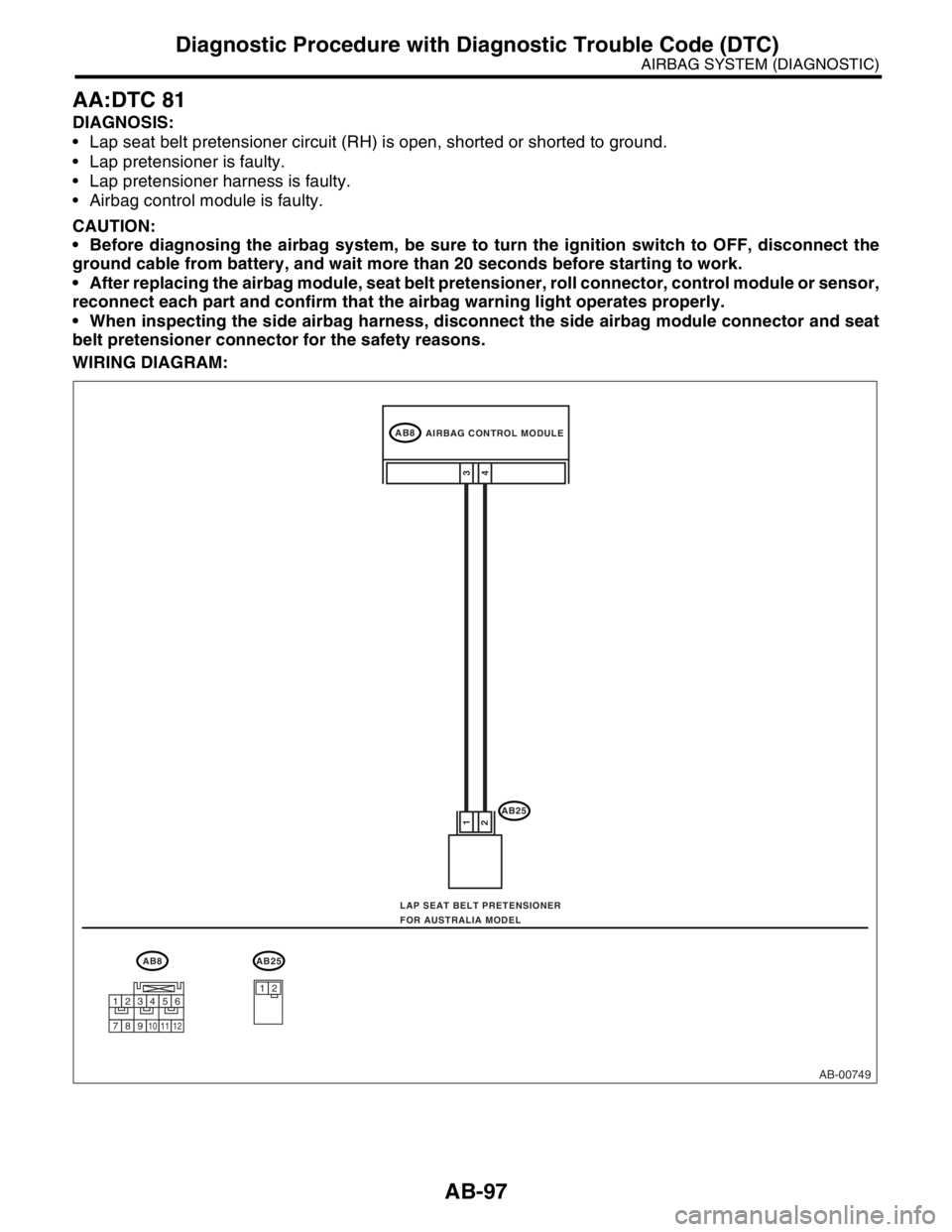
AA:DTC 81
DIAGNOSIS:
Lap seat belt pretensioner circuit (RH) is open, shorted or shorted to ground.
Lap pretensioner is faulty.
Lap pretensioner harness is faulty.
Airbag control module is faulty.
CAUTION:
Before diagnosing the airbag system, be sure to turn the ignition switch to OFF, disconnect the
ground cable from battery, and wait more than 20 seconds before starting to work.
After replacing the airbag module, seat belt pretensioner, roll connector, control module or sensor,
reconnect each part and confirm that the airbag warning light operates properly.
When inspecting the side airbag harness, disconnect the side airbag module connector and seat
belt pretensioner connector for the safety reasons.
WIRING DIAGRAM:
AB-00749
AB8
AB25
4 1
23
AB8AB25
12
AIRBAG CONTROL MODULE
LAP SEAT BELT PRETENSIONER
FOR AUSTRALIA MODEL
123456
789101112
Page 231 of 2870
AB-99
AIRBAG SYSTEM (DIAGNOSTIC)
Diagnostic Procedure with Diagnostic Trouble Code (DTC)
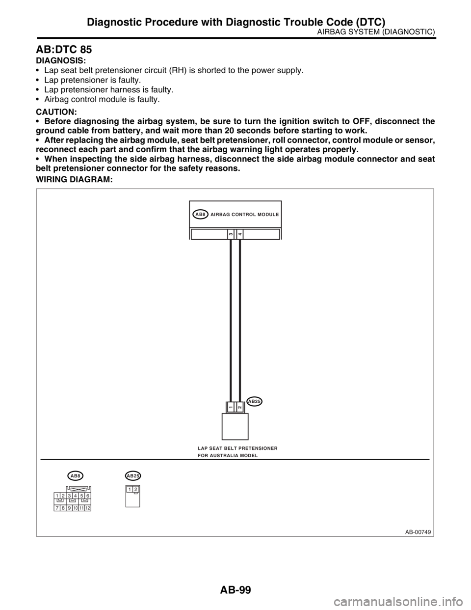
AB:DTC 85
DIAGNOSIS:
Lap seat belt pretensioner circuit (RH) is shorted to the power supply.
Lap pretensioner is faulty.
Lap pretensioner harness is faulty.
Airbag control module is faulty.
CAUTION:
Before diagnosing the airbag system, be sure to turn the ignition switch to OFF, disconnect the
ground cable from battery, and wait more than 20 seconds before starting to work.
After replacing the airbag module, seat belt pretensioner, roll connector, control module or sensor,
reconnect each part and confirm that the airbag warning light operates properly.
When inspecting the side airbag harness, disconnect the side airbag module connector and seat
belt pretensioner connector for the safety reasons.
WIRING DIAGRAM:
AB-00749
AB8
AB25
4 1
23
AB8AB25
12
AIRBAG CONTROL MODULE
LAP SEAT BELT PRETENSIONER
FOR AUSTRALIA MODEL
123456
789101112
Page 410 of 2870
SE-6
SEAT
Front Seat
2. Front Seat
A: REMOVAL
1) Disconnect the ground cable from battery.
WARNING:
The airbag system is fitted with a backup power
source. If the airbag system is serviced within 20
seconds after the ground cable is disconnected,
it may inflate.
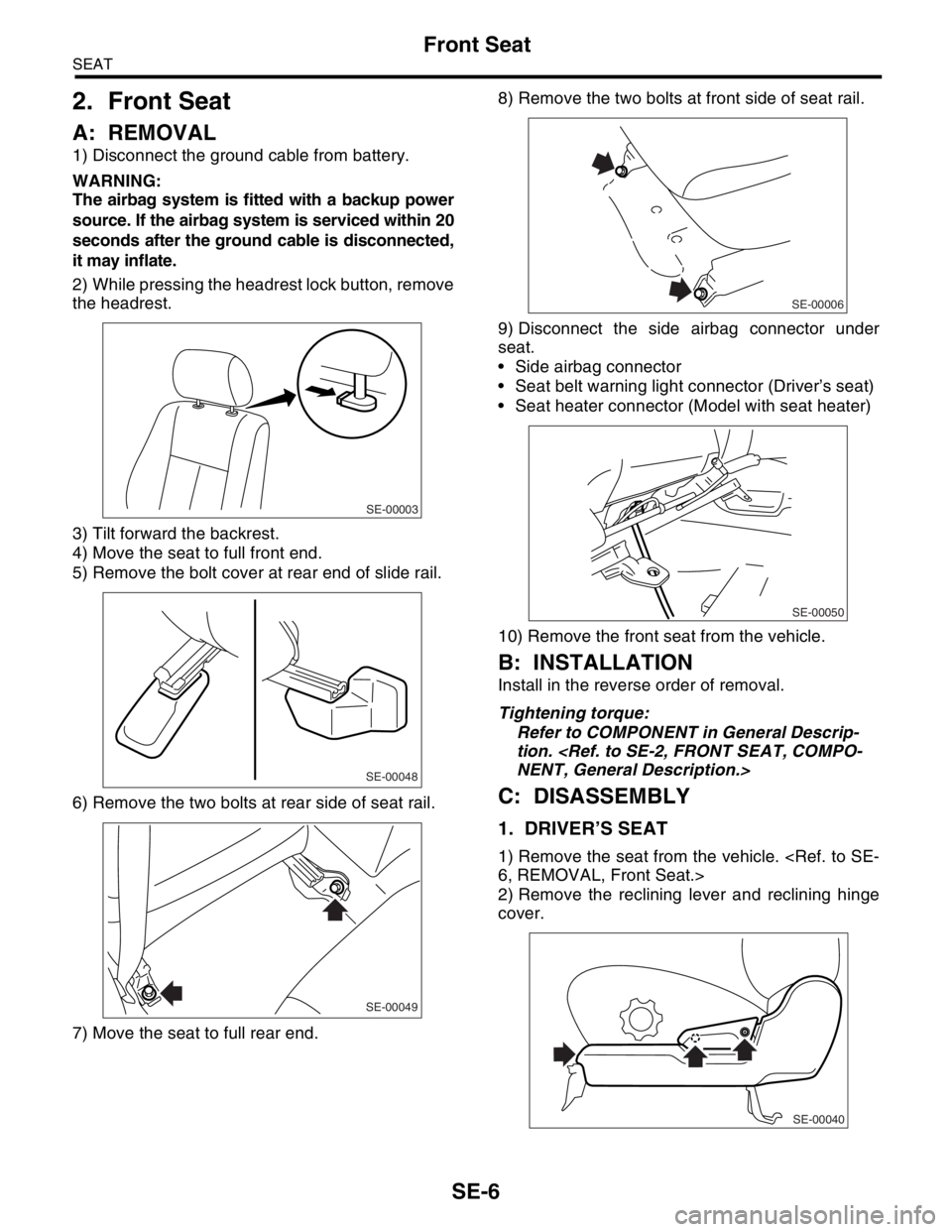
2) While pressing the headrest lock button, remove
the headrest.
3) Tilt forward the backrest.
4) Move the seat to full front end.
5) Remove the bolt cover at rear end of slide rail.
6) Remove the two bolts at rear side of seat rail.
7) Move the seat to full rear end.8) Remove the two bolts at front side of seat rail.
9) Disconnect the side airbag connector under
seat.
Side airbag connector
Seat belt warning light connector (Driver’s seat)
Seat heater connector (Model with seat heater)
10) Remove the front seat from the vehicle.
B: INSTALLATION
Install in the reverse order of removal.
Tightening torque:
Refer to COMPONENT in General Descrip-
tion.
C: DISASSEMBLY
1. DRIVER’S SEAT
1) Remove the seat from the vehicle.
2) Remove the reclining lever and reclining hinge
cover.
SE-00003
SE-00048
SE-00049
SE-00006
SE-00050
SE-00040
Page 427 of 2870
SL-7
SECURITY AND LOCK
General Description
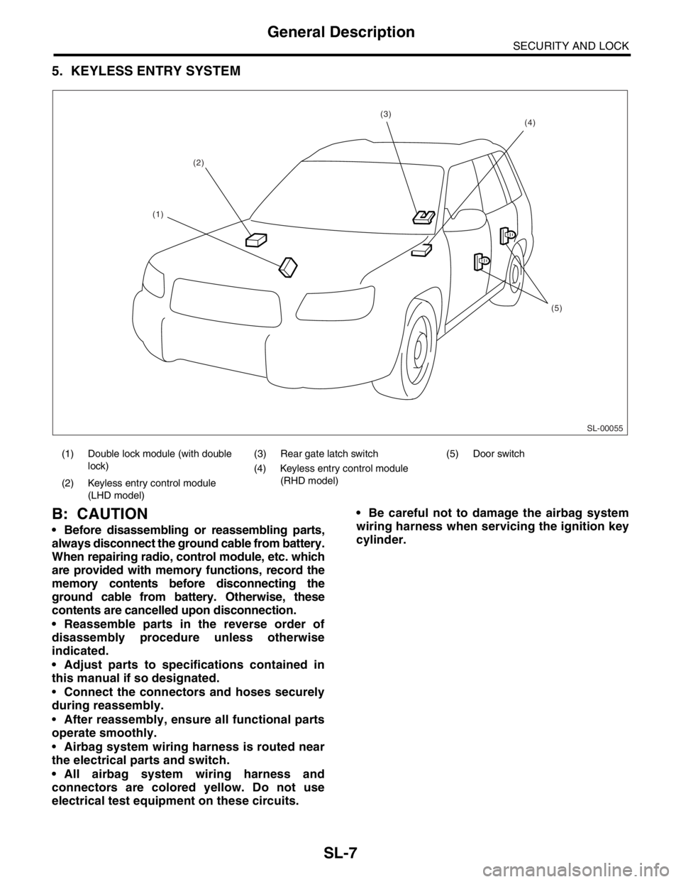
5. KEYLESS ENTRY SYSTEM
B: CAUTION
Before disassembling or reassembling parts,
always disconnect the ground cable from battery.
When repairing radio, control module, etc. which
are provided with memory functions, record the
memory contents before disconnecting the
ground cable from battery. Otherwise, these
contents are cancelled upon disconnection.
Reassemble parts in the reverse order of
disassembly procedure unless otherwise
indicated.
Adjust parts to specifications contained in
this manual if so designated.
Connect the connectors and hoses securely
during reassembly.
After reassembly, ensure all functional parts
operate smoothly.
Airbag system wiring harness is routed near
the electrical parts and switch.
All airbag system wiring harness and
connectors are colored yellow. Do not use
electrical test equipment on these circuits. Be careful not to damage the airbag system
wiring harness when servicing the ignition key
cylinder.
(1) Double lock module (with double
lock)(3) Rear gate latch switch (5) Door switch
(4) Keyless entry control module
(RHD model)
(2) Keyless entry control module
(LHD model)
SL-00055
(2)
(5)
(4)(3)
(1)
Page 644 of 2870

IM-2
IMMOBILIZER (DIAGNOSTIC)
Basic Diagnostic Procedure
1. Basic Diagnostic Procedure
A: PROCEDURE
Step Check Yes No
1 CHECK ILLUMINATION OF IMMOBILIZER
WARNING LIGHT.
1) Turn the ignition switch to OFF or ACC
position.
2) Wait at least 60 seconds.Does the immobilizer warning
light blink?Go to step 2.Check the immobi-
lizer warning light
circuit.
IMMOBILIZER
WARNING CIR-
CUIT, INSPEC-
TION, Diagnostics
Chart for Immobi-
lizer Warning
Light.>
2 CHECK ILLUMINATION OF IMMOBILIZER
WARNING LIGHT.
Remove the key from ignition switch.Does the immobilizer warning
light begin to blink within 1 sec-
ond after the key is removed?Go to step 3.Check the key
switch circuit.
WARNING
SWITCH CIR-
CUIT, INSPEC-
TION, Diagnostics
Chart for Immobi-
lizer Warning
Light.>
3 CHECK ENGINE START.
Turn the ignition switch to START position.Does the engine start? Go to step 4.Go to step 5.
4 CHECK ILLUMINATION OF IMMOBILIZER
WARNING LIGHT.
Turn the ignition switch to ON.Does the immobilizer warning
light illuminate?Check the immobi-
lizer warning light
circuit.
IMMOBILIZER
WARNING CIR-
CUIT, INSPEC-
TION, Diagnostics
Chart for Immobi-
lizer Warning
Light.>Immobilizer sys-
tem is normal.
5 CHECK INDICATION OF DTC ON DISPLAY.
1) Turn the ignition switch to OFF.
2) Connect the Subaru Select Monitor to data
link connector.
3) Turn the ignition switch and Subaru Select
Monitors witch to ON.
4) Read any DTC on the display. Are DTCs indicated on dis-
play?Go to step 6.Repair the related
parts.
6 PERFORM THE DIAGNOSIS.
1) Inspect using “Diagnostics Chart with Trou-
ble Code”.
2) Repair the trouble cause.
3) Perform the clear memory mode.
4) Read any DTC again.Are DTCs indicated on dis-
play?Inspect using
“Diagnostic Proce-
dure with Diagnos-
tic Trouble Code
(DTC)”.
tics Procedure
with Diagnostic
Trouble Code
(DTC).>Finish the diag-
nostics.