Page 1931 of 2870

FUEL INJECTION (FUEL SYSTEM)
FU(H4DOTC 2.5)
Page
1. General Description ....................................................................................2
2. Throttle Body .............................................................................................13
3. Intake Manifold ..........................................................................................14
4. Engine Coolant Temperature Sensor........................................................26
5. Crankshaft Position Sensor.......................................................................27
6. Camshaft Position Sensor.........................................................................28
7. Knock Sensor ............................................................................................29
8. Mass Air Flow and Intake Air Temperature Sensor ..................................30
9. Manifold Absolute Pressure Sensor ..........................................................31
10. Fuel Injector ..............................................................................................32
11. Tumble Generator Valve Assembly ..........................................................33
12. Tumble Generator Valve Actuator.............................................................34
13. Wastegate Control Solenoid Valve ...........................................................35
14. Front Oxygen (A/F) Sensor .......................................................................36
15. Rear Oxygen Sensor.................................................................................38
16. Exhaust Temperature Sensor ...................................................................40
17. Engine Control Module (ECM) ..................................................................41
18. Main Relay ................................................................................................42
19. Fuel Pump Relay.......................................................................................43
20. Fuel Pump Control Unit .............................................................................44
21. Fuel ...........................................................................................................45
22. Fuel Tank ..................................................................................................46
23. Fuel Filler Pipe ..........................................................................................48
24. Fuel Pump .................................................................................................52
25. Fuel Level Sensor .....................................................................................54
26. Fuel Sub Level Sensor ..............................................................................55
27. Fuel Filter ..................................................................................................57
28. Fuel Cut Valve...........................................................................................58
29. Fuel Damper Valve ...................................................................................59
30. Fuel Delivery, Return and Evaporation Lines............................................60
31. Fuel System Trouble in General ...............................................................63
Page 1949 of 2870

FU(H4DOTC 2.5)-19
FUEL INJECTION (FUEL SYSTEM)
Intake Manifold
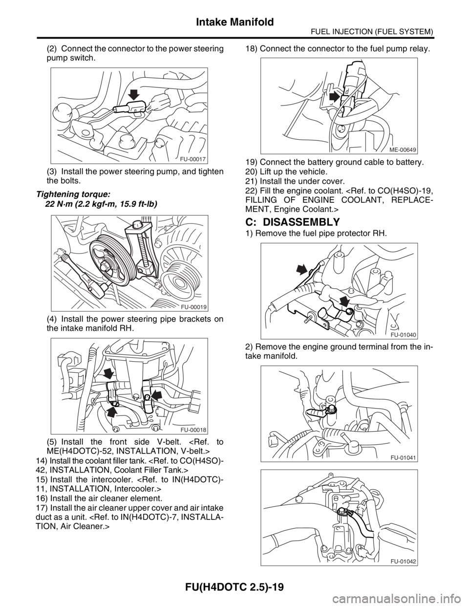
(2) Connect the connector to the power steering
pump switch.
(3) Install the power steering pump, and tighten
the bolts.
Tightening torque:
22 N·m (2.2 kgf-m, 15.9 ft-lb)
(4) Install the power steering pipe brackets on
the intake manifold RH.
(5) Install the front side V-belt.
ME(H4DOTC)-52, INSTALLATION, V-belt.>
14) Install the coolant filler tank.
42, INSTALLATION, Coolant Filler Tank.>
15) Install the intercooler.
11, INSTALLATION, Intercooler.>
16) Install the air cleaner element.
17) Install the air cleaner upper cover and air intake
duct as a unit.
TION, Air Cleaner.>18) Connect the connector to the fuel pump relay.
19) Connect the battery ground cable to battery.
20) Lift up the vehicle.
21) Install the under cover.
22) Fill the engine coolant.
FILLING OF ENGINE COOLANT, REPLACE-
MENT, Engine Coolant.>
C: DISASSEMBLY
1) Remove the fuel pipe protector RH.
2) Remove the engine ground terminal from the in-
take manifold.
FU-00017
FU-00019
FU-00018
ME-00649
FU-01040
FU-01041
FU-01042
Page 1972 of 2870
FU(H4DOTC 2.5)-42
FUEL INJECTION (FUEL SYSTEM)
Main Relay
18.Main Relay
A: REMOVAL
1) Disconnect the ground cable from battery.
2) Remove the glove box.
AL, Glove Box.>
3) Remove the bolt which holds the main relay
bracket on the body.
4) Disconnect the connectors from the main relay.
B: INSTALLATION
Install in the reverse order of removal.
FU-00009
FU-00317
Page 1973 of 2870
FU(H4DOTC 2.5)-43
FUEL INJECTION (FUEL SYSTEM)
Fuel Pump Relay
19.Fuel Pump Relay
A: REMOVAL
1) Disconnect the ground cable from battery.
2) Remove the glove box.
AL, Glove Box.>
3) Remove the bolt which holds fuel pump relay
bracket on the body.
4) Disconnect the connector from the fuel pump re-
lay.
5) Remove the fuel pump relay from the mounting
bracket.
B: INSTALLATION
Install in the reverse order of removal.
FU-00009
FU-00262
Page 1975 of 2870
FU(H4DOTC 2.5)-45
FUEL INJECTION (FUEL SYSTEM)
Fuel
21.Fuel
A: OPERATION
1. RELEASING OF FUEL PRESSURE
WARNING:
Place “NO FIRE” signs near the working area.
Be careful not to spill fuel on the floor.
1) Disconnect the connector from fuel pump relay.
2) Start the engine and run it until it stalls.
3) After the engine stalls, crank it for 5 more seconds.
4) Turn the ignition switch to OFF.
2. DRAINING FUEL
WARNING:
Place “NO FIRE” signs near the working area.
Be careful not to spill fuel on the floor.
1) Set the vehicle on a lift.
2) Disconnect the ground cable from battery.
3) Open the fuel filler flap lid and remove fuel filler
cap.
4) Lift-up the vehicle.5) Drain fuel from the fuel tank.
Set a container under the vehicle and remove the
drain plug from fuel tank.
6) Tighten the fuel drain plug.
Tightening torque:
26 N·m (2.7 kgf-m, 19.2 ft-lb)
FU-00262
FU-00009
FU-00089
FU-00089
Page 1977 of 2870

FU(H4DOTC 2.5)-47
FUEL INJECTION (FUEL SYSTEM)
Fuel Tank
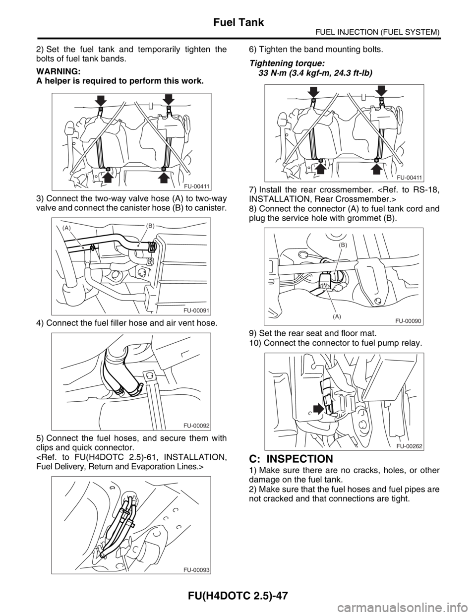
2) Set the fuel tank and temporarily tighten the
bolts of fuel tank bands.
WARNING:
A helper is required to perform this work.
3) Connect the two-way valve hose (A) to two-way
valve and connect the canister hose (B) to canister.
4) Connect the fuel filler hose and air vent hose.
5) Connect the fuel hoses, and secure them with
clips and quick connector.
Fuel Delivery, Return and Evaporation Lines.>6) Tighten the band mounting bolts.
Tightening torque:
33 N·m (3.4 kgf-m, 24.3 ft-lb)
7) Install the rear crossmember.
INSTALLATION, Rear Crossmember.>
8) Connect the connector (A) to fuel tank cord and
plug the service hole with grommet (B).
9) Set the rear seat and floor mat.
10) Connect the connector to fuel pump relay.
C: INSPECTION
1) Make sure there are no cracks, holes, or other
damage on the fuel tank.
2) Make sure that the fuel hoses and fuel pipes are
not cracked and that connections are tight.
FU-00411
(A)(B)
FU-00091
FU-00092
FU-00093
FU-00411
(B)
(A)
FU-00090
FU-00262
Page 1980 of 2870
FU(H4DOTC 2.5)-50
FUEL INJECTION (FUEL SYSTEM)
Fuel Filler Pipe
6) Insert the fuel filler hose (A) approx. 35 to 40 mm
(1.38 to 1.57 in) over the lower end of fuel filler pipe
and tighten the clamp.
CAUTION:
Do not allow clips to touch the air vent hose (B)
and rear suspension crossmember.
7) Insert the air vent hose approx. 25 to 30 mm
(0.98 to 1.18 in) into the lower end of air vent pipe
and hold clip.
L = 27.5
±2.5 mm (1.083±0.098 in)
8) Tighten the bolt which holds fuel filler pipe brack-
et on body.
Tightening torque:
7.5 N·m (0.75 kgf-m, 5.4 ft-lb)9) Hold the evaporation hoses onto clip of fuel filler
pipe.
10) Install the fuel filler pipe protector.
11) Install the rear right wheel.
12) Lower the vehicle.
13) Tighten the wheel nuts.
14) Connect the connector to fuel pump relay.
(1) Hose
(2) Clip
(3) Pipe
(A)
(B)
FU-00101
FU-00104
(1)(2)
L/2
L(3)
FU-00100
FU-00098
FU-00097
FU-00096
FU-00262
Page 2029 of 2870

EN(H4DOTC 2.5)-5
ENGINE (DIAGNOSTIC)
General Description
3. General Description
A: CAUTION
1) Airbag system wiring harness is routed near the
ECM, main relay and fuel pump relay.
CAUTION:
All airbag system wiring harness and con-
nectors are all colored yellow. Do not use the
electrical test equipment on these circuits.
Be careful not to damage the Airbag system
wiring harness when servicing the ECM, TCM,
main relay and fuel pump relay.
2) Never connect the battery in reverse polarity.
The ECM will be destroyed immediately.
The fuel injector and other part will be damaged.
3) Do not disconnect the battery terminals while the
engine is running.
A large counter electromotive force will be gener-
ated in the generator, and this voltage may damage
electronic parts such as ECM, etc.
4) Before disconnecting the connectors of each
sensor and the ECM, be sure to turn OFF the igni-
tion switch.
5) Poor contact has been identified as a primary
cause of this problem. Measure the voltage or re-
sistance of individual sensor or all electrical control
modules using a tapered pin with a diameter of less
than 0.64 mm (0.025 in). Do not insert the pin more
than 5 mm (0.20 in) into the part.
6) Remove the ECM from the located position after
disconnecting two cables on battery.
Otherwise, the ECM may be damaged.
CAUTION:
When replacing the ECM, be careful not to use
the wrong spec. ECM to avoid damaging the
fuel injection system.
7) Connectors to each sensor in the engine com-
partment and the harness connectors on the en-
gine side and body side are all designed to be
waterproof. However, take care not to allow water
to get into the connectors when washing the vehi-
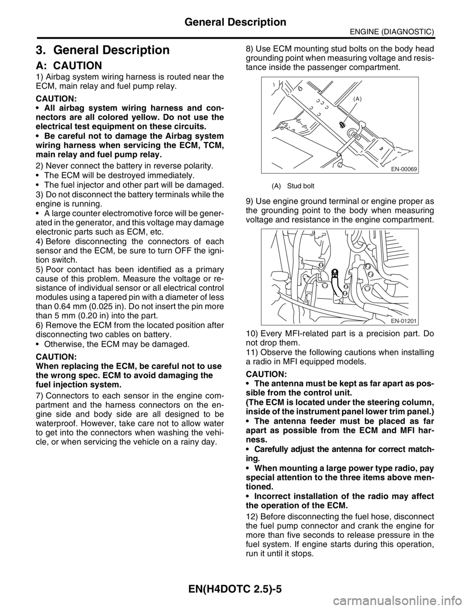
cle, or when servicing the vehicle on a rainy day. 8) Use ECM mounting stud bolts on the body head
grounding point when measuring voltage and resis-
tance inside the passenger compartment.
9) Use engine ground terminal or engine proper as
the grounding point to the body when measuring
voltage and resistance in the engine compartment.
10) Every MFI-related part is a precision part. Do
not drop them.
11) Observe the following cautions when installing
a radio in MFI equipped models.
CAUTION:
The antenna must be kept as far apart as pos-
sible from the control unit.
(The ECM is located under the steering column,
inside of the instrument panel lower trim panel.)
The antenna feeder must be placed as far
apart as possible from the ECM and MFI har-
ness.
Carefully adjust the antenna for correct match-
ing.
When mounting a large power type radio, pay
special attention to the three items above men-
tioned.
Incorrect installation of the radio may affect
the operation of the ECM.
12) Before disconnecting the fuel hose, disconnect
the fuel pump connector and crank the engine for
more than five seconds to release pressure in the
fuel system. If engine starts during this operation,
run it until it stops.
(A) Stud bolt
EN-00069
(A)
EN-01201