2004 SUBARU FORESTER transmission oil
[x] Cancel search: transmission oilPage 2806 of 2870
5MT-93
MANUAL TRANSMISSION AND DIFFERENTIAL
Drive Pinion Shaft Assembly
E: INSPECTION
Disassembled parts should be washed clean first
and then inspected carefully.
1) Bearings
Replace the bearings in the following cases:
Bearings whose balls, outer races and inner rac-
es are broken or rusty.
Worn bearings
Bearings that fail to turn smoothly or make noise
when turned after gear oil lubrication.
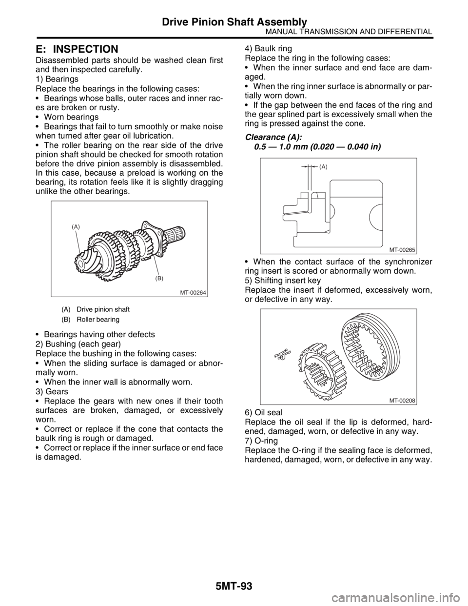
The roller bearing on the rear side of the drive
pinion shaft should be checked for smooth rotation
before the drive pinion assembly is disassembled.
In this case, because a preload is working on the
bearing, its rotation feels like it is slightly dragging
unlike the other bearings.
Bearings having other defects
2) Bushing (each gear)
Replace the bushing in the following cases:
When the sliding surface is damaged or abnor-
mally worn.
When the inner wall is abnormally worn.
3) Gears
Replace the gears with new ones if their tooth
surfaces are broken, damaged, or excessively
worn.
Correct or replace if the cone that contacts the
baulk ring is rough or damaged.
Correct or replace if the inner surface or end face
is damaged.4) Baulk ring
Replace the ring in the following cases:
When the inner surface and end face are dam-
aged.
When the ring inner surface is abnormally or par-
tially worn down.
If the gap between the end faces of the ring and
the gear splined part is excessively small when the
ring is pressed against the cone.
Clearance (A):
0.5 — 1.0 mm (0.020 — 0.040 in)
When the contact surface of the synchronizer
ring insert is scored or abnormally worn down.
5) Shifting insert key
Replace the insert if deformed, excessively worn,
or defective in any way.
6) Oil seal
Replace the oil seal if the lip is deformed, hard-
ened, damaged, worn, or defective in any way.
7) O-ring
Replace the O-ring if the sealing face is deformed,
hardened, damaged, worn, or defective in any way.
(A) Drive pinion shaft
(B) Roller bearing
MT-00264
(A)
(B)
MT-00265
(A)
MT-00208
Page 2809 of 2870

5MT-96
MANUAL TRANSMISSION AND DIFFERENTIAL
Front Differential Assembly
21.Front Differential Assembly
A: REMOVAL
1) Remove the manual transmission assembly
from vehicle.
2) Remove the transfer case with extension case
assembly.
3) Remove the transmission case.
4) Remove the drive pinion shaft assembly.
bly.>
5) Remove the main shaft assembly.
Single-range model
Dual-range model
6) Remove the differential assembly.
NOTE:
Be careful not to confuse the right and left roller
bearing outer races.
Be careful not to damage the retainer oil seal.
7) Remove the differential side retainers using ST.
ST 499787000 WRENCH ASSY
8) Remove the bearing outer race from transmis-
sion case.
ST 398527700 PULLER ASSY
B: INSTALLATION
1) Insert the bearing outer race to transmission
case.
NOTE:
Apply the transmission gear oil to outer surface of
bearing outer race.
2) Install the differential side retainers using ST.
ST 499787000 WRENCH ASSY
3) Install the differential assembly.
NOTE:
Be careful not to fold the sealing lip of oil seal.
Wrap the right and left spline sections of axle
shaft with vinyl tape to prevent scratches.
4) Install the main shaft assembly.
gle-Range.>
5) Install the drive pinion assembly.
gle-Range.>
6) Install the transmission case.
7) Install the transfer case with extension case as-
sembly.
8) Install the manual transmission assembly to ve-
hicle.
MT-00162
MT-00176
ST
MT-00162
Page 2811 of 2870

5MT-98
MANUAL TRANSMISSION AND DIFFERENTIAL
Front Differential Assembly
2. SIDE RETAINER
NOTE:
Replace the oil seal and O-ring after adjustment of
drive pinion gear backlash and tooth contact.
1) Remove the O-ring.
2) Remove the oil seal.
NOTE:
Remove the oil seal using a flat tip screwdriver
Do not reuse the oil seal. Prepare a new oil seal.
D: ASSEMBLY
1. DIFFERENTIAL CASE ASSEMBLY
1) Install the differential bevel gear and bevel pin-
ion together with washers, and insert pinion shaft.
NOTE:
Face the chamfered side of washer toward gear.2) Measure the backlash between differential bevel
gear and pinion. If it is not within specifications, in-
stall a suitable washer to adjust it.
NOTE:
Be sure the pinion gear tooth contacts adjacent
gear teeth during measurement.
ST1 498247001 MAGNET BASE
ST2 498247100 DIAL GAUGE
Standard backlash:
0.13 — 0.18 mm (0.0051 — 0.0071 in)
3) Align the pinion shaft and differential case at
their holes, and drive the straight pin into holes
from the hypoid driven gear side, using ST.
NOTE:
Lock the straight pin after installing.
ST 899904100 REMOVER
(A) Differential bevel pinion
(B) Differential bevel gear
(C) Pinion shaft
MT-00279
MT-01003
MT-00284
(A) (B)
(C)
(A) Pinion shaft
(B) Differential case
(C) Straight pin
MT-00285
ST1
ST2
MT-00286
(A)
(C)
(B)
Page 2812 of 2870
5MT-99
MANUAL TRANSMISSION AND DIFFERENTIAL
Front Differential Assembly
4) Install the roller bearing to differential case.
CAUTION:
Do not apply load in excess of 10 kN (1 ton, 1.1
US ton, 1.0 Imp ton).
NOTE:
Be careful because the roller bearing outer races
are used as a set.
ST1 499277100 BUSH 1-2 INSTALLER
ST2 398497701 ADAPTER
5) Install the hypoid driven gear to differential case
using twelve bolts.
Tightening torque:
T: 62 N·m (6.3 kgf-m, 45.6 ft-lb)2. SIDE RETAINER
1) Install a new oil seal.
ST 18675AA000 DIFFERENTIAL OIL SEAL IN-
STALLER
CAUTION:
When pressing fit the oil seal to side retainer,
tap it to press fit using a plastic hammer.
Do not use the press.
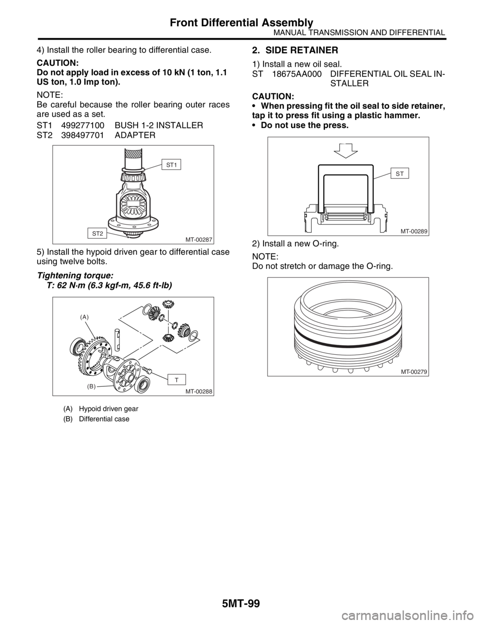
2) Install a new O-ring.
NOTE:
Do not stretch or damage the O-ring.
(A) Hypoid driven gear
(B) Differential case
MT-00287
ST1
ST2
MT-00288
(B) (A)T
MT-00289
ST
MT-00279
Page 2813 of 2870

5MT-100
MANUAL TRANSMISSION AND DIFFERENTIAL
Front Differential Assembly
E: INSPECTION
Repair or replace the differential gear in the follow-
ing cases:
The hypoid drive gear and drive pinion shaft
tooth surface are damaged, excessively worn, or
seized.
The roller bearing on the drive pinion shaft has a
worn or damaged roller path.
There is damage, wear, or seizure of the differ-
ential bevel pinion, differential bevel gear, washer,
pinion shaft, and straight pin.
The differential case has worn or damaged slid-
ing surfaces.
1. DIFFERENTIAL BEVEL PINION GEAR
BACKLASH
Measure the backlash between differential bevel
gear and pinion. If it is not within specifications, in-
stall a suitable washer to adjust it.
NOTE:
Be sure the pinion gear tooth contacts adjacent
gear teeth during measurement.
ST1 498247001 MAGNET BASE
ST2 498247100 DIAL GAUGE
Standard backlash:
0.13 — 0.18 mm (0.0051 — 0.0071 in)
2. HYPOID GEAR BACKLASH
1) Set the ST1, ST2 and ST3. Insert the needle
through transmission oil drain plug hole so that the
needle comes in contact with the tooth surface at a
right angle.
ST1 498247001 MAGNET BASE
ST2 498247100 DIAL GAUGE
ST3 498255400 PLATE
2) Install the axle shaft (SUBARU Genuine Parts)
to both sides, move it clockwise and counter clock-
wise to contact tooth, and then read the value of
dial gauge runout.
Parts No. 38415AA100 AXEL SHAFT
Backlash:
0.13 — 0.18 mm (0.0051 — 0.0071 in)
3) If the backlash is outside specified range, adjust
it by turning the holder in right side case.
(A) Drive pinion shaft
(B) Hypoid driven gear
(C) Pinion shaft
(D) Straight pin
(E) Washer
(F) Differential bevel gear
(G) Differential bevel pinion
(H) Roller bearing
(I) Differential case
MT-00291
(A)
(B)(C)
(E)
(E)
(F)
(F)
(G)
(G)
(D)
(H) (I)
(H)MT-00285
ST1
ST2
MT-00293ST1
ST2ST3
Page 2816 of 2870
5MT-103
MANUAL TRANSMISSION AND DIFFERENTIAL
Speedometer Gear
22.Speedometer Gear
A: REMOVAL
1) Remove the manual transmission assembly
from vehicle.
2) Remove the back-up light switch and neutral po-
sition switch.
3) Remove the transfer case with extension case
assembly.
4) Remove the transmission case.
5) Remove the vehicle speed sensor.
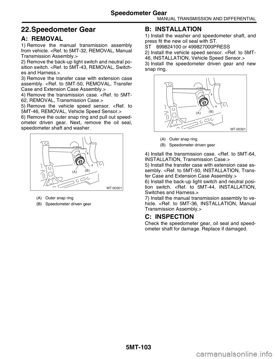
6) Remove the outer snap ring and pull out speed-
ometer driven gear. Next, remove the oil seal,
speedometer shaft and washer.
B: INSTALLATION
1) Install the washer and speedometer shaft, and
press fit the new oil seal with ST.
ST 899824100 or 499827000PRESS
2) Install the vehicle speed sensor.
3) Install the speedometer driven gear and new
snap ring.
4) Install the transmission case.
5) Install the transfer case with extension case as-
sembly.
6) Install the back-up light switch and neutral posi-
tion switch.
7) Install the manual transmission assembly to ve-
hicle.
C: INSPECTION
Check the speedometer gear, oil seal and speed-
ometer shaft for damage. Replace if damaged.
(A) Outer snap ring
(B) Speedometer driven gear
MT-00301
(A)(B)
(A) Outer snap ring
(B) Speedometer driven gear
MT-00301
(A)(B)
Page 2824 of 2870

5MT-111
MANUAL TRANSMISSION AND DIFFERENTIAL
General Diagnostic
26.General Diagnostic
A: INSPECTION
1. MANUAL TRANSMISSION
Symptom Possible cause Remedy
1. Gears are difficult to intermesh.
N
OTE:
The cause for difficulty in shifting gears
can be classified into two kinds: one is
malfunction of the gear shift system and
the other is malfunction of the transmis-
sion. However, if the operation is heavy
and engagement of the gears is difficult,
defective clutch disengagement may also
be responsible. Check whether the clutch
is correctly functioning, before checking
the gear shift system and transmission.(a) Worn, damaged or burred chamfer of
internal spline of sleeve and reverse
driven gearReplace.
(b) Worn, damaged or burred chamfer of
spline of gearsReplace.
(c) Worn or scratched bushings Replace.
(d) Incorrect contact between synchro-
nizer ring and gear cone or wear Correct or replace.
2. Gear slips out.
Gear slips out when coasting on rough
road.
Gear slips out during acceleration.(a) Defective pitching stopper adjustment Adjust.
(b) Loose engine mounting bolts Tighten or replace.
(c) Worn fork shifter, broken shifter fork
rail springReplace.
(d) Worn or damaged ball bearing Replace.
(e) Excessive clearance between splines
of synchronizer hub and synchronizer
sleeveReplace.
(f) Worn tooth step of synchronizer hub Replace.
(g) Worn 1st driven gear and driven shaft Replace.
(h) Worn 2nd driven gear and 2nd bush Replace.
(i) Worn reverse idler gear and bushing Replace.
3. Unusual noise comes from transmis-
sion.
N
OTE:
If an unusual noise is heard when the ve-
hicle is parked with its engine idling and if
the noise ceases when the clutch is disen-
gaged, it may be considered that the
noise comes from the transmission.(a) Insufficient or improper lubrication Lubricate or replace with specified oil.
(b) Worn or damaged gears and bearings
NOTE:
If the trouble is only wear of the tooth sur-
faces, merely a high roaring noise will oc-
cur at high speeds, but if any part is
broken, rhythmical knocking sound will be
heard even at low speeds.Replace.
Page 2825 of 2870

5MT-112
MANUAL TRANSMISSION AND DIFFERENTIAL
General Diagnostic
2. DIFFERENTIAL
Symptom Possible cause Remedy
1. Broken differential (case, gear, bear-
ing, etc.)
N
OTE:
Noise will develop and finally it will be-
come impossible to continue to run due to
broken pieces obstructing the gear revo-
lution. (a) Insufficient or improper oil Disassemble the differential and replace
broken components and at the same time
check other components for any trouble,
and replace if necessary.
(b) Use of vehicle under severe condi-
tions such as excessive load and
improper use of clutch Readjust the bearing preload and back-
lash and face contact of gears.
(c) Improper adjustment of taper roller
bearingAdjust.
(d) Improper adjustment of drive pinion
and hypoid driven gear Adjust.
(e) Excessive backlash due to worn dif-
ferential side gear, washer or differential
pinion vehicle under severe operating
conditions. Add recommended oil to specified level.
Do not use the vehicle under severe oper-
ating conditions.
(f) Loose hypoid driven gear clamping
boltsTighten.
2. Differential and hypoid gear noises
Troubles of the differential and hypoid
gear always appear as noise problems.
Therefore noise is the first indication of
the trouble. However noises from the
engine, muffler, tire, exhaust gas, bear-
ing, body, etc. are easily mistaken for the
differential noise. Pay special attention to
the hypoid gear noise because it is easily
confused with other gear noises. There
are the following four kinds of noises.
Gear noise when driving: If noise
increases as vehicle speed increases it
may be due to insufficient gear oil, incor-
rect gear engagement, damaged gears,
etc.
Gear noise when coasting: Damaged
gears due to maladjusted bearings and
incorrect shim adjustment
Bearing noise when driving or when
coasting: Cracked, broken or damaged
bearings
Noise which mainly occurs when turn-
ing: Unusual noise from differential side
gear, differential pinion, differential pinion
shaft, etc. (a) Insufficient oil Lubricate.
(b) Improper adjustment of hypoid driven
gear and drive pinionCheck tooth contact.
(c) Worn teeth of hypoid driven gear and
drive pinionReplace as a set.
Readjust the bearing preload.
(d) Loose roller bearing Readjust the hypoid driven gear to drive
pinion backlash and check tooth contact.
(e) Distorted hypoid driven gear or differ-
ential caseReplace.
(f) Worn washer and differential pinion
shaftReplace.