2004 SUBARU FORESTER transmission oil
[x] Cancel search: transmission oilPage 2767 of 2870
5MT-55
MANUAL TRANSMISSION AND DIFFERENTIAL
Transfer Drive Gear
E: INSPECTION
1) Bearings
Replace the bearings in the following cases:
Broken or rusty bearings
Worn or damaged
Bearings that fail to turn smoothly or make noise
when turned after gear oil lubrication.
2) Drive gear
Replace the drive gear in the following cases:
If their tooth surfaces and shaft are excessively
broken or damaged.
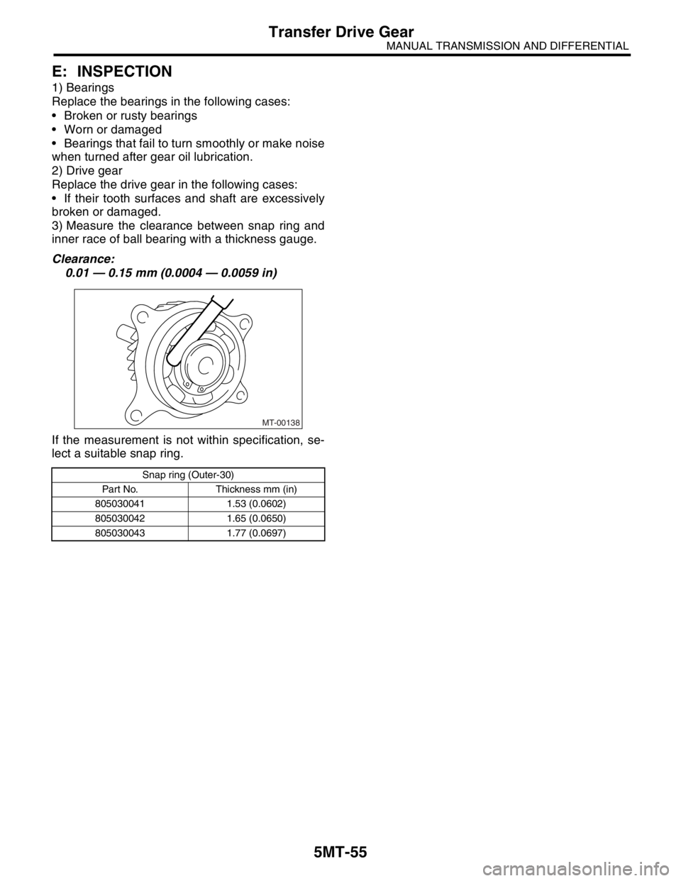
3) Measure the clearance between snap ring and
inner race of ball bearing with a thickness gauge.
Clearance:
0.01 — 0.15 mm (0.0004 — 0.0059 in)
If the measurement is not within specification, se-
lect a suitable snap ring.
Snap ring (Outer-30)
Part No. Thickness mm (in)
805030041 1.53 (0.0602)
805030042 1.65 (0.0650)
805030043 1.77 (0.0697)
MT-00138
Page 2770 of 2870
5MT-57
MANUAL TRANSMISSION AND DIFFERENTIAL
Transfer Driven Gear
C: DISASSEMBLY
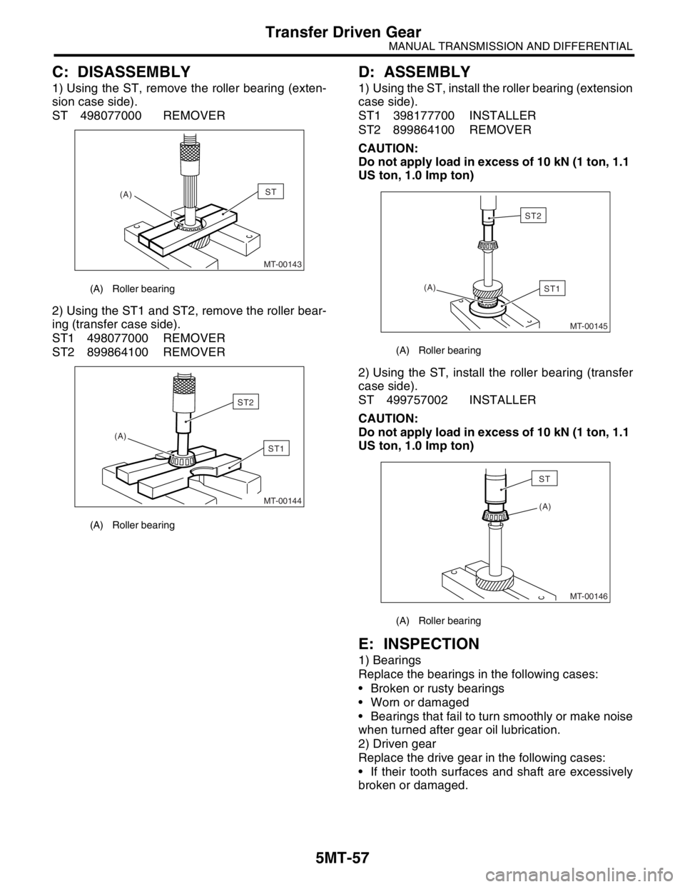
1) Using the ST, remove the roller bearing (exten-
sion case side).
ST 498077000 REMOVER
2) Using the ST1 and ST2, remove the roller bear-
ing (transfer case side).
ST1 498077000 REMOVER
ST2 899864100 REMOVER
D: ASSEMBLY
1) Using the ST, install the roller bearing (extension
case side).
ST1 398177700 INSTALLER
ST2 899864100 REMOVER
CAUTION:
Do not apply load in excess of 10 kN (1 ton, 1.1
US ton, 1.0 Imp ton)
2) Using the ST, install the roller bearing (transfer
case side).
ST 499757002 INSTALLER
CAUTION:
Do not apply load in excess of 10 kN (1 ton, 1.1
US ton, 1.0 Imp ton)
E: INSPECTION
1) Bearings
Replace the bearings in the following cases:
Broken or rusty bearings
Worn or damaged
Bearings that fail to turn smoothly or make noise
when turned after gear oil lubrication.
2) Driven gear
Replace the drive gear in the following cases:
If their tooth surfaces and shaft are excessively
broken or damaged.
(A) Roller bearing
(A) Roller bearing
MT-00143
(A)ST
MT-00144
(A)
ST1
ST2
(A) Roller bearing
(A) Roller bearing
MT-00145
(A)ST1
ST2
(A)
MT-00146
ST
Page 2771 of 2870
5MT-58
MANUAL TRANSMISSION AND DIFFERENTIAL
Center Differential
14.Center Differential
A: REMOVAL
1) Remove the manual transmission assembly
from vehicle.
2) Remove the transfer case with extension case
assembly.
3) Remove the extension case assembly.
Case Assembly.>
4) Remove the transfer driven gear.
5) Remove the center differential.
B: INSTALLATION
1) Install the center differential into transfer case.
2) Install the transfer driven gear.
3) Install the extension case assembly.
tension Case Assembly.>
4) Install the transfer case with extension case as-
sembly.
5) Install the back-up light switch and neutral posi-
tion switch.
6) Install the manual transmission assembly to ve-
hicle.
C: DISASSEMBLY
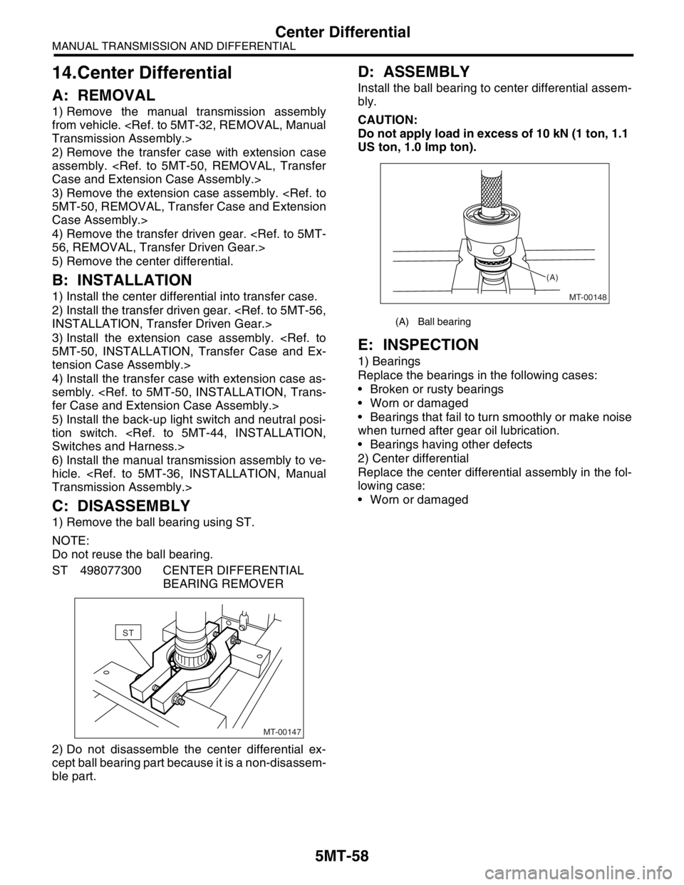
1) Remove the ball bearing using ST.
NOTE:
Do not reuse the ball bearing.
ST 498077300 CENTER DIFFERENTIAL
BEARING REMOVER
2) Do not disassemble the center differential ex-
cept ball bearing part because it is a non-disassem-
ble part.
D: ASSEMBLY
Install the ball bearing to center differential assem-
bly.
CAUTION:
Do not apply load in excess of 10 kN (1 ton, 1.1
US ton, 1.0 Imp ton).
E: INSPECTION
1) Bearings
Replace the bearings in the following cases:
Broken or rusty bearings
Worn or damaged
Bearings that fail to turn smoothly or make noise
when turned after gear oil lubrication.
Bearings having other defects
2) Center differential
Replace the center differential assembly in the fol-
lowing case:
Worn or damaged
MT-00147
ST
(A) Ball bearing
MT-00148 (A)
Page 2775 of 2870
5MT-62
MANUAL TRANSMISSION AND DIFFERENTIAL
Transmission Case
16.Transmission Case
A: REMOVAL
1. SINGLE-RANGE
1) Remove the manual transmission assembly
from vehicle.
2) Remove the clutch release lever.
3) Remove the transfer case with extension case
assembly.
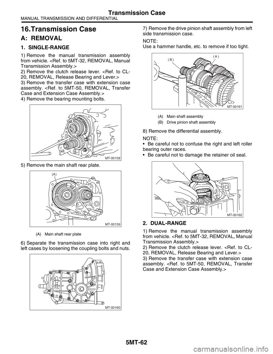
4) Remove the bearing mounting bolts.
5) Remove the main shaft rear plate.
6) Separate the transmission case into right and
left cases by loosening the coupling bolts and nuts.7) Remove the drive pinion shaft assembly from left
side transmission case.
NOTE:
Use a hammer handle, etc. to remove if too tight.
8) Remove the differential assembly.
NOTE:
Be careful not to confuse the right and left roller
bearing outer races.
Be careful not to damage the retainer oil seal.
2. DUAL-RANGE
1) Remove the manual transmission assembly
from vehicle.
2) Remove the clutch release lever.
3) Remove the transfer case with extension case
assembly.
MT-00158
MT-00159
(A)
MT-00160
(A) Main shaft assembly
(B) Drive pinion shaft assembly
MT-00161
(A)
(B)
MT-00162
Page 2777 of 2870
5MT-64
MANUAL TRANSMISSION AND DIFFERENTIAL
Transmission Case
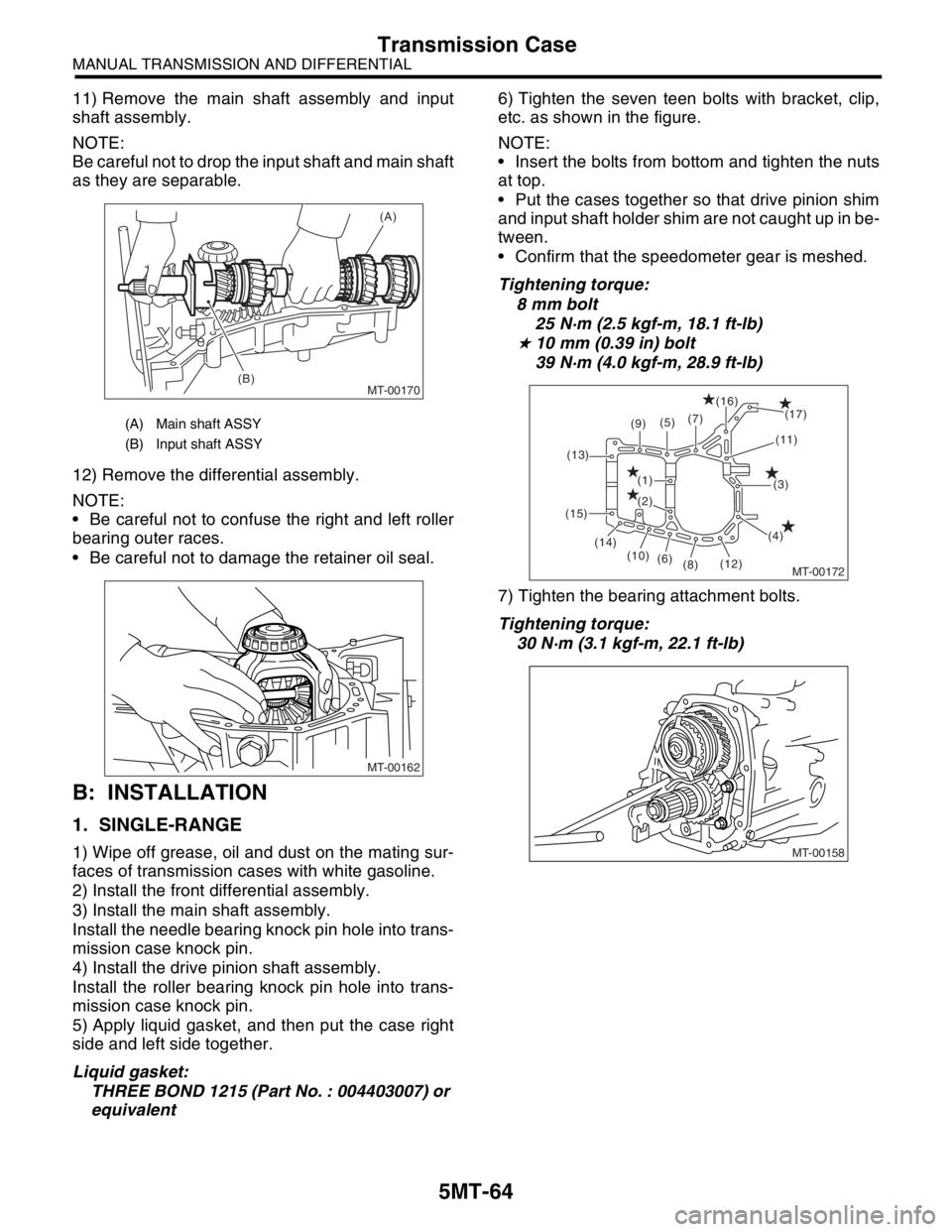
11) Remove the main shaft assembly and input
shaft assembly.
NOTE:
Be careful not to drop the input shaft and main shaft
as they are separable.
12) Remove the differential assembly.
NOTE:
Be careful not to confuse the right and left roller
bearing outer races.
Be careful not to damage the retainer oil seal.
B: INSTALLATION
1. SINGLE-RANGE
1) Wipe off grease, oil and dust on the mating sur-
faces of transmission cases with white gasoline.
2) Install the front differential assembly.
3) Install the main shaft assembly.
Install the needle bearing knock pin hole into trans-
mission case knock pin.
4) Install the drive pinion shaft assembly.
Install the roller bearing knock pin hole into trans-
mission case knock pin.
5) Apply liquid gasket, and then put the case right
side and left side together.
Liquid gasket:
THREE BOND 1215 (Part No. : 004403007) or
equivalent6) Tighten the seven teen bolts with bracket, clip,
etc. as shown in the figure.
NOTE:
Insert the bolts from bottom and tighten the nuts
at top.
Put the cases together so that drive pinion shim
and input shaft holder shim are not caught up in be-
tween.
Confirm that the speedometer gear is meshed.
Tightening torque:
8 mm bolt
25 N·m (2.5 kgf-m, 18.1 ft-lb)
★ 10 mm (0.39 in) bolt
39 N·m (4.0 kgf-m, 28.9 ft-lb)
7) Tighten the bearing attachment bolts.
Tightening torque:
30 N·m (3.1 kgf-m, 22.1 ft-lb)
(A) Main shaft ASSY
(B) Input shaft ASSY
MT-00170
(A)
(B)
MT-00162
(9)(7)
(5)
(1)
(2)(16)
(17)
(11)
(3)
(4)
(12)
(8) (6) (10) (14) (15)(13)
MT-00172
MT-00158
Page 2779 of 2870
5MT-66
MANUAL TRANSMISSION AND DIFFERENTIAL
Transmission Case
17) After checking the tooth contact of hypoid
gears, remove the lock plate. Then loosen the re-
tainer until the O-ring groove appears. Fit the O-
ring into groove and tighten the retainer into the po-
sition where retainer has been tightened in.
Tighten the lock plate.
NOTE:
Carry out this job on both upper and lower retain-
ers.
Tightening torque:
T: 25 N·m (2.5 kgf-m, 18.1 ft-lb)
18) Selecting of main shaft rear plate.
Single-Range.>
19) Install the clutch release lever and bearing.
20) Install the transfer case with extension case as-
sembly.
21) Install the manual transmission assembly into
the vehicle.
2. DUAL-RANGE
1) Wipe off grease, oil and dust on the mating sur-
faces of transmission cases with white gasoline.
2) Install the front differential assembly.
3) Install the main shaft assembly and input shaft
assembly.
Connect the main shaft assembly and input the
shaft assembly, and install needle bearing knock
pin hole into transmission case knock pin.
4) Install the drive pinion shaft assembly.
Install the roller bearing knock pin hole into trans-
mission case knock pin.
5) Apply liquid gasket, and then put the case right
side and left side together.
Liquid gasket:
THREE BOND 1215 (Parts No. 004403007) or
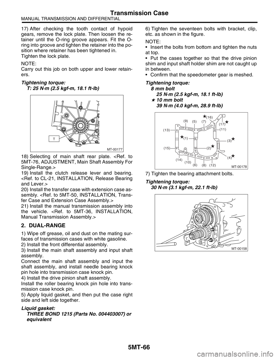
equivalent6) Tighten the seventeen bolts with bracket, clip,
etc. as shown in the figure.
NOTE:
Insert the bolts from bottom and tighten the nuts
at top.
Put the cases together so that the drive pinion
shim and input shaft holder shim are not caught up
in between.
Confirm that the speedometer gear is meshed.
Tightening torque:
8 mm bolt
25 N·m (2.5 kgf-m, 18.1 ft-lb)
★ 10 mm bolt
39 N·m (4.0 kgf-m, 28.9 ft-lb)
7) Tighten the bearing attachment bolts.
Tightening torque:
30 N·m (3.1 kgf-m, 22.1 ft-lb)
MT-00177
T
MT-00178
(9)
(7) (5)(16)
(17)
(11)
(3)
(4) (2) (1)
(12) (8) (6) (10) (14) (15) (13)
MT-00158
Page 2781 of 2870
5MT-68
MANUAL TRANSMISSION AND DIFFERENTIAL
Transmission Case
16) Turn the transmission main shaft several times
while tapping around the retainer lightly with plastic
hammer.
17) Inspect and adjust the backlash and tooth con-
tact of hypoid gear.
18) After checking the tooth contact of hypoid
gears, remove the lock plate. Then loosen the re-
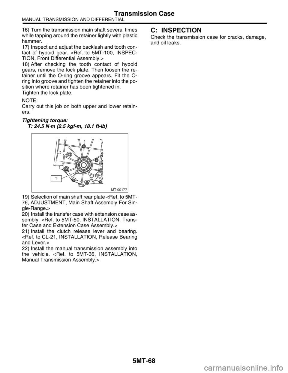
tainer until the O-ring groove appears. Fit the O-
ring into groove and tighten the retainer into the po-
sition where retainer has been tightened in.
Tighten the lock plate.
NOTE:
Carry out this job on both upper and lower retain-
ers.
Tightening torque:
T: 24.5 N·m (2.5 kgf-m, 18.1 ft-lb)
19) Selection of main shaft rear plate
gle-Range.>
20) Install the transfer case with extension case as-
sembly.
21) Install the clutch release lever and bearing.
22) Install the manual transmission assembly into
the vehicle.
Check the transmission case for cracks, damage,
and oil leaks.
MT-00177
T
Page 2782 of 2870
5MT-69
MANUAL TRANSMISSION AND DIFFERENTIAL
Main Shaft Assembly For Single-Range
17.Main Shaft Assembly For Sin-
gle-Range
A: REMOVAL
1) Remove the manual transmission assembly
from vehicle.
2) Remove the transfer case with extension case
assembly.
3) Remove the transmission case.
Assembly.>
4) Remove the drive pinion shaft assembly.
bly.>
5) Remove the main shaft assembly.
B: INSTALLATION
1) Wrap the clutch splined section with vinyl tape to
prevent damage to oil seal.
2) Apply grease Unilube #2 (or equivalent) to the
sealing lip of oil seal.
3) Install the needle bearing and new oil seal onto
the front of transmission main shaft assembly.
4) Install the needle bearing outer race knock pin
hole into transmission case knock pin.
NOTE:
Align the end face of seal with surface (A) when in-
stalling oil seal.
5) Install the drive pinion assembly.
bly.>
6) Install the transmission case.
7) Install the transfer case with extension case as-
sembly.
8) Install the manual transmission assembly to ve-
hicle.
C: DISASSEMBLY
1) Put vinyl tape around the main shaft splines to
protect oil seal from damage. Then pull out the oil
seal and needle bearing by hand.
2) Remove the lock nut from transmission main
shaft assembly.
NOTE:
Unlock the caulking before removing lock nut.
ST1 498937000 TRANSMISSION HOLDER
ST2 499987003 SOCKET WRENCH (35)
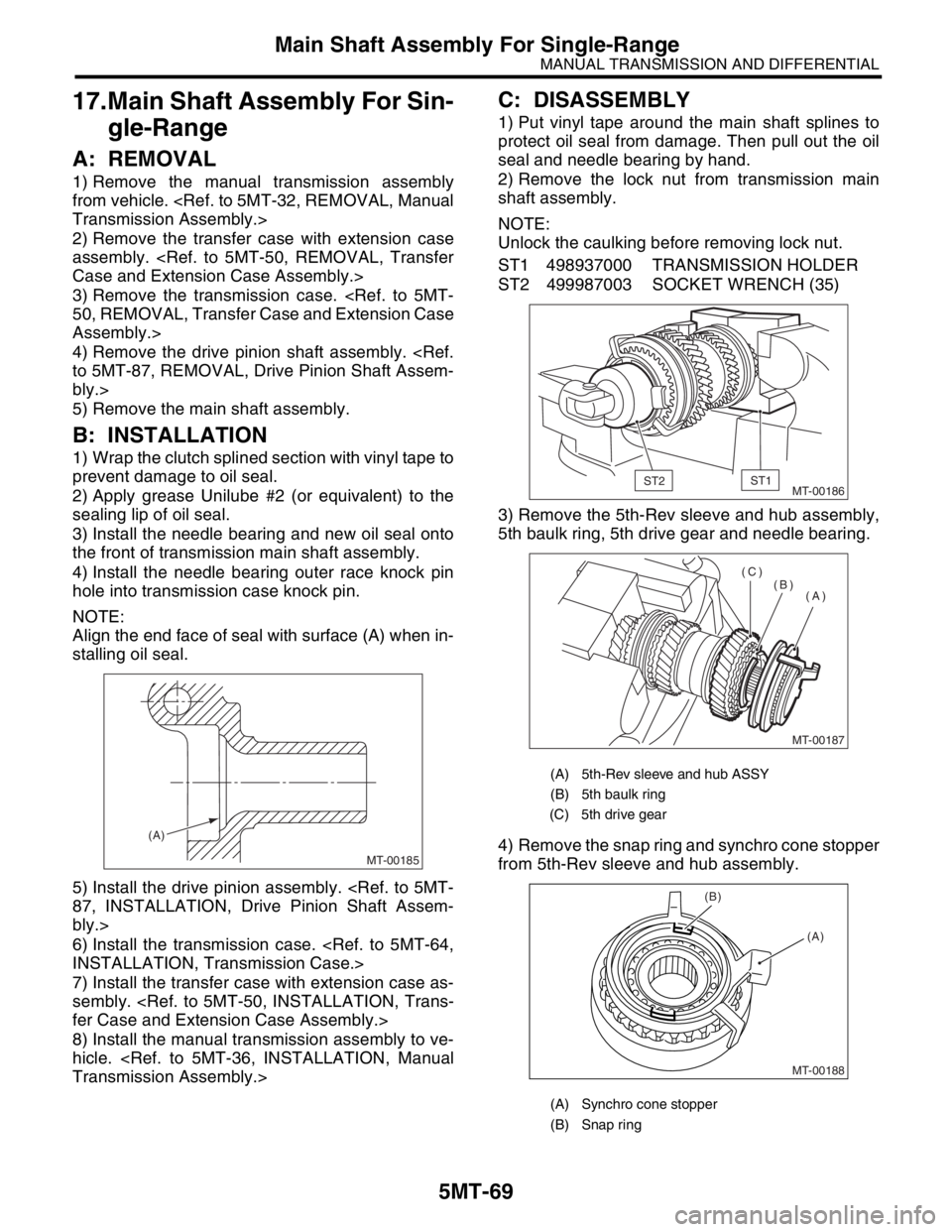
3) Remove the 5th-Rev sleeve and hub assembly,
5th baulk ring, 5th drive gear and needle bearing.
4) Remove the snap ring and synchro cone stopper
from 5th-Rev sleeve and hub assembly.
MT-00185
(A)
(A) 5th-Rev sleeve and hub ASSY
(B) 5th baulk ring
(C) 5th drive gear
(A) Synchro cone stopper
(B) Snap ring
MT-00186ST2ST1
MT-00187
(A) (B) (C)
MT-00188
(A) (B)