2004 SUBARU FORESTER display
[x] Cancel search: displayPage 2598 of 2870

4AT(H4DOTC)-22
AUTOMATIC TRANSMISSION (DIAGNOSTIC)
Power Indicator Light Display
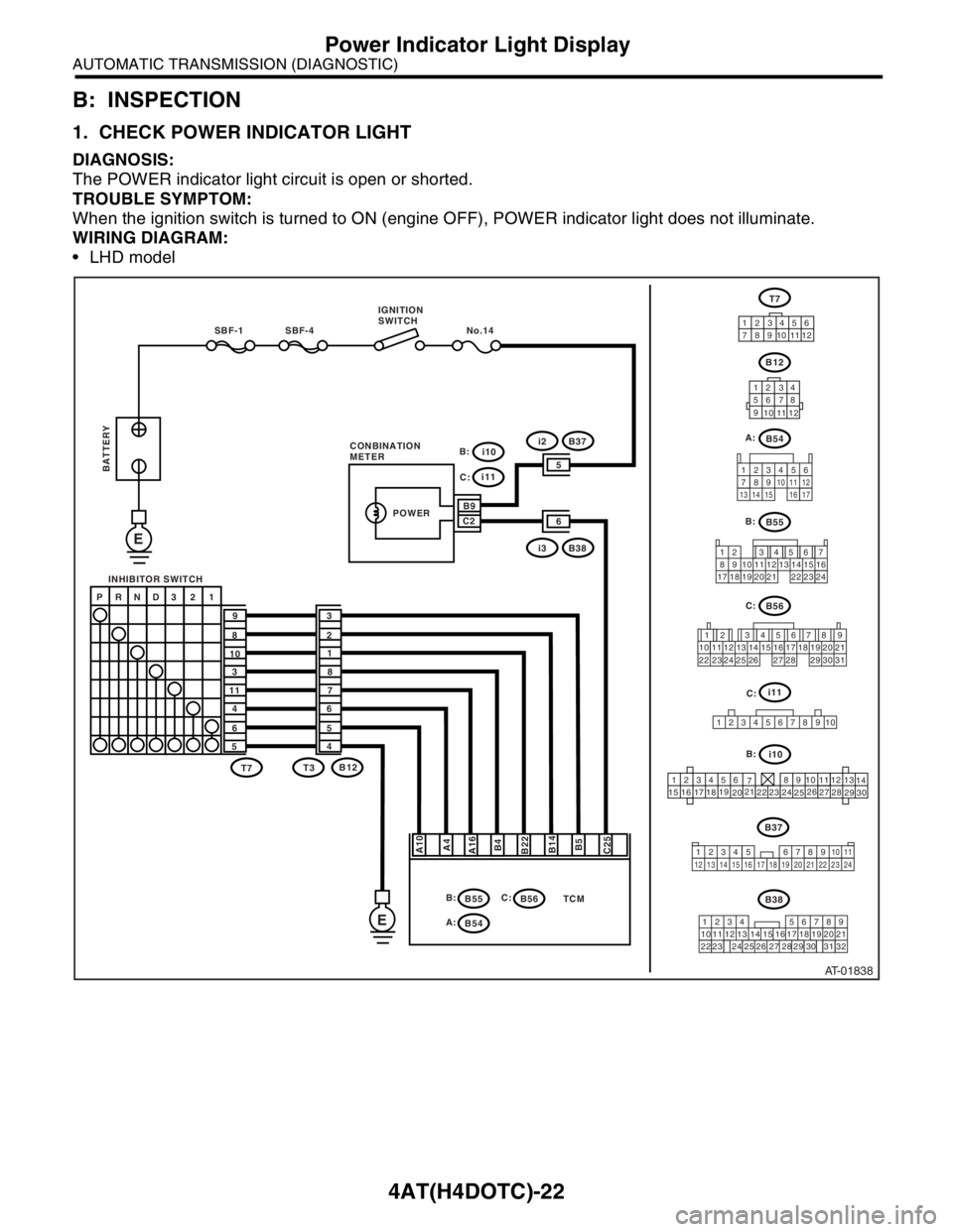
B: INSPECTION
1. CHECK POWER INDICATOR LIGHT
DIAGNOSIS:
The POWER indicator light circuit is open or shorted.
TROUBLE SYMPTOM:
When the ignition switch is turned to ON (engine OFF), POWER indicator light does not illuminate.
WIRING DIAGRAM:
LHD model
AT-01838
B55
B56
12 7
8956 34
10 11 12
19 20 2113 14 15 16
17 18 22 23 24
12 78 956 34
10 11 12 19 20 21
29 30 31 13 14 15 16 17
27 2818
22 23 24 25 26
TCM
SBF-4 No.14 SBF-1
E
E
A10
A4
A16
B4
B22
B5 B14
C25
P RND3 2 1
9
8
10
3
11
4
6
53
2
1
8
7
6
5
4
T7T7
B12
B55 T3B12
12 34
56 78
9
10
11
12
12 3456
789101112
123456
78 9 10 1112
13
14
15
1617
1819
2021
2223
24
2526
2728
29
30
i10
i11
B9
65
C2
i3B38
i2B37
POWER
B:
B54 A:
B56 C: B:
i10 B: C:
i11
C:
1234
5678910
C: B:
B54 A:
B38
219
32 1234 56
10 11 12 13 14 157
16
23 3019 20
22 26 27 28 298
17
24 3118
25
B37 IGNITION
SWITCH
INHIBITOR SWITCH
BATTERY
CONBINATION
METER
123
8910411 12
13 14 15 1656
7
17
34 12 8910 11
12 13 14 15 16 17 18 19 20 21 22 23 24567
Page 2599 of 2870

4AT(H4DOTC)-23
AUTOMATIC TRANSMISSION (DIAGNOSTIC)
Power Indicator Light Display
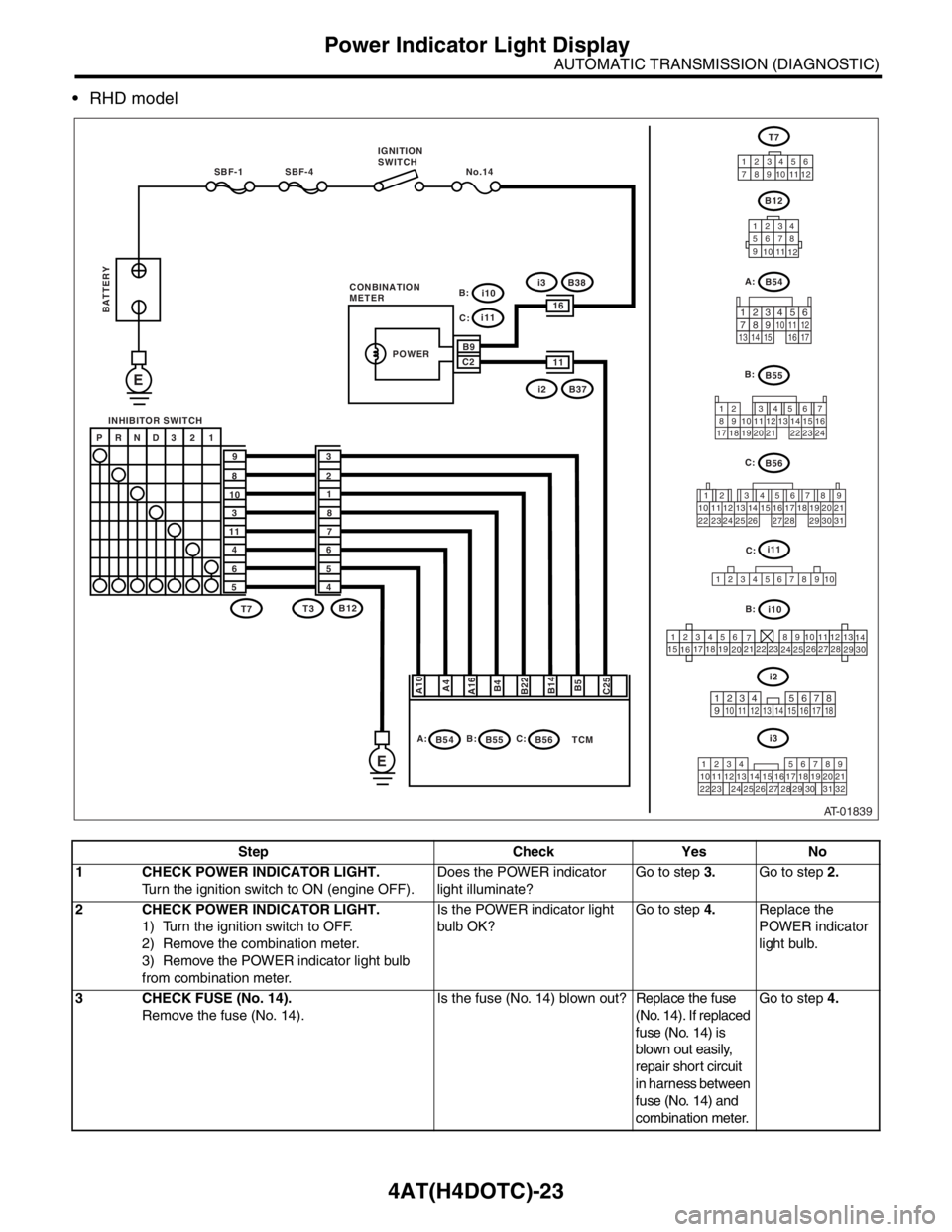
RHD model
Step Check Yes No
1 CHECK POWER INDICATOR LIGHT.
Turn the ignition switch to ON (engine OFF).Does the POWER indicator
light illuminate?Go to step 3.Go to step 2.
2 CHECK POWER INDICATOR LIGHT.
1) Turn the ignition switch to OFF.
2) Remove the combination meter.
3) Remove the POWER indicator light bulb
from combination meter.Is the POWER indicator light
bulb OK?Go to step 4.Replace the
POWER indicator
light bulb.
3 CHECK FUSE (No. 14).
Remove the fuse (No. 14).Is the fuse (No. 14) blown out? Replace the fuse
(No. 14). If replaced
fuse (No. 14) is
blown out easily,
repair short circuit
in harness between
fuse (No. 14) and
combination meter.Go to step 4.
AT-01839
TCM
SBF-4 No.14 SBF-1
E
E
A10
A4
A16
B4
B22
B5 B14
C25
P RND3 2 1
9
8
10
3
11
4
6
53
2
1
8
7
6
5
4
T7T7
B12
B55 T3B12
12 34
56 78
9
10
11
12
12 3456
789101112
i10
i11
B9
1116
C2
i2B37
i3B38
POWER
B:
B54 A:B56 C: B:
123456
78 9 10 1112
13
14
15
1617
1819
2021
2223
24
2526
2728
29
30
i10 B: C:
i11
C:
1234
5678910
B56
12 78 956 34
10 11 12 19 20 21
29 30 31 13 14 15 16 17
27 2818
22 23 24 25 26
C:
B55
12 7
8956 34
10 11 12
19 20 2113 14 15 16
17 18 22 23 24
B:
i3
219
32 1234 56
10 11 12 13 14 157
16
23 3019 20
22 26 27 28 298
17
24 3118
25
IGNITION
SWITCH
INHIBITOR SWITCH
BATTERY
CONBINATION
METERB54 A:
123
8910411 12
13 14 15 1656
7
17
i2
123 8
910411 12 13 14 15 165671718
Page 2600 of 2870

4AT(H4DOTC)-24
AUTOMATIC TRANSMISSION (DIAGNOSTIC)
Power Indicator Light Display
4 CHECK HARNESS CONNECTOR BETWEEN
COMBINATION METER AND IGNITION
SWITCH.
1) Turn the ignition switch to ON (engine OFF).
2) Measure the voltage between combination
meter connector and chassis ground.
Connector & terminal
(i10) No. 9 (+) — Chassis ground (
−):Is the voltage more than 9 V? Go to step 5.Repair the open
circuit in harness
between combina-
tion meter and bat-
tery.
5 CHECK COMBINATION METER.
Measure the voltage between combination
meter connector and chassis ground.
Connector & terminal
(i11) No. 2 (+) — Chassis ground (
−):Is the voltage less than 9 V? Repair the combi-
nation meter.
Meter Assembly.>Go to step 6.
6 CHECK OPEN CIRCUIT OF HARNESS.
1) Turn the ignition switch to OFF.
2) Disconnect the connector from combination
meter connector.
3) Measure the resistance of harness
between combination meter.
Connector & terminal
(B56) No. 25 — (i11) No. 2:Is the resistance less than 1
Ω?Go to step 7.Repair the open
circuit in harness
between TCM and
combination
meter, and poor
contact in cou-
pling connector.
7 CHECK INPUT SIGNAL FOR TCM.
1) Connect the connector to TCM and combi-
nation meter.
2) Turn the ignition switch to ON (engine OFF).
3) Measure the voltage between TCM con-
nector and chassis ground.
Connector & terminal
(B56) No. 25 (+) — Chassis ground (
−):Is the voltage less than 1 V? Go to step 8.Replace the TCM.
trol Module
(TCM).>
8 INSPECT POWER INDICATOR LIGHT.Does the POWER indicator
light illuminate?Diagnose accord-
ing to basic diag-
nostic procedure.Inspect power sup-
ply and ground cir-
cuit. Step Check Yes No
Page 2601 of 2870

4AT(H4DOTC)-25
AUTOMATIC TRANSMISSION (DIAGNOSTIC)
Power Indicator Light Display
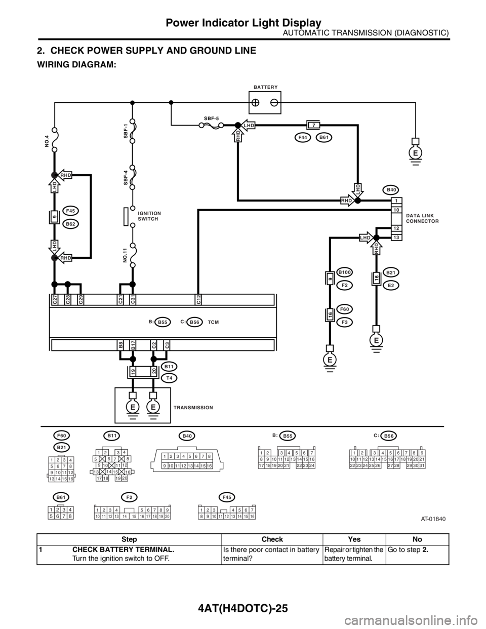
2. CHECK POWER SUPPLY AND GROUND LINE
WIRING DIAGRAM:
Step Check Yes No
1 CHECK BATTERY TERMINAL.
Turn the ignition switch to OFF.Is there poor contact in battery
terminal?Repair or tighten the
battery terminal.Go to step 2.
AT-01840
B40B55B56
B21
F2B61F45
F60
B55 B:B56
B11
T4TCM C:
B40
E
NO.11
NO.4
SBF-4 SBF-1 C27
C28C29
B8
B17C31C21
C12 C2
C3
12 345678
9101112
13 14 1516
1
12 10
13
SBF-5
B21
E216
E
B100
F29
F60
F316
F44B61 7
E
EE
123
4
5678
9101112
13 14 15 16
B11
1
234
56
78
9
1314
15
20
19 1716 10 1112
18
12 7
8956 34
10 11 12
19 20 2113 14 15 16
17 18 22 23 2412 78956 34
10 11 12 19 20 21
29 30 31 13 14 15 16 17
27 2818
22 23 24 25 26
19
20
BATTERY
IGNITION
SWITCH
TRANSMISSION
B:
C:DATA LINK
CONNECTOR
F45
B629
LHD
RHD
RHD
LHD
LHDRHD
LHD
RHDRHD
LHD
1234 5678910 11 12 13 14 15 16 17 18 19 201234567891011121314151612345678
Page 2602 of 2870

4AT(H4DOTC)-26
AUTOMATIC TRANSMISSION (DIAGNOSTIC)
Power Indicator Light Display
2 CHECK POWER SUPPLY OF TCM.
1) Disconnect the connector from TCM.
2) Turn the ignition switch to ON.
3) Measure the voltage between TCM con-
nector and chassis ground.
Connector & terminal
(B56) No. 27 (+) — Chassis ground (
−):
(B56) No. 28 (+) — Chassis ground (
−):
(B56) No. 29 (+) — Chassis ground (
−):Is the voltage 10 — 13 V? Go to step 4.Go to step 3.
3 CHECK FUSE (No. 4).
1) Turn the ignition switch to OFF.
2) Remove the fuse (No. 4).Is the fuse (No. 4) blown out? Replace the fuse
(No. 4). If replaced
fuse (No. 4) has
blown out easily,
repair short circuit
in harness between
fuse (No. 4) and
TCM.Repair the open
circuit in harness
between fuse (No.
4) and TCM, or
fuse (No. 4) and
battery, and poor
contact in cou-
pling connector.
4 CHECK IGNITION POWER SUPPLY CIR-
CUIT.
1) Turn the ignition switch to ON (engine OFF).
2) Measure the ignition power supply voltage
between TCM connector and chassis ground.
Connector & terminal
(B56) No. 21 (+) — Chassis ground (–):
(B56) No. 31 (+) — Chassis ground (–):Is the voltage 10 — 13 V? Go to step 6.Go to step 5.
5 CHECK FUSE (No. 11).
Remove the fuse (No. 11).Is the fuse (No. 11) blown out? Replace the fuse
(No. 11). If
replaced fuse (No.
11) has blown out
easily, repair short
circuit in harness
between fuse (No.
11) and TCM.Repair the open
circuit in harness
between fuse (No.
11) and TCM, or
fuse (No. 11) and
battery, and poor
contact in cou-
pling connector.
6 CHECK HARNESS CONNECTOR BETWEEN
TCM AND TRANSMISSION.
1) Turn the ignition switch to OFF.
2) Disconnect the connector from TCM and
transmission.
3) Measure the resistance of harness
between TCM and transmission connector.
Connector & terminal
(B55) No. 8 — (B11) No. 19:
(B55) No. 17 — (B11) No. 19:
(B56) No. 2 — (B11) No. 20:
(B56) No. 3 — (B11) No. 20:Is the resistance less than 1
Ω?Go to step 7.Repair the open
circuit in harness
between TCM,
transmission har-
ness connector,
and poor contact
in coupling con-
nector.
7 CHECK HARNESS CONNECTOR BETWEEN
TRANSMISSION AND TRANSMISSION
GROUND.
Measure the resistance of harness between
transmission and transmission ground.
Connector & terminal
(T4) No. 19 — Transmission ground:
(T4) No. 20 — Transmission ground:Is the resistance less than 1
Ω?Go to step 8.Repair the open
circuit in harness
between transmis-
sion and transmis-
sion ground.
8 CHECK POOR CONTACT IN CONNECTORS.Is there poor contact in TCM
power supply, ground line and
data link connector?Repair the con-
nector.Replace the TCM.
trol Module
(TCM).> Step Check Yes No
Page 2604 of 2870

4AT(H4DOTC)-28
AUTOMATIC TRANSMISSION (DIAGNOSTIC)
Diagnostic Procedure for Subaru Select Monitor Communication
Step Check Yes No
1 CHECK INSTALLATION OF TCM CONNEC-
TOR.
Turn the ignition switch to OFF.Is the TCM connector inserted
into TCM?Go to step 2.Insert the TCM
connector into
TCM.
2 CHECK SUBARU SELECT MONITOR POW-
ER SUPPLY CIRCUIT.
Measure the voltage between data link con-
nector and chassis ground.
Connector & terminal
(B40) No. 1 (+) — Chassis ground (
−):Is the voltage more than 10 V? Go to step 3.Repair the har-
ness and connec-
tor between battery
and data link con-
nector, and poor
contact in coupling
connector.
3 CHECK SUBARU SELECT MONITOR
GROUND CIRCUIT.
Measure the resistance of harness between
data link connector and chassis ground.
Connector & terminal
(B40) No. 12 — Chassis ground:
(B40) No. 13 — Chassis ground:Is the resistance less than 1
Ω?Go to step 4.Repair the open
circuit in harness
between data link
connector and
ground terminal,
and poor contact
in coupling con-
nector.
4 CHECK COMMUNICATION OF SUBARU SE-
LECT MONITOR.
1) Turn the ignition switch to ON.
2) Using the Subaru Select Monitor, check
whether communication to transmission sys-
tems can be executed normally.Are the contents of transmis-
sion system displayed on Sub-
aru Select Monitor?Go to step 9.Go to step 5.
5 CHECK COMMUNICATION OF SUBARU SE-
LECT MONITOR.
1) Turn the ignition switch to OFF.
2) Disconnect the TCM connector.
3) Check whether communication to engine
systems can be executed normally.Are the contents of engine sys-
tem displayed on Subaru
Select Monitor?Go to step 7.Go to step 6.
6 CHECK COMMUNICATION OF SUBARU SE-
LECT MONITOR.
1) Turn the ignition switch to OFF.
2) Connect the TCM connector.
3) Disconnect the ECM connector.
4) Check whether communication to transmis-
sion systems can be executed normally.Are the contents of transmis-
sion system displayed on Sub-
aru Select Monitor?Inspect the ECM. Go to step 7.
7 CHECK HARNESS CONNECTOR BETWEEN
EACH CONTROL MODULE AND DATA LINK
CONNECTOR.
1) Turn the ignition switch to OFF.
2) Disconnect the TCM and ECM connectors.
3) Measure the resistance between TCM con-
nector and chassis ground.
Connector & terminal
(B40) No. 10 — Chassis ground:Is the resistance more than 1
MΩ?Go to step 8.Repair the har-
ness and connec-
tor between each
control module and
data link connector.
8 CHECK OUTPUT SIGNAL FOR TCM.
1) Turn the ignition switch to ON.
2) Measure the voltage between TCM and
chassis ground.
Connector & terminal
(B40) No. 10 (+) — Chassis ground (
−):Is the voltage more than 1 V? Repair the harness
and connector
between each con-
trol module and
data link connector.Go to step 9.
9 CHECK HARNESS/CONNECTOR BETWEEN
TCM AND DATA LINK CONNECTOR.
Measure the resistance between TCM connec-
tor and data link connector.
Connector & terminal
(B56) No. 12 — (B40) No. 10:Is the resistance less than 0.5
Ω?Go to step 10.Repair the harness
and connector
between TCM and
data link connector.
Page 2610 of 2870

4AT(H4DOTC)-34
AUTOMATIC TRANSMISSION (DIAGNOSTIC)
Diagnostic Procedure with Diagnostic Trouble Code (DTC)
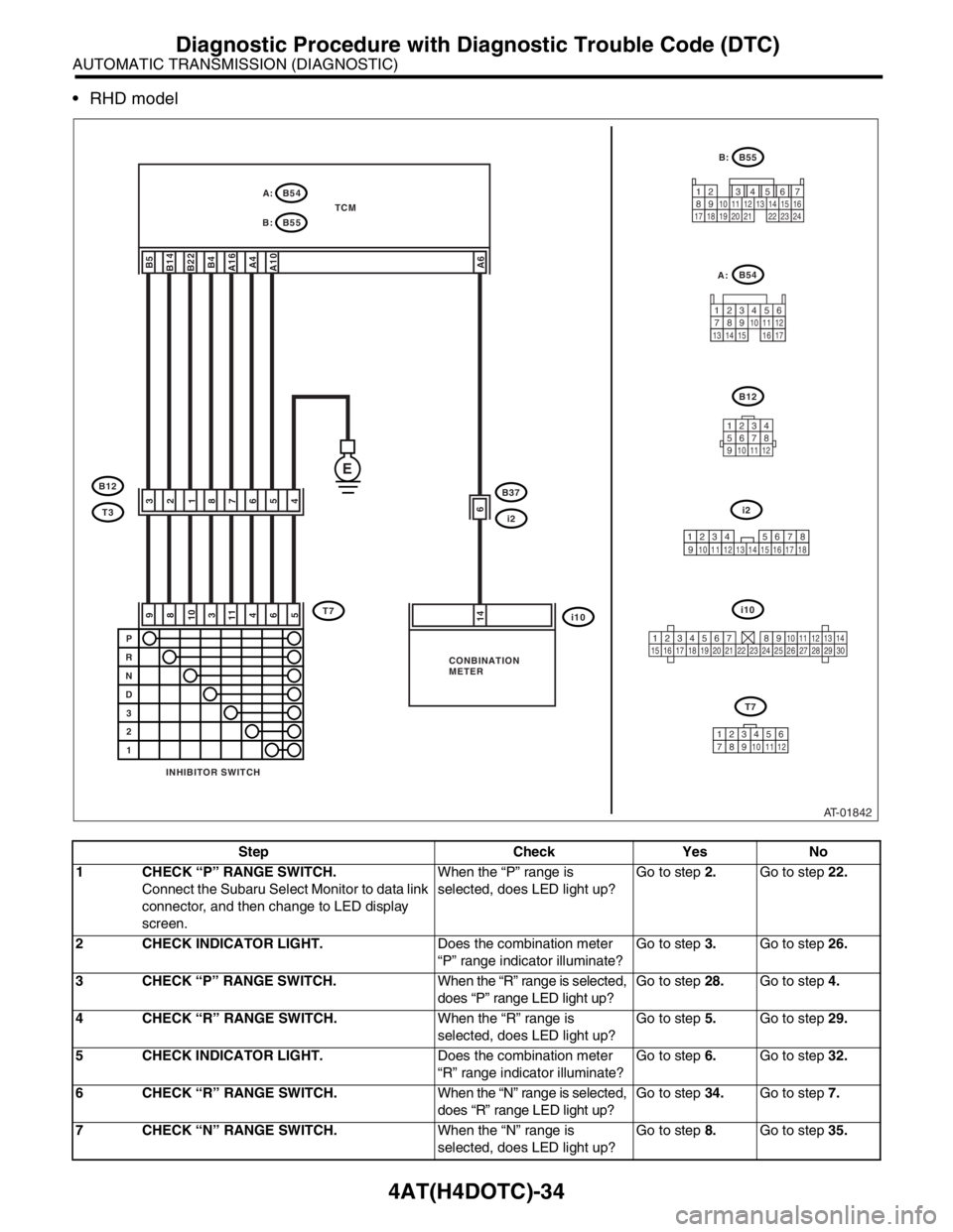
RHD model
Step Check Yes No
1 CHECK “P” RANGE SWITCH.
Connect the Subaru Select Monitor to data link
connector, and then change to LED display
screen.When the “P” range is
selected, does LED light up?Go to step 2.Go to step 22.
2 CHECK INDICATOR LIGHT.Does the combination meter
“P” range indicator illuminate?Go to step 3.Go to step 26.
3 CHECK “P” RANGE SWITCH.When the “R” range is selected,
does “P” range LED light up?Go to step 28.Go to step 4.
4 CHECK “R” RANGE SWITCH.When the “R” range is
selected, does LED light up?Go to step 5.Go to step 29.
5 CHECK INDICATOR LIGHT.Does the combination meter
“R” range indicator illuminate?Go to step 6.Go to step 32.
6 CHECK “R” RANGE SWITCH.When the “N” range is selected,
does “R” range LED light up?Go to step 34.Go to step 7.
7 CHECK “N” RANGE SWITCH.When the “N” range is
selected, does LED light up?Go to step 8.Go to step 35.
AT-01842
B5B14B22B4A16A4A10A6
32187654
9810311465
E
B37
i2
i10
B12
T3
T7
A:
B:B54
TCM
B55
6
14
P
R
N
D
3
2
1
B12
123456789101112
i10
123456789101112131415161718192021222324252627282930
1234567812 13 14 15 16 17 1891011
i2
B55
12 7
8956 34
10 11 12
19 20 2113 14 15 16
17 18 22 23 24
B:
INHIBITOR SWITCHCONBINATION
METERA:
B54
123
89
10411 12
13 14 15 1656
7
17
T7
123456
78910 11 12
Page 2636 of 2870

4AT(H4DOTC)-60
AUTOMATIC TRANSMISSION (DIAGNOSTIC)
Diagnostic Procedure with Diagnostic Trouble Code (DTC)
2 CHECK HARNESS CONNECTOR BETWEEN
TCM AND ECM.
Measure the resistance of harness between
TCM connector and chassis ground.
Connector & terminal
(B55) No. 13 — Chassis ground:Is the resistance more than 1
MΩ?Go to step 3.Repair the short
circuit in harness
between TCM and
ECM connector.
3 PREPARE SUBARU SELECT MONITOR.Do you have a Subaru Select
Monitor?Go to step 5.Go to step 4.
4 CHECK INPUT SIGNAL FOR TCM.
1) Connect the connectors to TCM and ECM.
2) Turn the ignition switch to ON (engine OFF).
3) Measure the voltage between TCM con-
nector and chassis ground.
Connector & terminal
(B55) No. 13 (+) — Chassis ground (
−):Is the voltage less than 1 V? Even if the POWER
indicator light was
blinking, the circuit
has returned to a
normal condition at
this time. A tempo-
rary poor contact of
the connector or
harness may be the
cause. Repair the
harness or connec-
tor of TCM and
ECM.Go to step 6.
5 CHECK INPUT SIGNAL FOR TCM USING
SUBARU SELECT MONITOR.
1) Connect the connectors to TCM and ECM.
2) Connect the Subaru Select Monitor to data
link connector.
3) Start the engine and turn Subaru Select
Monitor switch to ON.
4) Idle the engine.
5) Read the data of engine speed using Sub-
aru Select Monitor.
Display shows the engine speed signal value
sent from ECM.Is the revolution value same as
tachometer reading shown on
combination meter?Even if the POWER
indicator light was
blinking, the circuit
has returned to a
normal condition at
this time. A tempo-
rary poor contact of
the connector or
harness may be the
cause. Repair the
harness or connec-
tor of TCM and
ECM.Go to step 6.
6 CHECK POOR CONTACT.Is there poor contact in engine
speed signal circuit?Repair the poor
contact.Go to step 7.
7 CONFIRM DTC P0725.
Replace the ECM with a new one. Does the DTC appear again,
after memory has been
cleared?Replace the TCM.
trol Module
(TCM).>Replace the ECM.
Engine Control
Module (ECM).> Step Check Yes No