2004 SUBARU FORESTER radio
[x] Cancel search: radioPage 645 of 2870
IM-3
IMMOBILIZER (DIAGNOSTIC)
General Description
2. General Description
A: CAUTION
CAUTION:
The airbag system wiring harnesses rout-
ed near the immobilizer control module. All
airbag system wiring harness and connec-
tors are colored yellow. Do not use electrical
test equipment on these circuits.
Be careful not to damage the airbag system
wiring harness when servicing the immobilizer
control module.
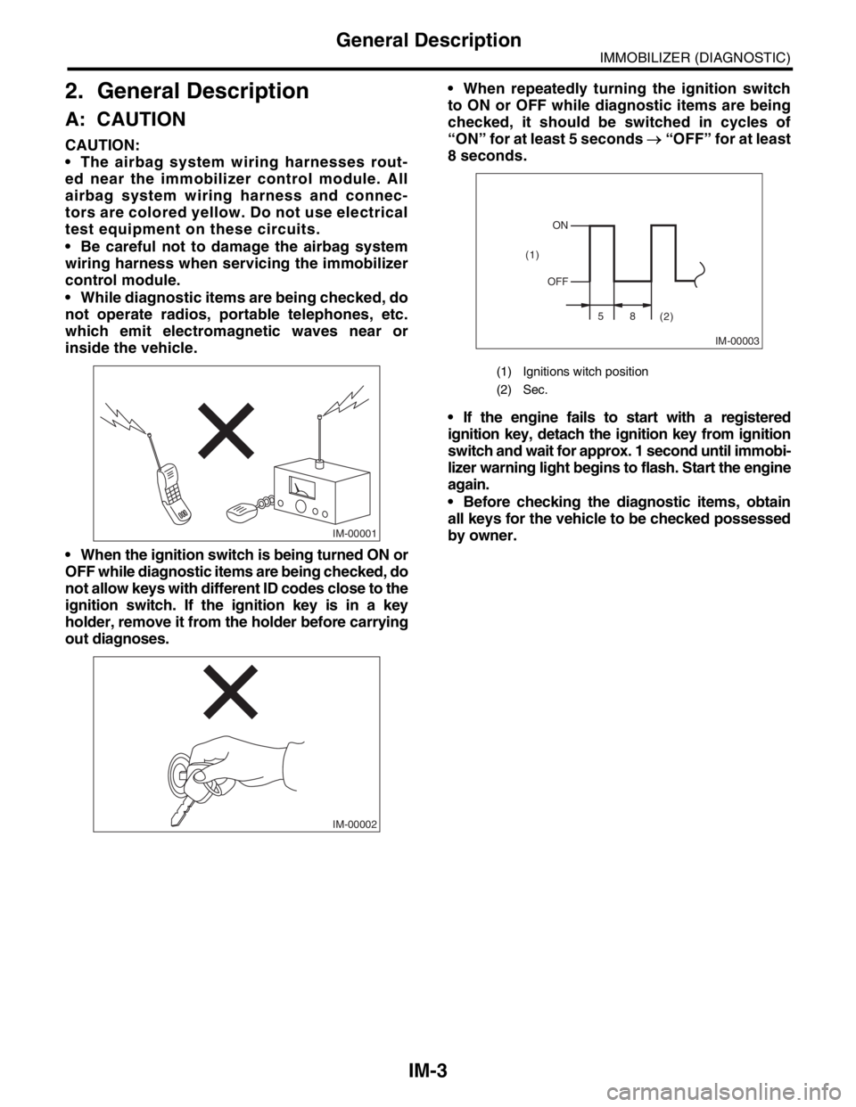
While diagnostic items are being checked, do
not operate radios, portable telephones, etc.
which emit electromagnetic waves near or
inside the vehicle.
When the ignition switch is being turned ON or
OFF while diagnostic items are being checked, do
not allow keys with different ID codes close to the
ignition switch. If the ignition key is in a key
holder, remove it from the holder before carrying
out diagnoses. When repeatedly turning the ignition switch
to ON or OFF while diagnostic items are being
checked, it should be switched in cycles of
“ON” for at least 5 seconds → “OFF” for at least
8 seconds.
If the engine fails to start with a registered
ignition key, detach the ignition key from ignition
switch and wait for approx. 1 second until immobi-
lizer warning light begins to flash. Start the engine
again.
Before checking the diagnostic items, obtain
all keys for the vehicle to be checked possessed
by owner.
IM-00001
IM-00002
(1) Ignitions witch position
(2) Sec.
IM-00003
ON
OFF
58
(2) (1)
Page 727 of 2870

PI-4
PRE-DELIVERY INSPECTION
Pre-delivery Inspection
Checks with the Engine Running
Dynamic Test with the Vehicle Running
Checks after Dynamic Test
Step Check point
26. Test mode connectors Test mode connectors
27. Starting condition Start the engine and check that the engine starts smoothly.
28. Exhaust system Check that the exhaust noise is normal and no leaks are found.
29. Indicator light Check that all the indicator lights operate normally.
30. Clock Check that the clock operates normally.
31. Radio Check that the radio system operates normally.
32. Front accessory power supply socket Check that the front accessory power supply socket operates normally.
33. Lighting system Check that the lighting systems operate normally.
34. Window washer Check that the window washer system operates normally.
35. Wiper Check that the wiper system operates normally.
36. Power window operation check Check the power window for correct operations.
Step Check point
37. Brake test Check that the foot brake operates normally.
38. Parking brake Check that the parking brake operates normally.
39. AT shift control Check the AT shift patterns are correct.
40. Heater & ventilation Check that the heater & ventilation system operates normally.
41. Air conditioner Check that the air conditioner operates normally.
42. Speed control Check that the speed control operates normally.
Step Check point
43. ATF level Check that the ATF level is normal.
44. Power steering fluid level Check that the power steering fluid level is normal.
45. Fluid leak check Check for fluid/oil leaks.
46. Water leak check Spray the vehicle with water and check for water leaks.
47. Appearance check 2 (1) Remove the protective coating (wrap guard).(if any)
(2) Check the body paints for damage and smears.
(3) Check the plated parts for damage and rust.
Page 734 of 2870
PI-11
PRE-DELIVERY INSPECTION
Pre-delivery Inspection
29.CLOCK
Check the clock for normal operations and enough
accuracy.
30.RADIO
Check the radio for full functionality and normal
noise level. Also check the CD unit operations.
31.FRONT ACCESSORY POWER SUPPLY
SOCKET
Check the front accessory power supply socket op-
erations.
32.LIGHTING SYSTEM
Check the headlight operations.
Check the brake light operations.
Check the other lights for normal operations.
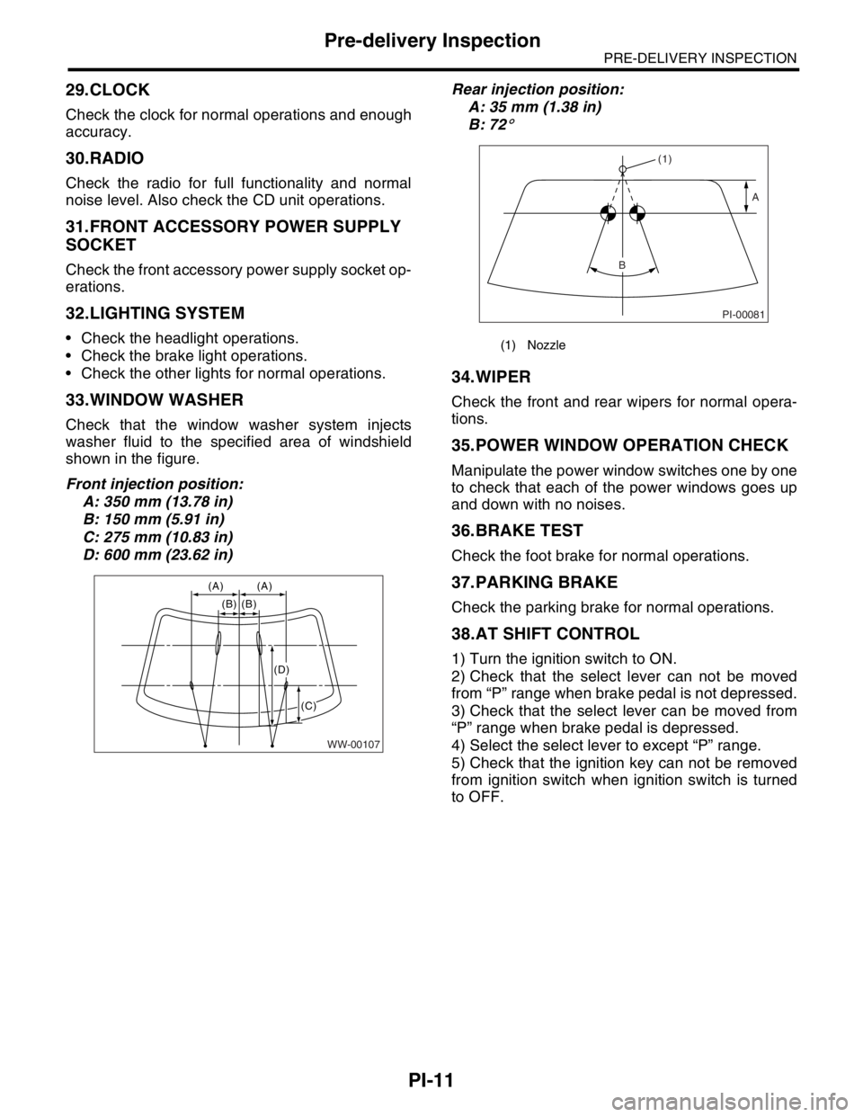
33.WINDOW WASHER
Check that the window washer system injects
washer fluid to the specified area of windshield
shown in the figure.
Front injection position:
A: 350 mm (13.78 in)
B: 150 mm (5.91 in)
C: 275 mm (10.83 in)
D: 600 mm (23.62 in)Rear injection position:
A: 35 mm (1.38 in)
B: 72
°
34.WIPER
Check the front and rear wipers for normal opera-
tions.
35.POWER WINDOW OPERATION CHECK
Manipulate the power window switches one by one
to check that each of the power windows goes up
and down with no noises.
36.BRAKE TEST
Check the foot brake for normal operations.
37.PARKING BRAKE
Check the parking brake for normal operations.
38.AT SHIFT CONTROL
1) Turn the ignition switch to ON.
2) Check that the select lever can not be moved
from “P” range when brake pedal is not depressed.
3) Check that the select lever can be moved from
“P” range when brake pedal is depressed.
4) Select the select lever to except “P” range.
5) Check that the ignition key can not be removed
from ignition switch when ignition switch is turned
to OFF.
WW-00107
(A) (A)
(B) (B)
(C)
(D)
(1) Nozzle
PI-00081
(1)
A
B
Page 1104 of 2870
EN(H4SO)-6
ENGINE (DIAGNOSTIC)
General Description
3. General Description
A: CAUTION
1) Airbag system wiring harness is routed near the
ECM, main relay and fuel pump relay.
CAUTION:
All air bag system wiring harnesses and con-
nectors are yellow. Do not use the electrical
test equipment on these circuits.
Be careful not to damage the Airbag system
wiring harness when servicing the ECM, TCM,
main relay and fuel pump relay.
2) Never connect the battery in reverse polarity.
The ECM will be destroyed immediately.
The fuel injector and other part will be damaged.
3) Do not disconnect the battery terminals while the
engine is running.
A large counter electromotive force will be generat-
ed in the generator, and this voltage may damage
electronic parts such as ECM, etc.
4) Before disconnecting the connectors of each
sensor and the ECM, be sure to turn the ignition
switch to OFF.
5) Poor contact has been identified as a primary
cause of this problem. Measure the voltage or re-
sistance of individual sensor or all electrical control
modules using a tapered pin with a diameter of less
than 0.64 mm (0.025 in). Do not insert the pin more
than 5 mm (0.20 in) into the part.
6) Remove the ECM from the located position after
disconnecting two cables on battery.
Otherwise, the ECM may be damaged.
CAUTION:
When replacing the ECM, be careful not to use
the wrong spec. ECM to avoid any damage on
the fuel injection system.
7) Connectors to each sensor in the engine com-
partment and the harness connectors on the en-
gine side and body side are all designed to be
waterproof. However, it is still necessary to take
care not to allow water to get into the connectors
when washing the vehicle, or when servicing the
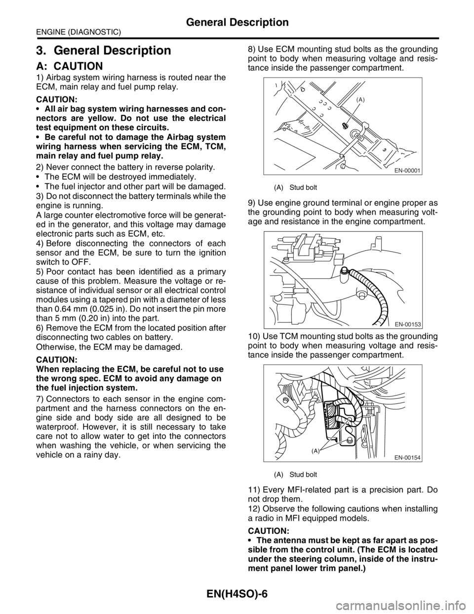
vehicle on a rainy day.8) Use ECM mounting stud bolts as the grounding
point to body when measuring voltage and resis-
tance inside the passenger compartment.
9) Use engine ground terminal or engine proper as
the grounding point to body when measuring volt-
age and resistance in the engine compartment.
10) Use TCM mounting stud bolts as the grounding
point to body when measuring voltage and resis-
tance inside the passenger compartment.
11) Every MFI-related part is a precision part. Do
not drop them.
12) Observe the following cautions when installing
a radio in MFI equipped models.
CAUTION:
The antenna must be kept as far apart as pos-
sible from the control unit. (The ECM is located
under the steering column, inside of the instru-
ment panel lower trim panel.)
(A) Stud bolt
(A) Stud bolt
EN-00001
(A)
EN-00153
EN-00154(A)
Page 1105 of 2870
EN(H4SO)-7
ENGINE (DIAGNOSTIC)
General Description
The antenna feeder must be placed as far
apart as possible from the ECM and MFI har-
ness.
Carefully adjust the antenna for correct
matching.
When mounting a large power type radio, pay
special attention to the three items above men-
tioned.
Incorrect installation of the radio may affect
the operation of the ECM.
13) Before disconnecting the fuel hose, disconnect
the fuel pump connector and crank the engine for
more than five seconds to release pressure in the
fuel system. If engine starts during this operation,
run it until it stops.
14) Problems in the electronic-controlled automatic
transmission may be caused by failure of the en-
gine, the electronic control system, the transmis-
sion proper, or by a combination of these. These
three causes must be distinguished clearly when
performing diagnostics.
15) Diagnostics should be conducted by rotating
with simple, easy operations and proceeding to
complicated, difficult operations. The most impor-
tant thing in diagnostics is to understand the cus-
tomer’s complaint, and distinguish between the
three causes.
16) In AT models, do not continue the stall for more
than five seconds. (from closed throttle, fully open
throttle to stall engine speed.)
17) On the model with ABS, when performing driv-
ing test in jacked-up or lifted-up position, some-
times the warning light may be lit, but this is not a
malfunction of the system. The reason for this is the
speed difference between the front and rear
wheels. After diagnosis of engine control system,
perform the ABS memory clearance procedure of
self-diagnosis function.
B: INSPECTION
Before performing diagnostics, check the following
items which might affect engine problems:
1. BATTERY
1) Measure battery voltage and specific gravity of
electrolyte.
Standard voltage: 12 V
Specific gravity: Above 1.260
2) Check the condition of the main and other fuses,
and harnesses and connectors. Also check for
proper grounding.
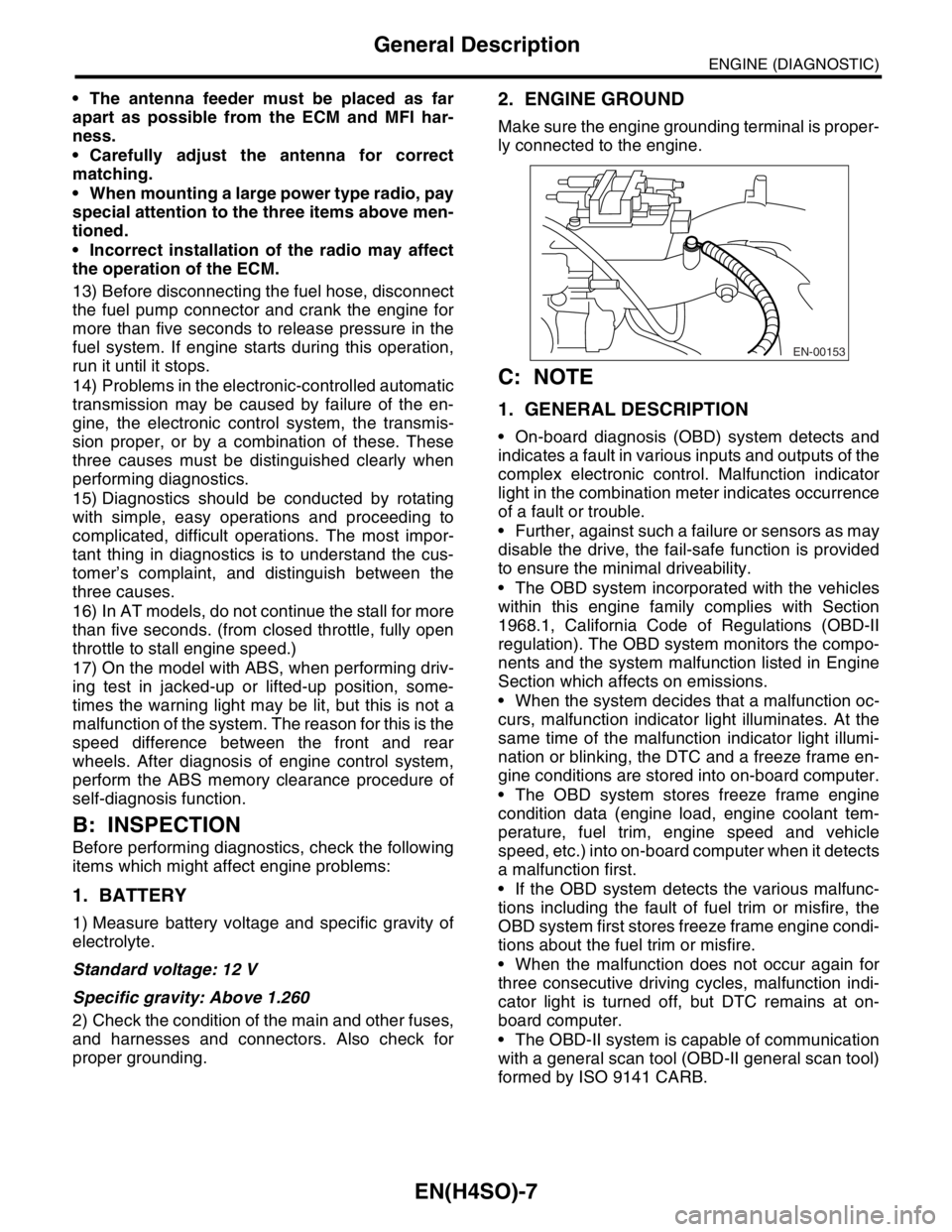
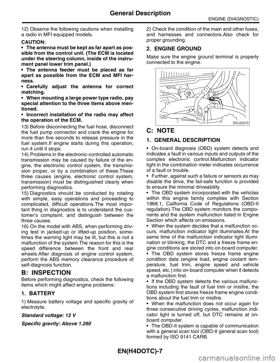
2. ENGINE GROUND
Make sure the engine grounding terminal is proper-
ly connected to the engine.
C: NOTE
1. GENERAL DESCRIPTION
On-board diagnosis (OBD) system detects and
indicates a fault in various inputs and outputs of the
complex electronic control. Malfunction indicator
light in the combination meter indicates occurrence
of a fault or trouble.
Further, against such a failure or sensors as may
disable the drive, the fail-safe function is provided
to ensure the minimal driveability.
The OBD system incorporated with the vehicles
within this engine family complies with Section
1968.1, California Code of Regulations (OBD-II
regulation). The OBD system monitors the compo-
nents and the system malfunction listed in Engine
Section which affects on emissions.
When the system decides that a malfunction oc-
curs, malfunction indicator light illuminates. At the
same time of the malfunction indicator light illumi-
nation or blinking, the DTC and a freeze frame en-
gine conditions are stored into on-board computer.
The OBD system stores freeze frame engine
condition data (engine load, engine coolant tem-
perature, fuel trim, engine speed and vehicle
speed, etc.) into on-board computer when it detects
a malfunction first.
If the OBD system detects the various malfunc-
tions including the fault of fuel trim or misfire, the
OBD system first stores freeze frame engine condi-
tions about the fuel trim or misfire.
When the malfunction does not occur again for
three consecutive driving cycles, malfunction indi-
cator light is turned off, but DTC remains at on-
board computer.
The OBD-II system is capable of communication
with a general scan tool (OBD-II general scan tool)
formed by ISO 9141 CARB.
EN-00153
Page 1634 of 2870

EN(H4DOTC)-4
ENGINE (DIAGNOSTIC)
Check List for Interview
2. Check List for Interview
A: INSPECTION
1. CHECK LIST NO. 1
Check the following items when problem has occurred.
NOTE:
Use copies of this page for interviewing customers.
Customer’s name Engine No.
Date of sale Fuel brand
Date of repair
Odometer readingkm
V.I.N.miles
Weather❏ Fine
❏ Cloudy
❏ Rainy
❏ Snowy
❏ Va r i o u s / O t h e r s :
Ambient air temperature°C (°F)
❏ Hot
❏ War m
❏ Cool
❏ Cold
Place❏ Highway
❏ Suburbs
❏ Inner city
❏ Uphill
❏ Downhill
❏ Rough road
❏ Others:
Engine temperature❏ Cold
❏ War ming-up
❏ After warming-up
❏ Any temperature
❏ Others:
Engine speed rpm
Vehicle speed km/h (MPH)
Driving conditions❏ Not affected
❏ At starting
❏ While idling
❏ At racing
❏ While accelerating
❏ While cruising
❏ While decelerating
❏ While turning (RH/LH)
Headlight❏ ON / ❏ OFF Rear defogger❏ ON / ❏ OFF
Blower❏ ON / ❏ OFF Radio❏ ON / ❏ OFF
A/C compressor❏ ON / ❏ OFF CD/Cassette❏ ON / ❏ OFF
Radiator fan❏ ON / ❏ OFF Car phone❏ ON / ❏ OFF
Fr o nt wi pe r❏ ON / ❏ OFF CB❏ ON / ❏ OFF
Rear Wiper❏ ON / ❏ OFF
Page 1637 of 2870
EN(H4DOTC)-7
ENGINE (DIAGNOSTIC)
General Description
12) Observe the following cautions when installing
a radio in MFI equipped models.
CAUTION:
The antenna must be kept as far apart as pos-
sible from the control unit. (The ECM is located
under the steering column, inside of the instru-
ment panel lower trim panel.)
The antenna feeder must be placed as far
apart as possible from the ECM and MFI har-
ness.
Carefully adjust the antenna for correct
matching.
When mounting a large power type radio, pay
special attention to the three items above men-
tioned.
Incorrect installation of the radio may affect
the operation of the ECM.
13) Before disconnecting the fuel hose, disconnect
the fuel pump connector and crank the engine for
more than five seconds to release pressure in the
fuel system.If engine starts during this operation,
run it until it stops.
14) Problems in the electronic-controlled automatic
transmission may be caused by failure of the en-
gine, the electronic control system, the transmis-
sion proper, or by a combination of these.These
three causes (engine, electronic control system,
transmission) must be distinguished clearly when
performing diagnostics.
15) Diagnostics should be conducted by rotating
with simple, easy operations and proceeding to
complicated, difficult operations.The most impor-
tant thing in diagnostics is to understand the cus-
tomer’s complaint, and distinguish between the
three causes.
16) On the model with ABS, when performing driv-
ing test in jacked-up or lifted-up position, some-
times the warning light may be lit, but this is not a
malfunction of the system.The reason for this is the
speed difference between the front and rear
wheels.After diagnosis of engine control system,
perform the ABS memory clearance procedure of
self-diagnosis function.
B: INSPECTION
Before performing diagnostics, check the following
items which might affect engine problems:
1. BATTERY
1) Measure battery voltage and specific gravity of
electrolyte.
Standard voltage: 12 V
Specific gravity: Above 1.2602) Check the condition of the main and other fuses,
and harnesses and connectors.Also check for
proper grounding.
2. ENGINE GROUND
Make sure the engine ground terminal is properly
connected to the engine.
C: NOTE
1. GENERAL DESCRIPTION
On-board diagnosis (OBD) system detects and
indicates a fault in various inputs and outputs of the
complex electronic control.Malfunction indicator
light in the combination meter indicates occurrence
of a fault or trouble.
Further, against such a failure or sensors as may
disable the drive, the fail-safe function is provided
to ensure the minimal driveability.
The OBD system incorporated with the vehicles
within this engine family complies with Section
1968.1, California Code of Regulations (OBD-II
regulation).The OBD system monitors the compo-
nents and the system malfunction listed in Engine
Section which affects on emissions.
When the system decides that a malfunction oc-
curs, malfunction indicator light illuminates.At the
same time of the malfunction indicator light illumi-
nation or blinking, the DTC and a freeze frame en-
gine conditions are stored into on-board computer.
The OBD system stores freeze frame engine
condition data (engine load, engine coolant tem-
perature, fuel trim, engine speed and vehicle
speed, etc.) into on-board computer when it detects
a malfunction first.
If the OBD system detects the various malfunc-
tions including the fault of fuel trim or misfire, the
OBD system first stores freeze frame engine condi-
tions about the fuel trim or misfire.
When the malfunction does not occur again for
three consecutive driving cycles, malfunction indi-
cator light is turned off, but DTC remains at on-
board computer.
The OBD-II system is capable of communication
with a general scan tool (OBD-II general scan tool)
formed by ISO 9141 CARB.
EN-00070
Page 2027 of 2870

EN(H4DOTC 2.5)-3
ENGINE (DIAGNOSTIC)
Check List for Interview
2. Check List for Interview
A: INSPECTION
1. CHECK LIST No. 1
Check the following items when problem has occurred.
NOTE:
Use copies of this page for interviewing customers.
Customer’s name Engine No.
Date of sale Fuel brand
Date of repair
Odometer readingkm
V.I.N.miles
Weather❏ Fine
❏ Cloudy
❏ Rainy
❏ Snowy
❏ Va r i o u s / O t h e r s :
Ambient air temperature°C (°F)
❏ Hot
❏ War m
❏ Cool
❏ Cold
Place❏ Highway
❏ Suburbs
❏ Inner city
❏ Uphill
❏ Downhill
❏ Rough road
❏ Others:
Engine temperature❏ Cold
❏ War ming-up
❏ After warming-up
❏ Any temperature
❏ Others:
Engine speed rpm
Vehicle speed km/h (MPH)
Driving conditions❏ Not affected
❏ At starting
❏ While idling
❏ At racing
❏ While accelerating
❏ While cruising
❏ While decelerating
❏ While turning (RH/LH)
Headlight❏ ON / ❏ OFF Rear defogger❏ ON / ❏ OFF
Blower❏ ON / ❏ OFF Radio❏ ON / ❏ OFF
A/C compressor❏ ON / ❏ OFF CD/Cassette❏ ON / ❏ OFF
Radiator fan❏ ON / ❏ OFF Car phone❏ ON / ❏ OFF
Fr o nt wi pe r❏ ON / ❏ OFF CB❏ ON / ❏ OFF
Rear Wiper❏ ON / ❏ OFF