Page 1018 of 2870
CO(H4SO)-35
COOLING
Radiator Main Fan and Fan Motor
8. Radiator Main Fan and Fan
Motor
A: REMOVAL
1. NON-TURBO MODEL
1) Set the vehicle on a lift.
2) Disconnect the ground cable from battery.
3) Lift-up the vehicle.
4) Remove the under cover.
5) Drain the coolant aprrox. 12 (1.06 US qt, 0.88
Imp qt).
ENGINE COOLANT, REPLACEMENT, Engine
Coolant.>
6) Disconnect the connector of main fan motor (A)
and sub fan motor (B).
7) Remove the ATF hose from two clips of radiator
fan motor assembly. (AT model)
8) Lower the vehicle.
9) Disconnect the over flow hose.
10) Remove the reservoir tank.11) Remove the radiator fan motor assembly
mounting bolts.
12) Disconnect the radiator inlet hose from engine.
13) Detach the power steering hose from clip on ra-
diator.
14) Rise up the radiator fan motor assembly to re-
move it from vehicle.
FU-00009
CO-00013
(A)(B)
CO-00015
CO-00064
CO-00035
CO-00037
CO-00065
Page 1019 of 2870
CO(H4SO)-36
COOLING
Radiator Main Fan and Fan Motor
2. TURBO MODEL
1) Set the vehicle on a lift.
2) Disconnect the ground cable from battery.
3) Remove the radiator upper bracket. (AT model)
4) Lift-up the vehicle.
5) Remove the under cover.
6) Drain the engine coolant approx. 12(1.06 US qt,
0.88 Imp qt).
OF ENGINE COOLANT, REPLACEMENT, Engine
Coolant.>
7) Disconnect the radiator main fan motor connec-
tor (A) and sub fan motor connector (B).8) Remove the radiator under cover securing bolt.
(AT model)
9) Pull the radiator lower hose upward to space ra-
diator from radiator under cover. Remove the ATF
hose to radiator fan motor assembly two clips. (AT
model)
10) Lower the vehicle.
11) Remove the V-belt cover.
12) Disconnect the overflow hose.
13) Remove the reservoir tank.
14) Remove the radiator main fan motor assembly
securing bolt.
FU-00009
CO-00036
CO-00013
(A)(B)
CO-00070
CO-00143
CO-00015
CO-00064
Page 1025 of 2870
CO(H4SO)-42
COOLING
Coolant Filler Tank
11.Coolant Filler Tank
A: REMOVAL
WARNING:
The radiator is pressurized. Wait until the en-
gine cools down before working on the radia-
tor.
1) Drain the coolant about 3.02 (3.2 US qt, 2.6 Imp
qt).
GINE COOLANT, REPLACEMENT, Engine Cool-
ant.>
2) Remove the air cleaner upper cover and air in-
take boot.
Cleaner.>
3) Remove the air cleaner element.
4) Disconnect the engine coolant hoses from cool-
ant filler tank.
5) Remove the bolts and nut which install coolant
filler tank.
6) Disconnect the engine coolant hose which con-
nects under side of coolant filler tank.
7) Remove the coolant filler tank.
B: INSTALLATION
1) Install in the reverse order of removal.
Tightening torque:
T1: 19 N
⋅m (1.9 kgf-m, 13.7 ft-lb)
T2: 21 N
⋅m (2.1 kgf-m, 15.2 ft-lb)
2) Fill engine coolant.
ING OF ENGINE COOLANT, REPLACEMENT,
Engine Coolant.>
CO-00051
CO-00052
T2
T1
CO-00053
Page 1033 of 2870

LU(H4SO)-5
LUBRICATION
General Description
C: CAUTION
Wear working clothing, including a cap, protec-
tive goggles, and protective shoes during opera-
tion.
Remove contamination including dirt and corro-
sion before removal, installation or disassembly.
Keep the disassembled parts in order and pro-
tect them from dust or dirt.
Before removal, installation or disassembly, be
sure to clarify the failure. Avoid unnecessary re-
moval, installation, disassembly, and replacement.
Be careful not to burn yourself, because each
part in the vehicle is hot after running.
Be sure to tighten fasteners including bolts and
nuts to the specified torque.
Place shop jacks or rigid racks at the specified
points.
Before disconnecting electrical connectors of
sensors or units, be sure to disconnect the ground
cable from battery.
(1) Plug (16) Oil pressure switch (33) O-ring
(2) Gasket (17) Oil filler cap (34) Oil filter connector (model without
oil cooler)
(3) Relief valve spring (18) O-ring
(4) Relief valve (19) Oil filler duct (35) Plug (model without oil cooler)
(5) Oil seal (20) O-ring (36) O-ring
(6) Oil pump case (21) Rocker cover
(7) Inner rotor (22) Oil strainerTightening torque: N
⋅m (kgf-m, ft-lb)
(8) Outer rotor (23) GasketT1: 5 (0.5, 3.6)
(9) Oil pump cover (24) Oil level gauge guideT2: 6.4 (0.65, 4.7)
(10) Oil filter (25) Oil panT3: 10 (1.0, 7.0)
(11) Oil cooler connector (model with
oil cooler)(26) Oil level gaugeT4: 44 (4.5, 32.5)
(27) Metal gasketT5: 69 (7.0, 50.9)
(12) Water by-pass pipe (model with oil
cooler)(28) Drain plugT6: 6.4 (0.65, 4.7)
(29) O-ringT7: 25 (2.5, 18.1)
(13) Oil cooler (model with oil cooler) (30) Adapter (1)T8: 44 (4.5, 32.5)
(14) O-ring (31) Adapter (2)T9: 54 (5.5, 40)
(15) Oil pump ASSY (32) Baffle plate
Page 1045 of 2870
LU(H4SO)-17
LUBRICATION
Oil Pan and Strainer
13) Drain the engine oil.
Set a container under the vehicle, and remove the
drain plug from oil pan.
14) Remove the front and center exhaust pipes.
(Non-turbo model)
AL, Front Exhaust Pipe.>
15) Remove the nuts which install front cushion
rubber onto front crossmember.
16) Remove the bolts which install oil pan on cylin-
der block while raising up engine.
17) Insert the oil pan cutter blade between the cyl-
inder block to oil pan clearance.
CAUTION:
Do not use a screwdriver or similar tool in place
of oil pan cutter.18) Remove the oil strainer.
19) Remove the baffle plate.
(A) Gasket
(B) Drain plug
LU-00029
(B)(A)
LU-00030
LU-00031
LU-00032
LU-00033
Page 1369 of 2870

FU(H4DOTC)-14
FUEL INJECTION (FUEL SYSTEM)
Intake Manifold
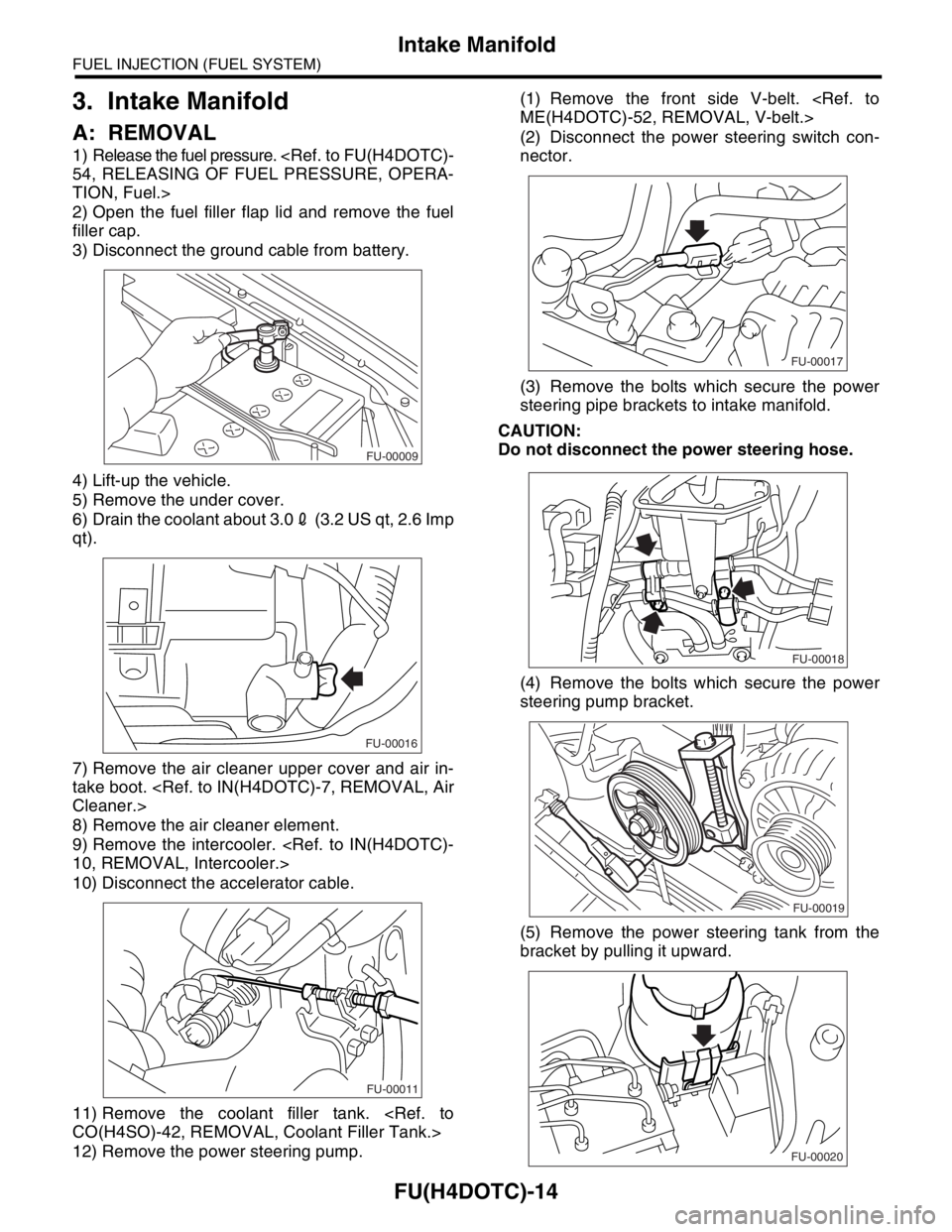
3. Intake Manifold
A: REMOVAL
1) Release the fuel pressure.
54, RELEASING OF FUEL PRESSURE, OPERA-
TION, Fuel.>
2) Open the fuel filler flap lid and remove the fuel
filler cap.
3) Disconnect the ground cable from battery.
4) Lift-up the vehicle.
5) Remove the under cover.
6) Drain the coolant about 3.02 (3.2 US qt, 2.6 Imp
qt).
7) Remove the air cleaner upper cover and air in-
take boot.
Cleaner.>
8) Remove the air cleaner element.
9) Remove the intercooler.
10, REMOVAL, Intercooler.>
10) Disconnect the accelerator cable.
11) Remove the coolant filler tank.
CO(H4SO)-42, REMOVAL, Coolant Filler Tank.>
12) Remove the power steering pump.(1) Remove the front side V-belt.
ME(H4DOTC)-52, REMOVAL, V-belt.>
(2) Disconnect the power steering switch con-
nector.
(3) Remove the bolts which secure the power
steering pipe brackets to intake manifold.
CAUTION:
Do not disconnect the power steering hose.
(4) Remove the bolts which secure the power
steering pump bracket.
(5) Remove the power steering tank from the
bracket by pulling it upward.
FU-00009
FU-00016
FU-00011
FU-00017
FU-00018
FU-00019
FU-00020
Page 1410 of 2870

FU(H4DOTC)-55
FUEL INJECTION (FUEL SYSTEM)
Fuel Tank
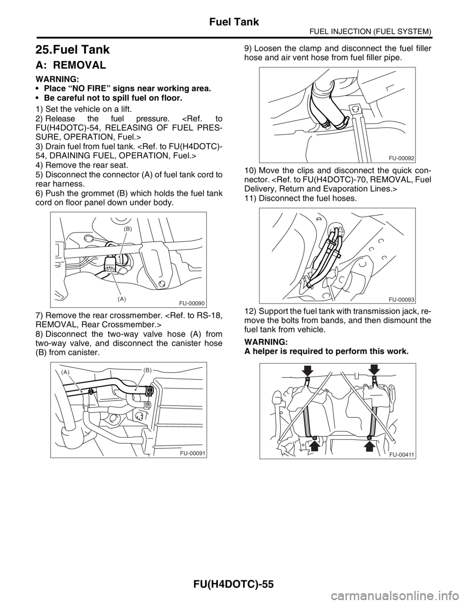
25.Fuel Tank
A: REMOVAL
WARNING:
Place “NO FIRE” signs near working area.
Be careful not to spill fuel on floor.
1) Set the vehicle on a lift.
2) Release the fuel pressure.
FU(H4DOTC)-54, RELEASING OF FUEL PRES-
SURE, OPERATION, Fuel.>
3) Drain fuel from fuel tank.
54, DRAINING FUEL, OPERATION, Fuel.>
4) Remove the rear seat.
5) Disconnect the connector (A) of fuel tank cord to
rear harness.
6) Push the grommet (B) which holds the fuel tank
cord on floor panel down under body.
7) Remove the rear crossmember.
REMOVAL, Rear Crossmember.>
8) Disconnect the two-way valve hose (A) from
two-way valve, and disconnect the canister hose
(B) from canister.9) Loosen the clamp and disconnect the fuel filler
hose and air vent hose from fuel filler pipe.
10) Move the clips and disconnect the quick con-
nector.
Delivery, Return and Evaporation Lines.>
11) Disconnect the fuel hoses.
12) Support the fuel tank with transmission jack, re-
move the bolts from bands, and then dismount the
fuel tank from vehicle.
WARNING:
A helper is required to perform this work.
(B)
(A)
FU-00090
(A)
(B)
FU-00091
FU-00092
FU-00093
FU-00411
Page 1420 of 2870
FU(H4DOTC)-65
FUEL INJECTION (FUEL SYSTEM)
Fuel Sub Level Sensor
29.Fuel Sub Level Sensor
A: REMOVAL
WARNING:
Place “NO FIRE” signs near working area.
Be careful not to spill fuel on floor.
1) Disconnect the ground cable from battery.
2) Lift-up the vehicle.
3) Drain fuel from fuel tank. Set a container under
vehicle and remove the drain plug from fuel tank.
4) Tighten the fuel drain plug.
Tightening torque:
26 N
⋅m (2.7 kgf-m, 19.2 ft-lb)
5) Remove the rear seat.6) Remove the service hole cover.
7) Disconnect the connector from fuel sub level
sensor.
8) Disconnect the fuel jet pump hose.
9) Remove the bolts which install the fuel sub level
sensor on fuel tank.
10) Remove the fuel sub level sensor.
FU-00009
FU-00089
FU-00089
FU-00113
FU-00114
FU-00115
FU-00116