Page 1543 of 2870
ME(H4DOTC)-83
MECHANICAL
Cylinder Block
20.Cylinder Block
A: REMOVAL
NOTE:
Before conducting this procedure, drain the engine
oil completely if applicable.
1) Remove the intake manifold.
FU(H4DOTC)-14, REMOVAL, Intake Manifold.> or
Manifold.>
2) Remove the V-belt.
REMOVAL, V-belt.>
3) Remove the crank pulley.
ME(H4DOTC)-55, REMOVAL, Crank Pulley.>
4) Remove the timing belt cover.
ME(H4DOTC)-57, REMOVAL, Timing Belt Cover.>
5) Remove the timing belt assembly.
ME(H4DOTC)-58, REMOVAL, Timing Belt Assem-
bly.>
6) Remove the cam sprocket.
ME(H4DOTC)-67, REMOVAL, Cam Sprocket.>
7) Remove the crank sprocket.
ME(H4DOTC)-68, REMOVAL, Crank Sprocket.>
8) Remove the generator and A/C compressor with
their brackets.
9) Remove the cylinder head assembly.
ME(H4DOTC)-76, REMOVAL, Cylinder Head As-
sembly.>
10) Remove the clutch disc and cover. (MT model)
er.>
11) Remove the flywheel. (MT model)
19, REMOVAL, Flywheel.>
12) Remove the drive plate. (AT model)
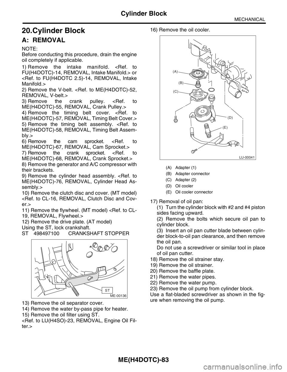
Using the ST, lock crankshaft.
ST 498497100 CRANKSHAFT STOPPER
13) Remove the oil separator cover.
14) Remove the water by-pass pipe for heater.
15) Remove the oil filter using ST.
ter.>16) Remove the oil cooler.
17) Removal of oil pan:
(1) Turn the cylinder block with #2 and #4 piston
sides facing upward.
(2) Remove the bolts which secure oil pan to
cylinder block.
(3) Insert an oil pan cutter blade between cylin-
der block-to-oil pan clearance, and then remove
the oil pan.
Do not use a screwdriver or similar tool in place
of oil pan cutter.
18) Remove the oil strainer stay.
19) Remove the oil strainer.
20) Remove the baffle plate.
21) Remove the water pipes.
22) Remove the water pump.
23) Remove the oil pump from cylinder block.
Use a flat-bladed screwdriver as shown in the fig-
ure when removing the oil pump.
ME-00136
ST
(A) Adapter (1)
(B) Adapter connector
(C) Adapter (2)
(D) Oil cooler
(E) Oil cooler connector
LU-00041
(A)
(B)
(C)
(D)
(E)
Page 1581 of 2870

ME(H4DOTC)-121
MECHANICAL
Engine Trouble in General
5. Engine does not return to
idle.Engine control system A
Intake system Loosened or cracked vacuum hose A
Others Stuck or damaged throttle valve A
Accelerator cable out of adjustment (2.0 L model) B
6. Dieseling (Run-on) Engine control system A
Cooling system Overheating B
Others Malfunction of evaporative emission control system B
7. Afterburning in exhaust
systemEngine control system A
Intake system Loosened or cracked intake duct C
Loosened or cracked PCV hose C
Loosened or cracked vacuum hose B
Defective PCV valve B
Loosened oil filler cap C
Belt Defective timing B
Compression Incorrect valve clearance B
Loosened spark plugs or defective gasket C
Loosened cylinder head bolts or defective gasket C
Improper valve seating B
Defective valve stem C
Worn or broken valve spring C
Worn or stuck piston rings, cylinder and piston C
Incorrect valve timing A
Lubrication system Incorrect oil pressure C
Cooling system Over cooling C
Others Malfunction of evaporative emission control system C
8. Knocking Engine control system A
Intake system Loosened oil filler cap B
Belt Defective timing B
Compression Incorrect valve clearance C
Incorrect valve timing B
Cooling system Overheating A
9. Excessive engine oil con-
sumptionIntake system Loosened or cracked PCV hose A
Defective PCV valve B
Loosened oil filler cap C
Compression Defective valve stem A
Worn or stuck piston rings, cylinder and piston A
Lubrication system Loosened oil pump attaching bolts and defective gas-
ketB
Defective oil filter o-ring B
Defective crankshaft oil seal B
Defective rocker cover gasket B
Loosened oil drain plug or defective gasket B
Loosened oil pan fitting bolts or defective oil pan B TROUBLE PROBLEM PARTS, ETC. POSSIBLE CAUSE RANK
Page 1944 of 2870
FU(H4DOTC 2.5)-14
FUEL INJECTION (FUEL SYSTEM)
Intake Manifold
3. Intake Manifold
A: REMOVAL
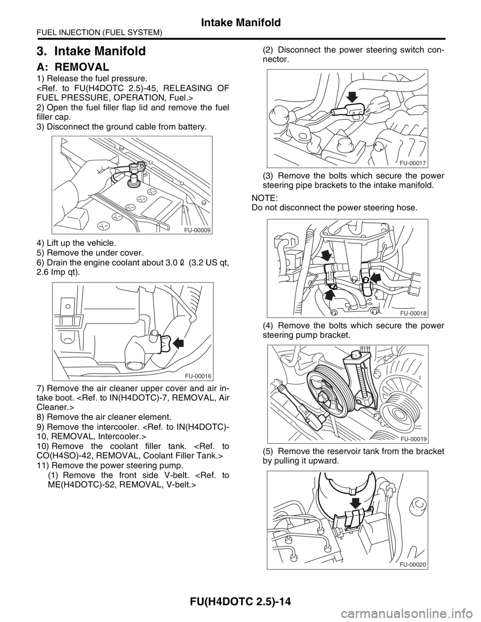
1) Release the fuel pressure.
FUEL PRESSURE, OPERATION, Fuel.>
2) Open the fuel filler flap lid and remove the fuel
filler cap.
3) Disconnect the ground cable from battery.
4) Lift up the vehicle.
5) Remove the under cover.
6) Drain the engine coolant about 3.02 (3.2 US qt,
2.6 Imp qt).
7) Remove the air cleaner upper cover and air in-
take boot.
Cleaner.>
8) Remove the air cleaner element.
9) Remove the intercooler.
10, REMOVAL, Intercooler.>
10) Remove the coolant filler tank.
CO(H4SO)-42, REMOVAL, Coolant Filler Tank.>
11) Remove the power steering pump.
(1) Remove the front side V-belt.
ME(H4DOTC)-52, REMOVAL, V-belt.>(2) Disconnect the power steering switch con-
nector.
(3) Remove the bolts which secure the power
steering pipe brackets to the intake manifold.
NOTE:
Do not disconnect the power steering hose.
(4) Remove the bolts which secure the power
steering pump bracket.
(5) Remove the reservoir tank from the bracket
by pulling it upward.
FU-00009
FU-00016
FU-00017
FU-00018
FU-00019
FU-00020
Page 1976 of 2870
FU(H4DOTC 2.5)-46
FUEL INJECTION (FUEL SYSTEM)
Fuel Tank
22.Fuel Tank
A: REMOVAL
WARNING:
Place “NO FIRE” signs near the working area.
Be careful not to spill fuel on the floor.
1) Set the vehicle on a lift.
2) Release the fuel pressure.
FUEL PRESSURE, OPERATION, Fuel.>
3) Drain fuel from the fuel tank.
OPERATION, Fuel.>
4) Remove the rear seat.
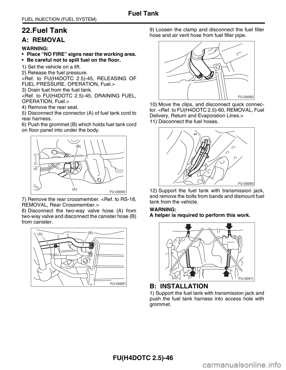
5) Disconnect the connector (A) of fuel tank cord to
rear harness.
6) Push the grommet (B) which holds fuel tank cord
on floor panel into under the body.
7) Remove the rear crossmember.
REMOVAL, Rear Crossmember.>
8) Disconnect the two-way valve hose (A) from
two-way valve and disconnect the canister hose (B)
from canister.9) Loosen the clamp and disconnect the fuel filler
hose and air vent hose from fuel filler pipe.
10) Move the clips, and disconnect quick connec-
tor.
Delivery, Return and Evaporation Lines.>
11) Disconnect the fuel hoses.
12) Support the fuel tank with transmission jack,
and remove the bolts from bands and dismount fuel
tank from the vehicle.
WARNING:
A helper is required to perform this work.
B: INSTALLATION
1) Support the fuel tank with transmission jack and
push the fuel tank harness into access hole with
grommet.
(B)
(A)
FU-00090
(A)
(B)
FU-00091
FU-00092
FU-00093
FU-00411
Page 1985 of 2870
FU(H4DOTC 2.5)-55
FUEL INJECTION (FUEL SYSTEM)
Fuel Sub Level Sensor
26.Fuel Sub Level Sensor
A: REMOVAL
WARNING:
Place “NO FIRE” signs near the working area.
Be careful not to spill fuel on the floor.
1) Disconnect the ground cable from battery.
2) Lift-up the vehicle.
3) Drain fuel from the fuel tank. Set a container un-
der the vehicle and remove the drain plug from fuel
tank.
4) Tighten the fuel drain plug.
Tightening torque:
26 N
⋅m (2.7 kgf-m, 19.2 ft-lb)
5) Remove the rear seat.6) Remove the service hole cover.
7) Disconnect the connector from fuel sub level
sensor.
8) Disconnect the fuel jet pump hose.
9) Remove the bolts which install fuel sub level
sensor on fuel tank.
10) Remove the fuel sub level sensor.
FU-00009
FU-00089
FU-00089
FU-00113
FU-00114
FU-00115
FU-00116
Page 2320 of 2870

4AT-8
AUTOMATIC TRANSMISSION
General Description
(1) ATF level gauge (19) Oil filter (41) Transmission case
(2) ATF charger pipe (20) Oil filter stud bolt (42) Plate ASSY
(3) O-ring (21) Drain plug (ATF) (43) Washer
(4) Transfer valve plate (22) Gasket (44) Bushing (turbo model)
(Non-turbo model) (23) Oil pan (45) ATF cooler inlet pipe (model with
ATF cooler (with warmer func-
tion)) (5) Transfer valve ASSY (24) Magnet
(Non-turbo model) (25) Stud bolt (Short)
(6) Transfer clutch seal
(Non-turbo model)(26) Stud bolt (Long) (46) ATF cooler outlet pipe (model
with ATF cooler (with warmer
function)) (27) Parking rod
(7) Transfer duty solenoid (non-turbo
model)(28) Manual plate
(29) Spring pin
(8) Straight pin (30) Detention springTightening torque: N
⋅m (kgf-m, ft-lb)
(9) Return spring (31) BallT1: 3.4 (0.35, 2.6)
(10) Shaft (32) SpringT2: 5 (0.5, 3.6)
(11) Parking pawl (33) GasketT3: 6 (0.6, 4.4)
(12) Parking support (34) ATF cooler outlet pipe (model
without ATF cooler (with warmer
function))T4: 8 (0.8, 6)
(13) Inlet filter (Non-turbo model)T5: 12 (1.2, 8.7)
(14) GasketT6: 13 (1.3, 10)
(15) ATF cooler inlet pipe (model with-
out ATF cooler (with warmer func-
tion))(35) Union screwT7: 14 (1.4, 10)
(36) Oil sealT8: 18 (1.8, 13)
(37) Range select leverT9: 25 (2.5, 18.1)
(16) Union screw (38) Inhibitor switch ASSYT10: 45 (4.6, 33.2)
(17) O-ring (39) NippleT11: 21 (2.1, 15.5)
(18) Test plug (40) Air breather hose
Page 2353 of 2870
4AT-41
AUTOMATIC TRANSMISSION
Automatic Transmission Assembly
20) Lift-up the vehicle.
21) Remove the under cover.
22) Remove the front, center, rear, exhaust pipes
and muffler. (Non-turbo model).
Pipe.>
Exhaust Pipe.>
AL, Muffler.>
23) Remove the center, rear exhaust pipe and muf-
fler. (Turbo model)
haust Pipe.>
AL, Rear Exhaust Pipe.>
16, REMOVAL, Muffler.>
24) Remove the heat shield cover. (If equipped)
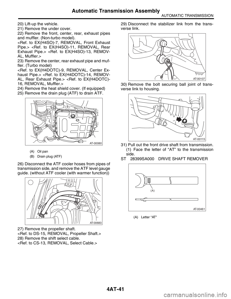
25) Remove the drain plug (ATF) to drain ATF.
26) Disconnect the ATF cooler hoses from pipes of
transmission side, and remove the ATF level gauge
guide. (without ATF cooler (with warmer function))
27) Remove the propeller shaft.
28) Remove the shift select cable.
29) Disconnect the stabilizer link from the trans-
verse link.
30) Remove the bolt securing ball joint of trans-
verse link to housing.
31) Pull out the front drive shaft from transmission.
(1) Face the letter of “AT” to the transmission
side.
ST 28399SA000 DRIVE SHAFT REMOVER
(A) Oil pan
(B) Drain plug (ATF)
AT-00080
(A)(B)
AT-00683
(A) Letter “AT”
AT-00107
AT-00115
AT-00461
(A)
Page 2368 of 2870
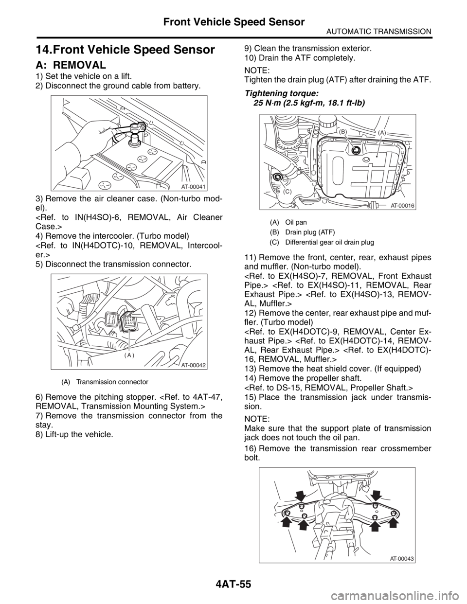
4AT-55
AUTOMATIC TRANSMISSION
Front Vehicle Speed Sensor
14.Front Vehicle Speed Sensor
A: REMOVAL
1) Set the vehicle on a lift.
2) Disconnect the ground cable from battery.
3) Remove the air cleaner case. (Non-turbo mod-
el).
Case.>
4) Remove the intercooler. (Turbo model)
er.>
5) Disconnect the transmission connector.
6) Remove the pitching stopper.
REMOVAL, Transmission Mounting System.>
7) Remove the transmission connector from the
stay.
8) Lift-up the vehicle.9) Clean the transmission exterior.
10) Drain the ATF completely.
NOTE:
Tighten the drain plug (ATF) after draining the ATF.
Tightening torque:
25 N
⋅m (2.5 kgf-m, 18.1 ft-lb)
11) Remove the front, center, rear, exhaust pipes
and muffler. (Non-turbo model).
Pipe.>
Exhaust Pipe.>
AL, Muffler.>
12) Remove the center, rear exhaust pipe and muf-
fler. (Turbo model)
haust Pipe.>
AL, Rear Exhaust Pipe.>
16, REMOVAL, Muffler.>
13) Remove the heat shield cover. (If equipped)
14) Remove the propeller shaft.
15) Place the transmission jack under transmis-
sion.
NOTE:
Make sure that the support plate of transmission
jack does not touch the oil pan.
16) Remove the transmission rear crossmember
bolt.
(A) Transmission connector
AT-00041
AT-00042
(A)
(A) Oil pan
(B) Drain plug (ATF)
(C) Differential gear oil drain plug
AT-00016
(A) (B)
(C)
AT-00043