2004 SUBARU FORESTER cruise
[x] Cancel search: cruisePage 2475 of 2870

4AT(H4SO)-16
AUTOMATIC TRANSMISSION (DIAGNOSTIC)
Transmission Control Module (TCM) I/O Signal
(1) Transmission control module
(TCM)(17) “P” range indicator light (35) Torque control signal 2
(18) “P” range switch (36) Torque control signal 1
(2) Cruise control module (19) “R” range indicator light (37) Intake manifold pressure signal
(3) ABS control module (20) “R” range switch (38) AT diagnostics signal
(4) Ignition switch (21) “N” range indicator light (39) Engine control module (ECM)
(5) Brake switch (22) “N” range switch (40) ATF temperature sensor
(6) Brake light (23) “D” range indicator light (41) Torque converter turbine speed
sensor
(7) Battery (24) “D” range switch
(8) Combination meter (Speedome-
ter circuit)(25) “3” range indicator light (42) Rear vehicle speed sensor
(26) “3” range switch (43) Front vehicle speed sensor
(9) AT OIL TEMP warning light (27) “2” range indicator light (44) Shift solenoid 1
(10) FWD indicator light (28) “2” range switch (45) Shift solenoid 2
(11) POWER indicator light (29) “1” range indicator light (46) 2-4 brake timing solenoid
(12) FWD switch (30) “1” range switch (47) Line pressure duty solenoid
(13) POWER switch (31) Data link connector (48) 2-4 brake duty solenoid
(14) Kick-down switch (32) Throttle position sensor (49) Lock-up duty solenoid
(15) Hold indicator light (33) Engine speed signal (50) Low clutch timing solenoid
(16) HOLD switch (34) Torque control cut signal (51) Transfer duty solenoid
Page 2477 of 2870
![SUBARU FORESTER 2004 Service Repair Manual 4AT(H4SO)-18
AUTOMATIC TRANSMISSION (DIAGNOSTIC)
Subaru Select Monitor
2. READ CURRENT DATA
1) On the «Main Menu» display screen, select the {Each System Check} and press the [YES] key.
2) On the « SUBARU FORESTER 2004 Service Repair Manual 4AT(H4SO)-18
AUTOMATIC TRANSMISSION (DIAGNOSTIC)
Subaru Select Monitor
2. READ CURRENT DATA
1) On the «Main Menu» display screen, select the {Each System Check} and press the [YES] key.
2) On the «](/manual-img/17/57426/w960_57426-2476.png)
4AT(H4SO)-18
AUTOMATIC TRANSMISSION (DIAGNOSTIC)
Subaru Select Monitor
2. READ CURRENT DATA
1) On the «Main Menu» display screen, select the {Each System Check} and press the [YES] key.
2) On the «System Selection Menu» display screen, select the {Transmission Control System} and press the
[YES] key.
3) Press the [YES] key after the information of transmission type is displayed.
4) On the «Transmission Diagnosis» display screen, select the {Current Data Display & Save} and press the
[YES] key.
5) On the «Data Display Menu» display screen, select the {Data Display} and press the [YES] key.
6) Using the scroll key, move the display screen up or down until desired data is shown.
A list of the support data is shown in the following table.
NOTE:
For detailed operation procedure, refer to the SUBARU SELECT MONITOR OPERATION MANUAL.
Contents Display Unit of measure
Battery voltage Battery Voltage V
Rear vehicle speed sensor signal Rear Wheel Speed km/h or MPH
Front vehicle speed sensor signal Front Wheel Speed km/h or MPH
Engine speed signal Engine Speed rpm
Automatic transmission fluid temperature signal ATF Temp.°C or °F
Throttle position signal Throttle Sensor Voltage V
Gear position Gear Position —
Line pressure control duty ratio Line Pressure Duty Ratio %
Lock up clutch control duty ratio Lock Up Duty Ratio %
Transfer clutch control duty ratio (AWD model) Transfer Duty Ratio %
Power supply for throttle position sensor Throttle Sensor Power V
Torque converter turbine speed signal Turbine Revolution Speed rpm
2-4 brake timing pressure control duty ratio Brake Clutch Duty Ratio %
Intake manifold pressure sensor voltage Mani. Pressure Voltage V
FWD switch signal FWD Switch ON or OFF
Stop light switch signal Stop Light Switch ON or OFF
Anti lock brake system signal ABS Signal ON or OFF
Cruise control system signal Cruise Control Signal ON or OFF
Parking range signal P Range Signal ON or OFF
Neutral range signal N Range Signal ON or OFF
Reverse range signal R Range Signal ON or OFF
Drive range signal D Range Signal ON or OFF
3rd range signal 3rd Range Signal ON or OFF
2nd range signal 2nd Range Signal ON or OFF
1st range signal 1st Range Signal ON or OFF
Shift control solenoid A Shift Solenoid #1 ON or OFF
Shift control solenoid B Shift Solenoid #2 ON or OFF
Torque control output signal #1 Torque Control Signal 1 ON or OFF
Torque control output signal #2 Torque Control Signal 2 ON or OFF
Torque control cut signal Torque Control Cut Sig. ON or OFF
2-4 brake timing control solenoid valve 2-4 Brake Timing Sol. ON or OFF
Low clutch timing control solenoid valve Low Clutch Timing Sol. ON or OFF
Automatic transmission diagnosis indicator lamp Diagnosis Lamp ON or OFF
Power mode switch signal Power Mode Switch ON or OFF
Hold mode switch signal Hold Mode Switch ON or OFF
Kick down switch signal Kick Down Switch ON or OFF
Automatic transmission fluid temperature lamp ATF Temperature Lamp ON or OFF
Page 2547 of 2870

4AT(H4SO)-88
AUTOMATIC TRANSMISSION (DIAGNOSTIC)
Diagnostic Procedure without Diagnostic Trouble Code (DTC)
B: CHECK BRAKE SWITCH
C: CHECK ABS SWITCH
D: CHECK CRUISE CONTROL SWITCH
Step Check Yes No
1 CHECK BRAKE SWITCH.When the brake pedal is
depressed, does LED light up?Go to step CHECK
ABS SWITCH.
CHECK CRUISE
CONTROL
SWITCH, Diag-
nostic Procedure
without Diagnostic
Trouble Code
(DTC).>Check the brake
switch circuit.
DTC P0703
TORQUE CON-
VERTER/BRAKE
SWITCH “B” CIR-
CUIT, Diagnostic
Procedure with
Diagnostic Trou-
ble Code (DTC).>
Step Check Yes No
1 CHECK ABS SWITCH.Does the LED of ABS switch
light up?Check the ABS
switch circuit.
CONTROL (NON
CONTROLLED),
Diagnostics Proce-
dure with Diagnos-
tic Trouble Code
(DTC).>
ABS-AT CON-
TROL (CON-
TROLLED),
Diagnostics Proce-
dure with Diagnos-
tic Trouble Code
(DTC).>Go to step CHECK
CRUISE CON-
TROL SWITCH.
CHECK CRUISE
CONTROL
SWITCH, Diag-
nostic Procedure
without Diagnostic
Trouble Code
(DTC).>
Step Check Yes No
1 CHECK CRUISE CONTROL SWITCH.When the cruise control is set,
does LED light up?Go to step CHECK
KICK-DOWN
SWITCH.
CHECK KICK–
DOWN SWITCH,
Diagnostic Proce-
dure without Diag-
nostic Trouble
Code (DTC).>Check the cruise
control.
Diagnostic Proce-
dure with Diagnos-
tic Trouble Code
(DTC).>
Page 2592 of 2870

4AT(H4DOTC)-16
AUTOMATIC TRANSMISSION (DIAGNOSTIC)
Subaru Select Monitor
6) Using the scroll key, move the display screen up or down until desired data is shown.
A list of the support data is shown in the following table.
NOTE:
For detailed operation procedure, refer to the “SUBARU SELECT MONITOR OPERATION MANUAL”.
Contents Display Unit of measure
Battery voltage Battery Voltage V
Rear vehicle speed sensor signal Rear Wheel Speed km/h or MPH
Front vehicle speed sensor signal Front Wheel Speed km/h or MPH
Engine speed signal Engine Speed rpm
ATF temperature signal ATF Temp.°C or °F
Throttle position signal Throttle Sensor Voltage V
Gear position Gear Position —
Line pressure control duty ratio Line Pressure Duty Ratio %
Lock up clutch control duty ratio Lock Up Duty Ratio %
Transfer clutch control duty ratio Transfer Duty Ratio %
Power supply for throttle position sensor Throttle Sensor Power V
Torque converter turbine speed signal Turbine Revolution Speed rpm
2-4 brake timing pressure control duty ratio Brake Clutch Duty Ratio %
Low clutch duty ratio L/C Duty %
High clutch duty ratio H/C Duty %
Low & reverse brake duty ratio L&R/B Duty %
Throttle position Throttle position %
Accelerator pedal position Accel. Opening Angle %
Cruise control system Cruise Control Signal ON or OFF
Automatic transmission fluid temperature lamp ATF Temperature Lamp ON or OFF
Stop light switch signal Stop Light Switch ON or OFF
ABS signal ABS Signal ON or OFF
Parking range signal P Range Signal ON or OFF
Neutral range signal N Range Signal ON or OFF
Reverse range signal R Range Signal ON or OFF
Drive range signal D Range Signal ON or OFF
3rd range signal 3rd Range Signal ON or OFF
2nd range signal 2nd Range Signal ON or OFF
1st range signal 1st Range Signal ON or OFF
AT diagnosis indicator lamp Diagnosis Lamp ON or OFF
POWER switch signal POWER Switch ON or OFF
HOLD switch signal HOLD Switch ON or OFF
FWD switch signal FWD SW ON or OFF
Shift lock solenoid signal Shift Lock solenoid ON or OFF
Page 2838 of 2870

CL-12
CLUTCH SYSTEM
General Description
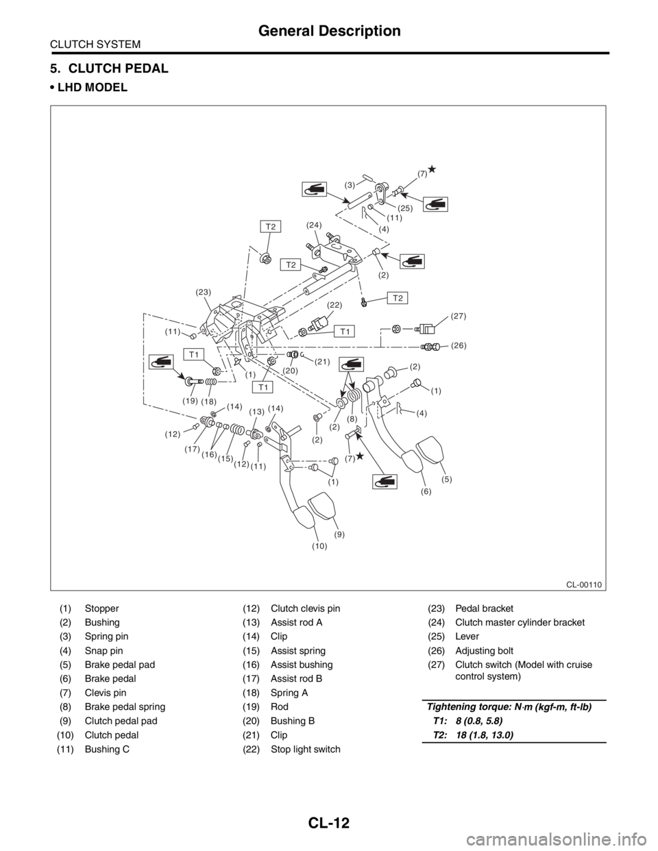
5. CLUTCH PEDAL
LHD MODEL
(1) Stopper (12) Clutch clevis pin (23) Pedal bracket
(2) Bushing (13) Assist rod A (24) Clutch master cylinder bracket
(3) Spring pin (14) Clip (25) Lever
(4) Snap pin (15) Assist spring (26) Adjusting bolt
(5) Brake pedal pad (16) Assist bushing (27) Clutch switch (Model with cruise
control system)
(6) Brake pedal (17) Assist rod B
(7) Clevis pin (18) Spring A
(8) Brake pedal spring (19) RodTightening torque: N
⋅m (kgf-m, ft-lb)
(9) Clutch pedal pad (20) Bushing BT1: 8 (0.8, 5.8)
(10) Clutch pedal (21) ClipT2: 18 (1.8, 13.0)
(11) Bushing C (22) Stop light switch
CL-00110
(7)
(7) (12)
T1
T1
T1
T2
T2
T2(25)
(11)
(11)(4)
(2) (3)
(24)
(22)
(26)
(21)
(20)
(1)
(1)(1) (2)
(2)
(6)
(9)
(10) (11) (12) (15) (16) (17) (19)
(18)
(14)
(13)(14)
(5) (2)(8)(4) (23)
(27)
Page 2839 of 2870

CLUTCH SYSTEM
General Description
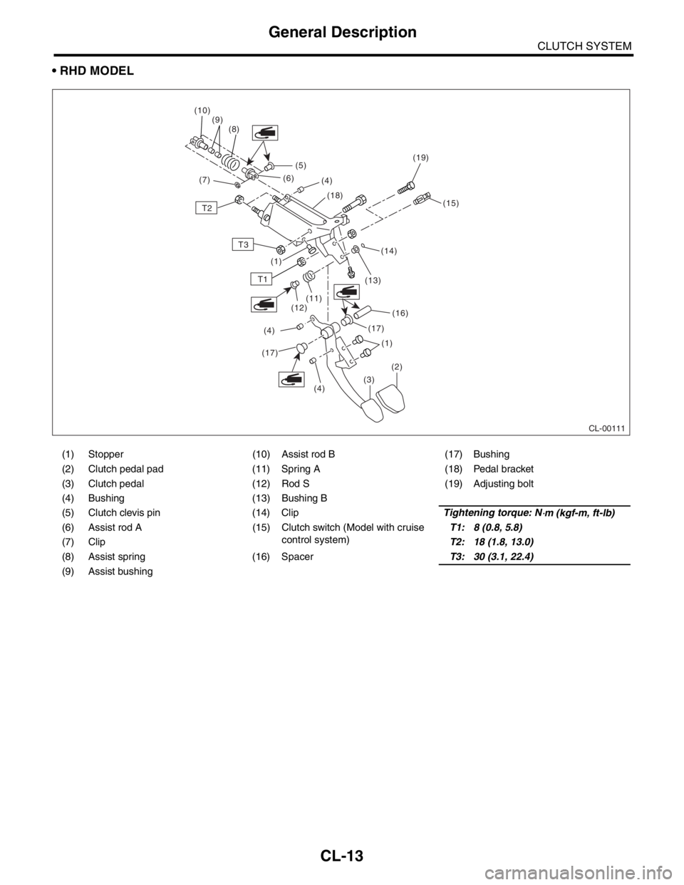
RHD MODEL
(1) Stopper (10) Assist rod B (17) Bushing
(2) Clutch pedal pad (11) Spring A (18) Pedal bracket
(3) Clutch pedal (12) Rod S (19) Adjusting bolt
(4) Bushing (13) Bushing B
(5) Clutch clevis pin (14) ClipTightening torque: N
⋅m (kgf-m, ft-lb)
(6) Assist rod A (15) Clutch switch (Model with cruise control system)T1: 8 (0.8, 5.8)
(7) Clip T2: 18 (1.8, 13.0)
(8) Assist spring (16) Spacer T3: 30 (3.1, 22.4)
(9) Assist bushing
CL-00111
(5)
T2
T3
T1
(16)
(13)
(14) (15)
(18)
(4)
(6)
(8)
(9)
(10)
(7)
(17)(1)
(1)
(2)
(3)
(4)
(17)
(4) (12)
(11)
(19)
CL-13
Page 2861 of 2870

CL-35
CLUTCH SYSTEM
Clutch Pedal
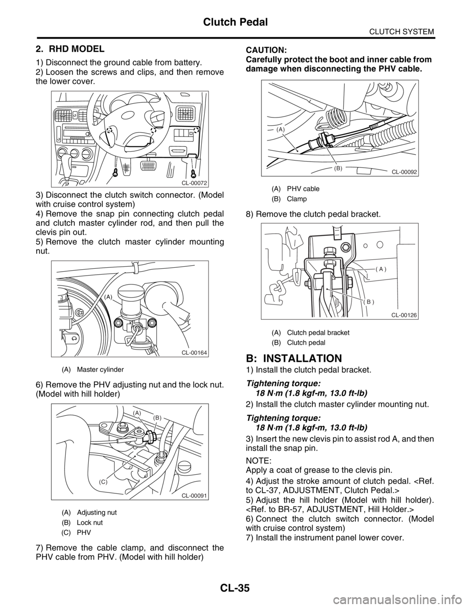
2. RHD MODEL
1) Disconnect the ground cable from battery.
2) Loosen the screws and clips, and then remove
the lower cover.
3) Disconnect the clutch switch connector. (Model
with cruise control system)
4) Remove the snap pin connecting clutch pedal
and clutch master cylinder rod, and then pull the
clevis pin out.
5) Remove the clutch master cylinder mounting
nut.
6) Remove the PHV adjusting nut and the lock nut.
(Model with hill holder)
7) Remove the cable clamp, and disconnect the
PHV cable from PHV. (Model with hill holder)CAUTION:
Carefully protect the boot and inner cable from
damage when disconnecting the PHV cable.
8) Remove the clutch pedal bracket.
B: INSTALLATION
1) Install the clutch pedal bracket.
Tightening torque:
18 N
⋅m (1.8 kgf-m, 13.0 ft-lb)
2) Install the clutch master cylinder mounting nut.
Tightening torque:
18 N
⋅m (1.8 kgf-m, 13.0 ft-lb)
3) Insert the new clevis pin to assist rod A, and then
install the snap pin.
NOTE:
Apply a coat of grease to the clevis pin.
4) Adjust the stroke amount of clutch pedal.
5) Adjust the hill holder (Model with hill holder).
6) Connect the clutch switch connector. (Model
with cruise control system)
7) Install the instrument panel lower cover.
(A) Master cylinder
(A) Adjusting nut
(B) Lock nut
(C) PHV
CL-00072
CL-00164
(A)
CL-00091
(C)(B) (A)
(A) PHV cable
(B) Clamp
(A) Clutch pedal bracket
(B) Clutch pedal
(B) (A)
CL-00092
( A )
( B )
CL-00126
Page 2862 of 2870

CL-36
CLUTCH SYSTEM
Clutch Pedal
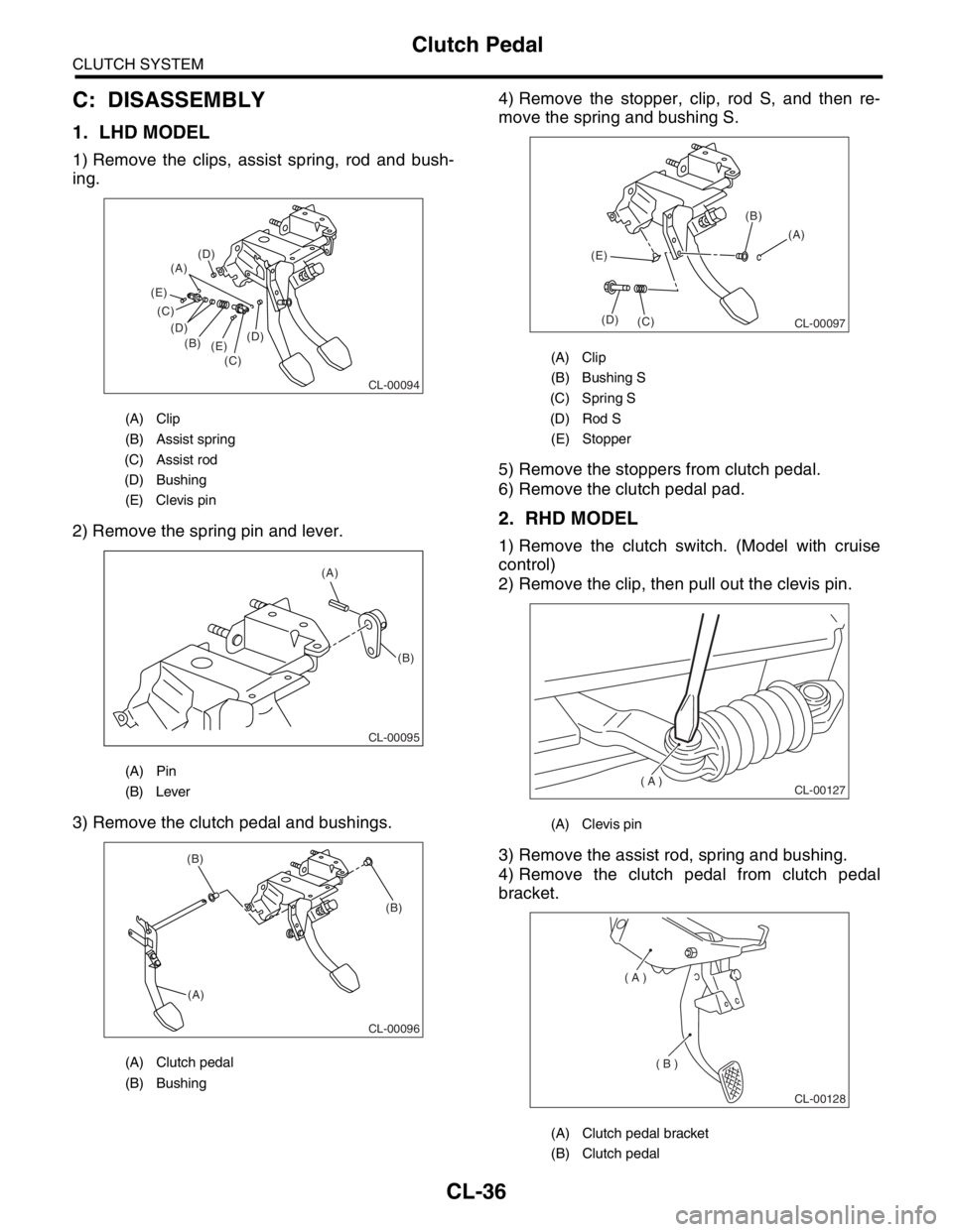
C: DISASSEMBLY
1. LHD MODEL
1) Remove the clips, assist spring, rod and bush-
ing.
2) Remove the spring pin and lever.
3) Remove the clutch pedal and bushings.4) Remove the stopper, clip, rod S, and then re-
move the spring and bushing S.
5) Remove the stoppers from clutch pedal.
6) Remove the clutch pedal pad.
2. RHD MODEL
1) Remove the clutch switch. (Model with cruise
control)
2) Remove the clip, then pull out the clevis pin.
3) Remove the assist rod, spring and bushing.
4) Remove the clutch pedal from clutch pedal
bracket.
(A) Clip
(B) Assist spring
(C) Assist rod
(D) Bushing
(E) Clevis pin
(A) Pin
(B) Lever
(A) Clutch pedal
(B) Bushing
CL-00094
(A)
(B)
(C) (C)
(D) (D)
(D)
(E) (E)
(A)
(B)
CL-00095
CL-00096
(A)(B) (B)
(A) Clip
(B) Bushing S
(C) Spring S
(D) Rod S
(E) Stopper
(A) Clevis pin
(A) Clutch pedal bracket
(B) Clutch pedal
CL-00097
(A) (B)
(C) (D) (E)
( A )
CL-00127
( A )
( B )
CL-00128