2004 SUBARU FORESTER engine
[x] Cancel search: enginePage 2293 of 2870

CS-8
CONTROL SYSTEM
Select Lever
2. Select Lever
A: REMOVAL
1) Set the vehicle on a lift.
2) Disconnect the ground cable from battery.
3) Shift the select lever to “N” range.
4) Lift-up the vehicle.
5) Remove the rear exhaust pipe and muffler.
Non-turbo model
Turbo model
6) Remove the heat shield cover. (If equipped)
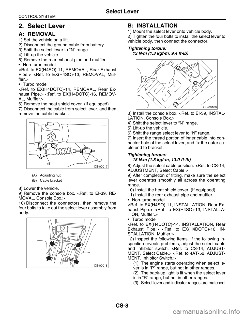
7) Disconnect the cable from select lever, and then
remove the cable bracket.
8) Lower the vehicle.
9) Remove the console box.
10) Disconnect the connectors, then remove the
four bolts to take out the select lever assembly from
body.
B: INSTALLATION
1) Mount the select lever onto vehicle body.
2) Tighten the four bolts to install the select lever to
vehicle body, then connect the connector.
Tightening torque:
13 N·m (1.3 kgf-m, 9.4 ft-lb)
3) Install the console box.
4) Shift the select lever to “N” range.
5) Lift-up the vehicle.
6) Shift the range select lever to “N” range.
7) Insert the thread portion of inner cable into con-
nector hole of the select lever, and fix the outer ca-
ble end to bracket.
Tightening torque:
18 N·m (1.8 kgf-m, 13.0 ft-lb)
8) Adjust the select cable position.
9) After completion of fitting, make sure the select
lever operates smoothly all across the operating
range.
10) Install the heat shield cover. (If equipped)
11) Install the rear exhaust pipe and muffler.
Non-turbo model
Turbo model
12) Inspect the following items. If the following in-
spection reveals problems, adjust the select cable
and inhibitor switch.
(1) The engine starts operating when select le-
ver is in “P” range, but not in other ranges.
(2) The back-up light is lit when the select lever
is in “R” range, but not in other ranges.
(3) Select lever and indicator ranges are matched.
(A) Adjusting nut
(B) Cable bracket
CS-00017(B)(A)
CS-00018
CS-00168
Page 2314 of 2870

4AT-2
AUTOMATIC TRANSMISSION
General Description
1. General Description
A: SPECIFICATION
1. TORQUE CONVERTER CLUTCH
2. OIL PUMP
3. TRANSMISSION CONTROL ELEMENT
4. TRANSMISSION GEAR RATIO5. PLANETARY GEAR AND PLATE
Model2.0 L
Non-
turbo2.5 L
Non-
turbo2.0 L
Tu r b o2.5 L
Tu r b o
Ty p eSymmetric, 3 element, single stage, 2 phase
torque converter
Stall torque
ratio2.0 —
2.21.9 —
2.11.85 —
2.152.05 —
2.35
Nominal
diameter246 mm (9.69 in)
Stall speed
(at sea level)2,000 —
2,500
rpm2,100 —
2,600
rpm2,600 —
3,300
rpm2,700 —
3,200
rpm
One-way
clutchSprague type one-way clutch
Type Pracoid constant-displacement pump
Driving method Driven by engine
Number of teethInner rotor 9
Outer rotor 10
Ty p e4-forward, 1-reverse, double-row plan-
etary gears
Multi-plate clutch 3 sets
Multi-plate brake 2 sets
One-way clutch
(sprague type)1 sets
Gear ratio
1st 2.785
2nd 1.545
3rd 1.000
4th 0.694
Rev 2.272
Model2.0 L Non-
turbo2.5 L Non-
turboTu r b o
Tooth num-
ber of front
sun gear33
Front pinion
number of
teeth21
Front inter-
nal gear
number of
teeth75
Tooth num-
ber of rear
sun gear42
Rear pinion
number of
teeth17
Tooth num-
ber of rear
internal gear75
Drive &
driven plate
number of
high clutch45
Drive &
driven plate
number of
low clutch467
Drive &
driven plate
number of
reverse
clutch2
Drive &
driven plate
number of 2-
4 brake34
Drive &
driven plate
number of
low &
reverse
brake467
Page 2315 of 2870

4AT-3
AUTOMATIC TRANSMISSION
General Description
6. SELECTOR POSITION
7. HYDRAULIC CONTROL AND LUBRICA-
TION
8. COOLING AND HARNESS9. TRANSFER
P (Park)Transmission in neutral, output member immov-
able, and engine start possible
R
(Reverse)Transmission in reverse
N (Neu-
tral)Transmission in neutral and engine start possi-
ble
D (Drive)Automatic gear change 1st
←
→ 2nd ←
→ 3rd ←
→
4th
3 (3rd)Automatic gear change 1st
←
→ 2nd ←
→ 3rd ←
4th
2 (2nd)Automatic gear change 1st
←
→ 2nd ← 3rd ←
4th
1 (1st)1st gear locked (Deceleration possible 1st ←
2nd ← 3rd ← 4th)
Control
methodWire cable type
Ty p eElectronic/hydraulic control
[Four forward speed
changes by electrical signals
of vehicle speed and accel-
erator (throttle) opening]
FluidDEXRON III type automatic
transmission fluid
Fluid capac-
ity2.0 L Non-
turbo model8.4 — 8.72 (8.9 — 9.2 US
qt, 7.4 — 7.7 Imp qt)
Except for
2.0 L Non-
turbo model9.3 — 9.62 (9.8 — 10.1 US
qt, 8.2 — 8.4 Imp qt)
Lubrication systemForced feed lubrication with
oil pump
OilAutomatic transmission fluid
(above mentioned)
Cooling SystemLiquid-cooled cooler incorpo-
rated in radiator
Inhibitor switch 12 poles
Transmission harness 20 poles
Model2.0 L Non-
turbo2.5 L Non-
turboTu r b o
Transfer
typeMulti-plate transfer (MPT)
Drive &
driven plate
number of
transfer
clutch456
Control
methodElectronic, hydraulic type
LubricantThe same Automatic transmission fluid used
in automatic transmission
Reduction
gear ratio1.000 (53/53)
Page 2328 of 2870

4AT-16
AUTOMATIC TRANSMISSION
General Description
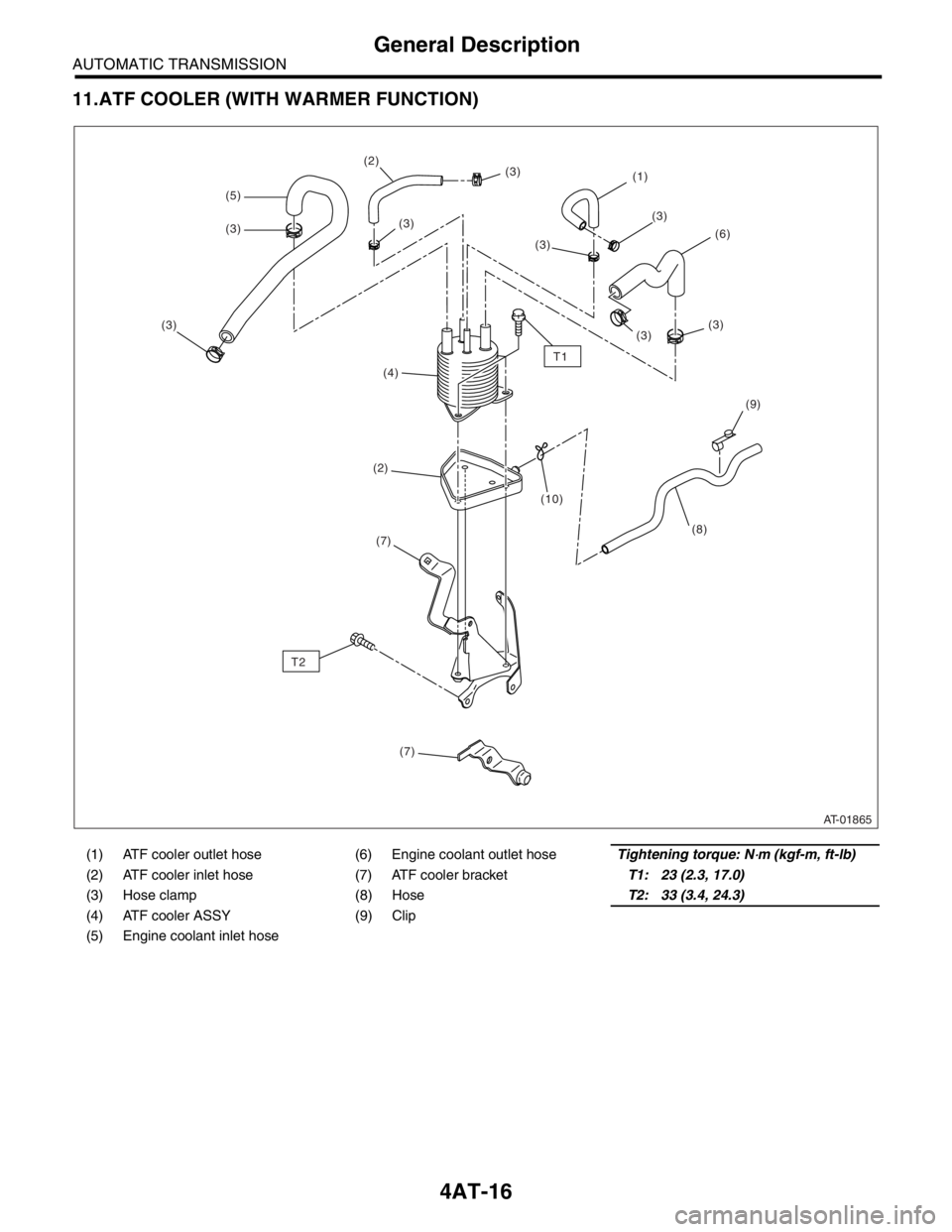
11.ATF COOLER (WITH WARMER FUNCTION)
(1) ATF cooler outlet hose (6) Engine coolant outlet hoseTightening torque: N⋅m (kgf-m, ft-lb)
(2) ATF cooler inlet hose (7) ATF cooler bracketT1: 23 (2.3, 17.0)
(3) Hose clamp (8) HoseT2: 33 (3.4, 24.3)
(4) ATF cooler ASSY (9) Clip
(5) Engine coolant inlet hose
AT-01865
T1
(1)
(6)
(4)
(2)
(3)
(5)
(3)(3)
(3)
(3)
(3)
(2)
(3)
(3)
(7) T2
(7)(8)
(10)
(9)
Page 2332 of 2870

4AT-20
AUTOMATIC TRANSMISSION
General Description
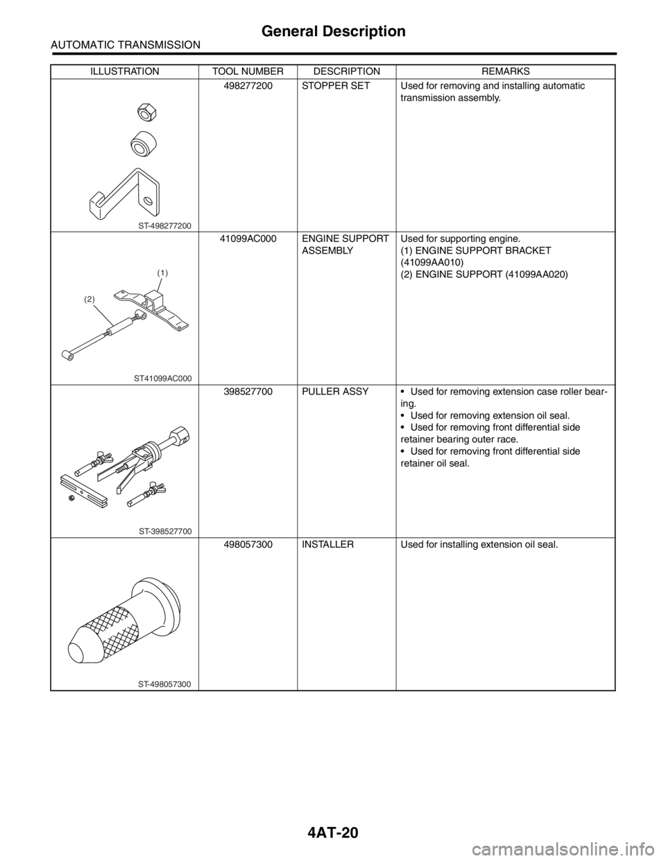
498277200 STOPPER SET Used for removing and installing automatic
transmission assembly.
41099AC000 ENGINE SUPPORT
ASSEMBLYUsed for supporting engine.
(1) ENGINE SUPPORT BRACKET
(41099AA010)
(2) ENGINE SUPPORT (41099AA020)
398527700 PULLER ASSY Used for removing extension case roller bear-
ing.
Used for removing extension oil seal.
Used for removing front differential side
retainer bearing outer race.
Used for removing front differential side
retainer oil seal.
498057300 INSTALLER Used for installing extension oil seal. ILLUSTRATION TOOL NUMBER DESCRIPTION REMARKS
ST-498277200
(2)(1)
ST41099AC000
ST-398527700
ST-498057300
Page 2342 of 2870

4AT-30
AUTOMATIC TRANSMISSION
Automatic Transmission Fluid
2. Automatic Transmission Flu-
id
A: INSPECTION
NOTE:
The level of ATF varies with fluid temperature. Pay
attention to the ATF temperature when checking
ATF level.
1) Raise the ATF temperature by driving a distance
of 5 to 10 km (3 to 6 miles). Otherwise, idle the en-
gine to raise ATF temperature to 70 — 80°C (158
— 176°F) on Subaru Select Monitor.
TION, Subaru Select Monitor.>
2) Make sure the vehicle is level.
3) After selecting all positions (P, R, N, D, 3, 2, 1),
set the select lever in “P” range. Measure the ATF
level with engine idling for one or two minutes.
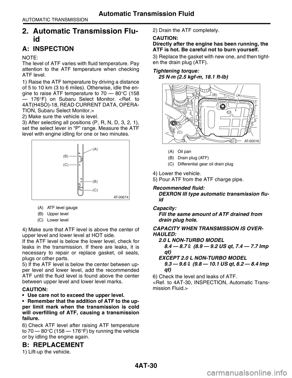
4) Make sure that ATF level is above the center of
upper level and lower level at HOT side.
If the ATF level is below the lower level, check for
leaks in the transmission. If there are leaks, it is
necessary to repair or replace gasket, oil seals,
plugs or other parts.
5) If the ATF level is below the center between up-
per level and lower level, add the recommended
ATF until the fluid level is found above the center
between upper level and lower level marks.
CAUTION:
Use care not to exceed the upper level.
Remember that the addition of ATF to the up-
per limit mark when the transmission is cold
will overfilling of ATF, causing a transmission
failure.
6) Check ATF level after raising ATF temperature
to 70 — 80°C (158 — 176°F) by running the vehicle
or by idling the engine again.
B: REPLACEMENT
1) Lift-up the vehicle.2) Drain the ATF completely.
CAUTION:
Directly after the engine has been running, the
ATF is hot. Be careful not to burn yourself.
3) Replace the gasket with new one, and then tight-
en the drain plug (ATF).
Tightening torque:
25 N
⋅m (2.5 kgf-m, 18.1 ft-lb)
4) Lower the vehicle.
5) Pour ATF from the ATF charge pipe.
Recommended fluid:
DEXRON III type automatic transmission flu-
id
Capacity:
Fill the same amount of ATF drained from
drain plug hole.
CAPACITY WHEN TRANSMISSION IS OVER-
HAULED:
2.0 L NON-TURBO MODEL
8.4 — 8.72 (8.9 — 9.2 US qt, 7.4 — 7.7 Imp
qt)
EXCEPT 2.0 L NON-TURBO MODEL
9.3 — 9.62 (9.8 — 10.1 US qt, 8.2 — 8.4 Imp
qt)
6) Check the level and leaks of ATF.
(A) ATF level gauge
(B) Upper level
(C) Lower level
AT-00674
COLD
LFHOT LF
(C)
(C)
(B)
(B)
(A)(A) Oil pan
(B) Drain plug (ATF)
(C) Differential gear oil drain plug
AT-00016
(A) (B)
(C)
Page 2344 of 2870

4AT-32
AUTOMATIC TRANSMISSION
Road Test
4. Road Test
A: INSPECTION
1. GENERAL PRECAUTION
Road tests should be conducted to properly diag-
nose the condition of the automatic transmission.
NOTE:
When performing the test, do not exceed posted
speed limit.
2. D RANGE SHIFT FUNCTION
Check shifting between 1st ←→ 2nd ←→ 3rd ←→
4th while driving on normal city streets.
3. D RANGE SHIFT SHOCK
Check the shock level when shifting up during nor-
mal driving.
4. KICK-DOWN FUNCTION
Check kick-down for each gear. Also check the
kick-down shock level.
5. ENGINE BRAKE OPERATION
Check the 3rd gear engine brake when shifting
down from D ←→ 3rd range while driving in 4th
gear of D range [50 — 60 km/h (31 — 37 MPH)].
Check the 2nd gear engine brake when shifting
between 3rd ←→ 2nd range while driving in the 3rd
range of 3rd gear [40 — 50 km/h (25 — 31 MPH)].
Check the 1st gear engine brake when shifting
between 2nd ←→ 1st range while driving in the 2nd
range of 2nd gear [20 — 30 km/h (12 — 19 MPH)].
6. LOCK-UP FUNCTION
Check that rpm does not change sharply when
the axle pedal is lightly depressed when driving on
flat roads at 60 km/h (37 MPH).
Check slip lock-up with following procedure.
Subaru Select Monitor is needed for checking (EC,
EK model).
Before start checking, check that the DTC is not ex-
isted using Subaru Select Monitor. When the DTC
is existed, perform the collective action with DTC
and check that the DTC is not existed again, and
then start the checking.
1) The check performed on flat and straight road or
free roller.
NOTE:
Slip lock-up does not operate when the vehicle is
lifted up, because of not occurring surface resis-
tance.
Also checking on the free roller, check with de-
pressing foot brake lightly to make the checking
easier, because the surface resistance will be defi-
cient2) Connect the Subaru Select Monitor.
3) Check ATF temperature using Subaru Select
Monitor.
NOTE:
ATF temperature is between 50 — 100°C (122
— 212°F).
When the temperature is low, warm-up the ATF
by running the vehicle or etc.
4) Start the engine, and make the lock-up duty be
able to read on data display of Subaru Select Mon-
itor.
5) 35 — 40 Drive the vehicle at a constant speed of
35 — 40 km/h (22 — 25 MPH).
6) Read the lock-up duty while vehicle is running.
Standard value:
25 — 45%
NOTE:
On the free roller, the value sometimes lowers.
Slip lock-up control is not operating when the
lock-up duty is less than 5%, or when the lock-up
duty goes down immediately after starts rise. On
these cases, improper ATF or deterioration of ATF
may be the cause. Check the amount of ATF or re-
place them, and then recheck it.
7. P RANGE OPERATION
Stop the vehicle on an uphill grade of 5% or more
and shift to “P” range. Check that the vehicle does
not move when the parking brake is released.
8. NOISE AND VIBRATION
Check for unusual sounds and vibration while driv-
ing and during shifting.
9. CLIMBING CONTROL FUNCTION
Check that the gear remains in 3rd when going
up a grade.
Check that the gear remains in 3rd when apply-
ing the brakes while going down a grade.
10.TRANSFER CLUTCH
Check tight corner braking when the vehicle started
with steering fully turned.
11.OIL LEAKS
After the driving test, inspect for oil leaks.
Page 2345 of 2870

4AT-33
AUTOMATIC TRANSMISSION
Stall Test
5. Stall Test
A: INSPECTION
NOTE:
The stall test is of extreme importance in diagnos-
ing the condition of the automatic transmission and
the engine. It should be conducted to measure the
engine stall speeds in “R” and “2” ranges (when
HOLD switch is ON).
Purposes of the stall test:
To check the operation of the automatic trans-
mission clutch.
To check the operation of the torque converter
clutch.
To check engine performance.
1) Check that the throttle valve opens fully.
2) Check that the engine oil level is correct.
3) Check that the coolant level is correct.
4) Check that the ATF level is correct.
5) Check that the differential gear oil level is cor-
rect.
6) Increase ATF temperature to 70 — 80°C (158 —
176°F) by idling the engine for approximately 30
minutes (with select lever set to “N” or “P”).
7) Place the wheel chocks at the front and rear of
all wheels and engage the parking brake.
8) Shift the manual linkage to ensure it operates
properly, then shift the select lever to the “2” range
and turn the HOLD switch to ON.
9) While forcibly depressing the foot brake pedal,
gradually depress the accelerator pedal until the
engine operates at full throttle.
10) When the engine speed is stabilized, record
that speed quickly and release the accelerator ped-
al.
11) Shift the select lever to “N” range, and cool
down the engine by idling it for more than one
minute.12) If the stall speed in “2” range (with HOLD switch
ON) is higher than specifications, low clutch slip-
ping and “2-4 brake slipping” may occur. To identify
it, conduct the same test as above in “R” range.
13) Perform the stall tests with the select lever in
the “D” range.
NOTE:
Do not continue the stall test for more than five
seconds at a time (from closed throttle, fully open
throttle to stall speed reading). Failure to follow this
instruction causes the engine oil and ATF to deteri-
orate and the clutch and brake to be adversely af-
fected.
Be sure to cool down the engine for at least one
minute after each stall test with the select lever set
in the “P” or “N” range and with the idle speed lower
than 1,200 rpm.
If the stall speed is higher than the specified
range, attempt to finish the stall test in as short a
time as possible, in order to prevent the automatic
transmission from sustaining damage.
Stall speed (at sea level):
2.0 L NON-TURBO MODEL
2,000 — 2,500 rpm
2.0 L TURBO MODEL
2,600 — 3,300 rpm
2.5 L NON-TURBO MODEL
2,100 — 2,600 rpm
2.5 L TURBO MODEL
2,700 — 3,200 rpm
(A) Brake pedal
(B) Accelerator pedal
(A) (B)
P
R
N
D
3
2
1
AT-00449