Page 2346 of 2870
4AT-34
AUTOMATIC TRANSMISSION
Stall Test
Stall speed (at sea level) Range Cause
Less than standard2 (Hold switch ON),
R Throttle valve not fully open
Erroneous engine operation
Torque converter clutch’s one-way clutch slipping
More than standardD Line pressure is too low
Low clutch slipping
One-way clutch malfunctioning
R Line pressure is too low
Reverse clutch slipping
Low & reverse brake slipping
2 (HOLD switch
ON) Line pressure is too low
Low clutch slipping
2-4 brake slipping
Page 2347 of 2870

4AT-35
AUTOMATIC TRANSMISSION
Time Lag Test
6. Time Lag Test
A: INSPECTION
NOTE:
If the select lever is shifted while the engine is
idling, there will be a certain time elapse or lag be-
fore the shock can be felt. This is used for checking
the condition of the low clutch, reverse clutch, low &
reverse brake and one-way clutch.
Perform the test at normal operation fluid tem-
perature 70 — 80°C (158 — 176°F).
Be sure to allow a one minute interval between
tests.
Perform measurement for three times and take
the average value.
1) Fully apply the parking brake.
2) Start the engine.
Check the idling speed (A/C OFF).
3) Shift the select lever from “N” to “D” range.
Using a stop watch, measure the time it takes from
shifting the lever until the shock is felt.
Time lag: Less than 1.2 seconds
If “N” → “D” time lag is longer than specified:
Line pressure too low
Low clutch worn
One-way clutch not operating properly
D-ring worn
4) In the same manner, measure the time lag for
“N” → “R”.
Time lag: Less than 1.5 seconds
If “N” → “R” time lag is longer than specified:
Line pressure too low
Reverse clutch worn
Low & reverse brake worn
D-ring worn
Page 2348 of 2870

4AT-36
AUTOMATIC TRANSMISSION
Line Pressure Test
7. Line Pressure Test
A: MEASUREMENT
NOTE:
If the clutch or the brake shows a sign of slippage or
shifting sensation is not correct, the line pressure
should be checked.
Excessive shocks during upshifting or shifting
takes place at a higher point than under normal cir-
cumstances, may be due to the line pressure being
too high.
Slippage or inability to operate the vehicle may,
in most cases, be due to insufficient oil pressure for
the operation of the clutch, brake or control valve.
1) Line pressure measurement (under no load):
(1) Before measuring line pressure, jack-up all
wheels.
(2) Maintain the temperature of ATF at approx.
70 — 80°C (158 — 176°F) during measurement.
(ATF will reach the above temperature after
idling the engine for approx. 30 minutes with the
select lever in “N” or “P”.)
2) Line pressure measurement (under heavy load):
(1) Before measuring line pressure, apply both
foot and parking brakes with all wheels chocked
(Same as for “stall” test conditions).
(2) Measure the line pressure when the select
lever is in “D”, “2” (HOLD switch ON) with engine
under stall conditions.
(3) Measure the line pressure within 5 seconds
after shifting the select lever to each position. (If
the line pressure needs to be measured again,
allow the engine to idle and cool it down more
than 1 minute.)
(4) Maintain the ATF temperature at approx. 70
— 80°C (158 — 176°F) during measurement.
(ATF will reach the above temperature after
idling the engine for approx. 30 minutes with the
select lever in “N” or “P”.)3) Temporarily attach the ST to a suitable place in
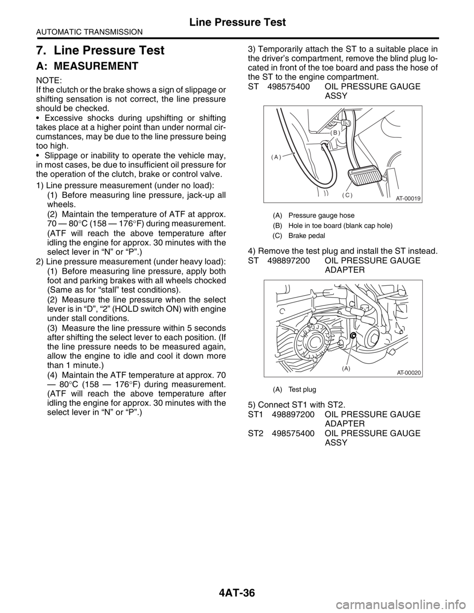
the driver’s compartment, remove the blind plug lo-
cated in front of the toe board and pass the hose of
the ST to the engine compartment.
ST 498575400 OIL PRESSURE GAUGE
ASSY
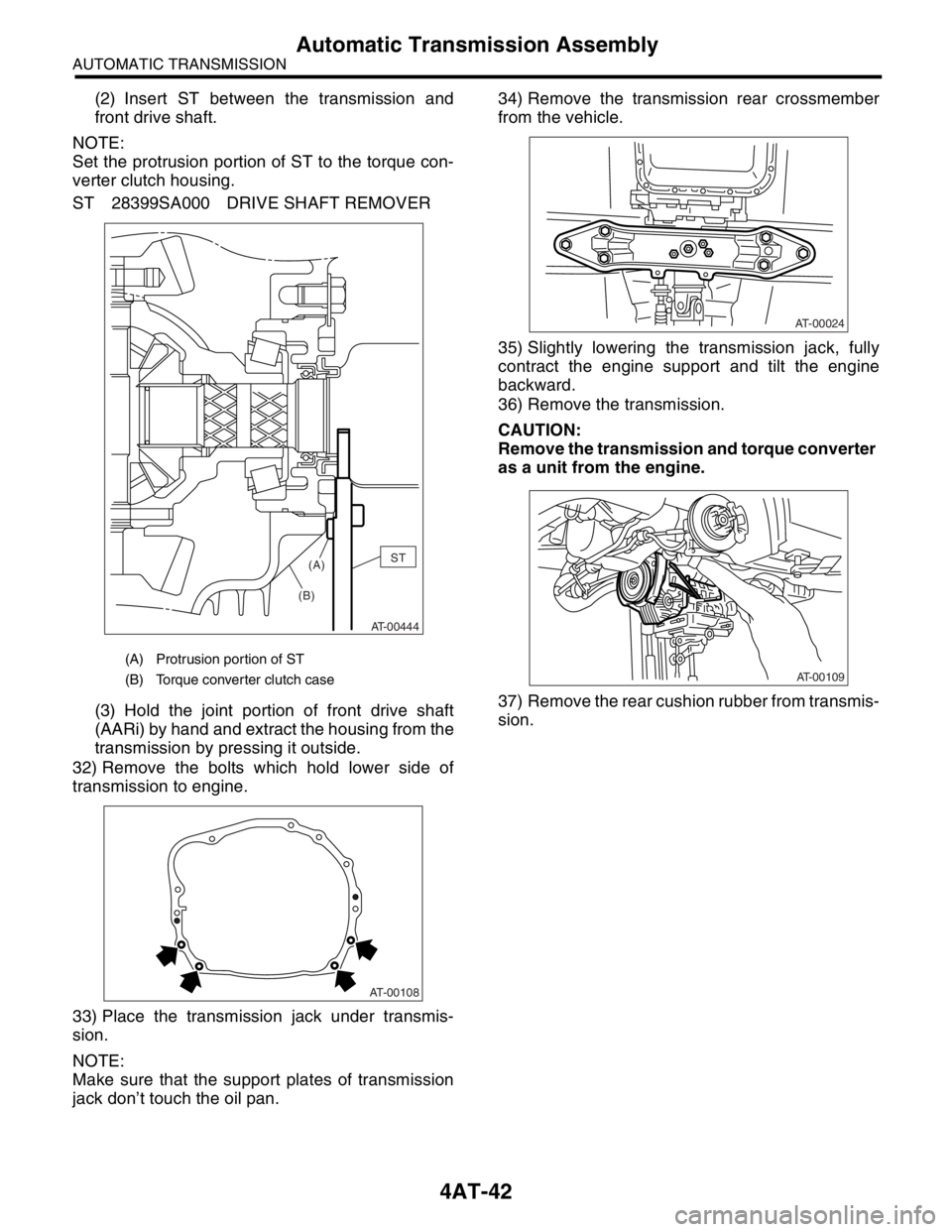
4) Remove the test plug and install the ST instead.
ST 498897200 OIL PRESSURE GAUGE
ADAPTER
5) Connect ST1 with ST2.
ST1 498897200 OIL PRESSURE GAUGE
ADAPTER
ST2 498575400 OIL PRESSURE GAUGE
ASSY
(A) Pressure gauge hose
(B) Hole in toe board (blank cap hole)
(C) Brake pedal
(A) Test plug
AT-00019
(A)(B)
(C)
AT-00020(A)
Page 2352 of 2870
4AT-40
AUTOMATIC TRANSMISSION
Automatic Transmission Assembly
13) Disconnect the hose from lower portion of ATF
cooler (with warmer function), and then secure the
ATF cooler to vehicle using string, etc.
14) Remove the pitching stopper.
15) Separate the torque converter clutch assembly
from drive plate.
(1) Remove the service hole plug.
(2) Remove the bolts which hold torque con-
verter clutch assembly to drive plate.
(3) Using ST, remove all bolts with slightly rotat-
ing crank sprocket.
CAUTION:
Be careful not to drop bolts into torque convert-
er clutch housing.16) Install the ST to torque converter clutch case.
ST 498277200 STOPPER SET
17) Remove the ATF level gauge.
CAUTION:
Plug the opening to prevent entering foreign
particles into transmission fluid.
18) Set ST.
ST 41099AC000 ENGINE SUPPORT ASSEM-
BLY
19) Remove the bolts which hold right upper side of
transmission to engine.
AT-02118
AT-00023
AT-00102
AT-00804
ST
AT-00680
AT-00105
ST
AT-00106
Page 2354 of 2870

4AT-42
AUTOMATIC TRANSMISSION
Automatic Transmission Assembly
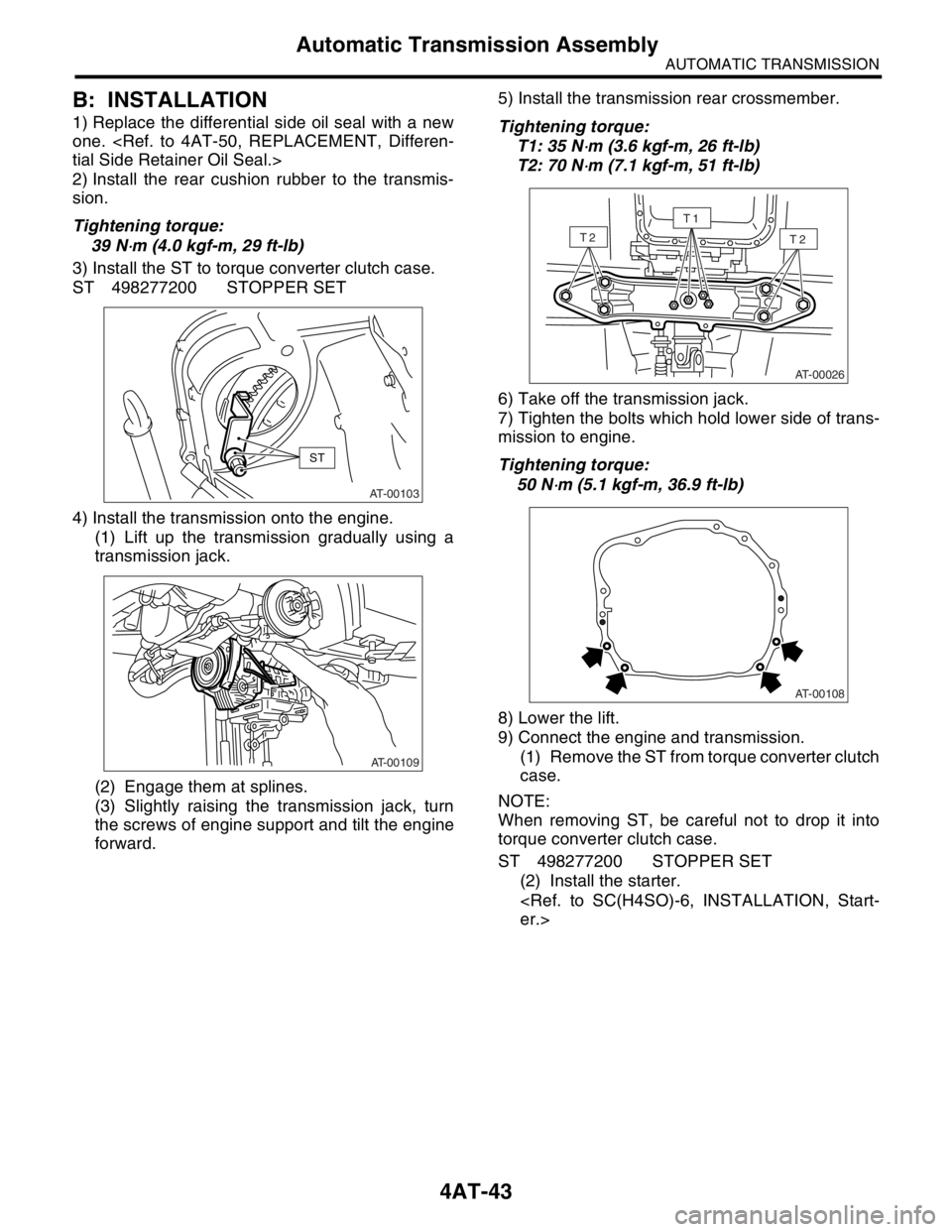
(2) Insert ST between the transmission and
front drive shaft.
NOTE:
Set the protrusion portion of ST to the torque con-
verter clutch housing.
ST 28399SA000 DRIVE SHAFT REMOVER
(3) Hold the joint portion of front drive shaft
(AARi) by hand and extract the housing from the
transmission by pressing it outside.
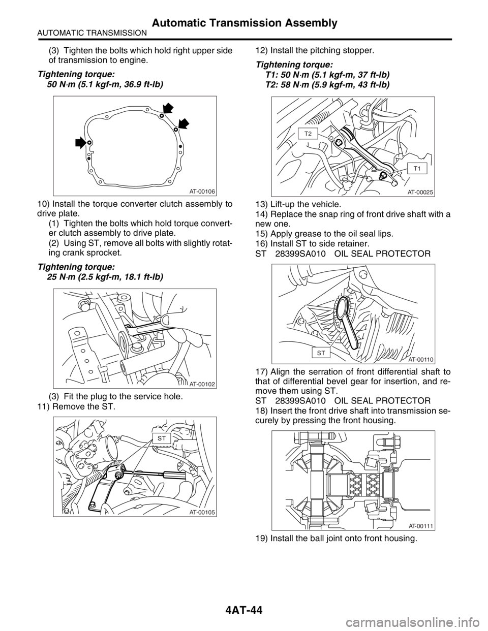
32) Remove the bolts which hold lower side of
transmission to engine.
33) Place the transmission jack under transmis-
sion.
NOTE:
Make sure that the support plates of transmission
jack don’t touch the oil pan.34) Remove the transmission rear crossmember
from the vehicle.
35) Slightly lowering the transmission jack, fully
contract the engine support and tilt the engine
backward.
36) Remove the transmission.
CAUTION:
Remove the transmission and torque converter
as a unit from the engine.
37) Remove the rear cushion rubber from transmis-
sion.
(A) Protrusion portion of ST
(B) Torque converter clutch case
AT-00444
ST
(A)
(B)
AT-00108
AT-00024
AT-00109
Page 2355 of 2870

4AT-43
AUTOMATIC TRANSMISSION
Automatic Transmission Assembly
B: INSTALLATION
1) Replace the differential side oil seal with a new
one.
tial Side Retainer Oil Seal.>
2) Install the rear cushion rubber to the transmis-
sion.
Tightening torque:
39 N
⋅m (4.0 kgf-m, 29 ft-lb)
3) Install the ST to torque converter clutch case.
ST 498277200 STOPPER SET
4) Install the transmission onto the engine.
(1) Lift up the transmission gradually using a
transmission jack.
(2) Engage them at splines.
(3) Slightly raising the transmission jack, turn
the screws of engine support and tilt the engine
forward.5) Install the transmission rear crossmember.
Tightening torque:
T1: 35 N
⋅m (3.6 kgf-m, 26 ft-lb)
T2: 70 N
⋅m (7.1 kgf-m, 51 ft-lb)
6) Take off the transmission jack.
7) Tighten the bolts which hold lower side of trans-
mission to engine.
Tightening torque:
50 N
⋅m (5.1 kgf-m, 36.9 ft-lb)
8) Lower the lift.
9) Connect the engine and transmission.
(1) Remove the ST from torque converter clutch
case.
NOTE:
When removing ST, be careful not to drop it into
torque converter clutch case.
ST 498277200 STOPPER SET
(2) Install the starter.
er.>AT-00103
ST
AT-00109
AT-00026
T2T2
T1
AT-00108
Page 2356 of 2870

4AT-44
AUTOMATIC TRANSMISSION
Automatic Transmission Assembly
(3) Tighten the bolts which hold right upper side
of transmission to engine.
Tightening torque:
50 N
⋅m (5.1 kgf-m, 36.9 ft-lb)
10) Install the torque converter clutch assembly to
drive plate.
(1) Tighten the bolts which hold torque convert-
er clutch assembly to drive plate.
(2) Using ST, remove all bolts with slightly rotat-
ing crank sprocket.
Tightening torque:
25 N
⋅m (2.5 kgf-m, 18.1 ft-lb)
(3) Fit the plug to the service hole.
11) Remove the ST.12) Install the pitching stopper.
Tightening torque:
T1: 50 N
⋅m (5.1 kgf-m, 37 ft-lb)
T2: 58 N
⋅m (5.9 kgf-m, 43 ft-lb)
13) Lift-up the vehicle.
14) Replace the snap ring of front drive shaft with a
new one.
15) Apply grease to the oil seal lips.
16) Install ST to side retainer.
ST 28399SA010 OIL SEAL PROTECTOR
17) Align the serration of front differential shaft to
that of differential bevel gear for insertion, and re-
move them using ST.
ST 28399SA010 OIL SEAL PROTECTOR
18) Insert the front drive shaft into transmission se-
curely by pressing the front housing.
19) Install the ball joint onto front housing.
AT-00106
AT-00102
AT-00105
ST
AT-00025
T1
T2
AT-00110ST
AT-00111
Page 2383 of 2870

4AT-70
AUTOMATIC TRANSMISSION
Air Bleeding of Control Valve
18.Air Bleeding of Control Valve
A: PROCEDURE
1) Lift-up the vehicle with shifting the select lever to
“P” range and applying the parking brake.
2) Connect the Subaru Select Monitor to the vehi-
cle.
3) Make sure there is no trouble code using Subaru
Select Monitor.
4) Using Subaru Select Monitor, check that the
ATF temperature is in less than 60°C (140°F).
nostic Procedure.>
5) Power OFF the Subaru Select Monitor.
6) Turn the ignition switch to “OFF”.
7) Shift the select lever to “R” range.
8) Depress the brake pedal fully until the air bleed-
ing is completed.
9) Turn the ignition switch to ON.
10) Shift the select lever to “P” range, and then wait
for more than 3 seconds.
11) Shift the select lever to “R” range, and then wait
for more than 3 seconds.
12) Shift the select lever to “N” range, and then wait
for more than 3 seconds.
13) Shift the select lever to “D” range, and then wait
for more than 3 seconds.
14) Shift the select lever to “N” range, and then wait
for more than 3 seconds.
15) Slightly depress the accelerator pedal fully.
16) Slightly release the accelerator pedal fully.
17) Start the engine.
18) Shift the select lever to “D” range.
19) Turn the Subaru Select Monitor switch to ON.
20) Select {Each System Check} in «Main Menu»
of Subaru Select Monitor.
21) On the «System Selection Menu» display
screen, select the “Transmission”. Air bleeding of
control valve starts on transmission. At this time,
the POWER indicator light in combination meter
blinks at 2 Hz. When the POWER indicator light
does not blink, repeat the procedures from step 4).
22) Air bleeding of control valve is finished when
blinking of POWER indicator light in combination
meter changes from 2 Hz to 0.5 Hz.
NOTE:
When blinking of POWER indicator light changes
from 2 Hz to 4 Hz during air bleeding, repeat the
procedure from step 4).
23) Shift the select lever to “N” range, and then turn
the ignition switch to OFF.
24) Shift the select lever to the “P” range, and then
finish the air bleeding.