Page 810 of 2870
FU(H4SO)-28
FUEL INJECTION (FUEL SYSTEM)
Knock Sensor
7. Knock Sensor
A: REMOVAL
1) Disconnect the ground cable from battery.
2) Remove the air cleaner case.
IN(H4SO)-6, REMOVAL, Air Cleaner Case.>
3) Disconnect the knock sensor connector.
4) Remove the knock sensor from the cylinder
block.
B: INSTALLATION
1) Install the knock sensor to the cylinder block.
Tightening torque:
24 N
⋅m (2.4 kgf-m, 17.4 ft-lb)
NOTE:
The extraction area of the knock sensor cord must
be positioned at a 60° angle relative to the engine
rear.
2) Connect the knock sensor connector.
3) Install the air cleaner case.
Case.>
4) Connect the battery ground cable to battery.
FU-00009
FU-00062
FU-00519
(A) Front side
FU-00413
(A)
60
FU-00062
FU-00009
Page 812 of 2870

FU(H4SO)-30
FUEL INJECTION (FUEL SYSTEM)
Throttle Position Sensor
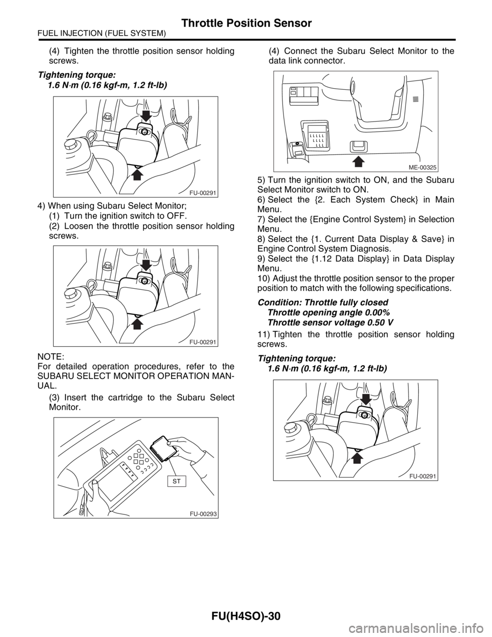
(4) Tighten the throttle position sensor holding
screws.
Tightening torque:
1.6 N
⋅m (0.16 kgf-m, 1.2 ft-lb)
4) When using Subaru Select Monitor;
(1) Turn the ignition switch to OFF.
(2) Loosen the throttle position sensor holding
screws.
NOTE:
For detailed operation procedures, refer to the
SUBARU SELECT MONITOR OPERATION MAN-
UAL.
(3) Insert the cartridge to the Subaru Select
Monitor.(4) Connect the Subaru Select Monitor to the
data link connector.
5) Turn the ignition switch to ON, and the Subaru
Select Monitor switch to ON.
6) Select the {2. Each System Check} in Main
Menu.
7) Select the {Engine Control System} in Selection
Menu.
8) Select the {1. Current Data Display & Save} in
Engine Control System Diagnosis.
9) Select the {1.12 Data Display} in Data Display
Menu.
10) Adjust the throttle position sensor to the proper
position to match with the following specifications.
Condition: Throttle fully closed
Throttle opening angle 0.00%
Throttle sensor voltage 0.50 V
11) Tighten the throttle position sensor holding
screws.
Tightening torque:
1.6 N
⋅m (0.16 kgf-m, 1.2 ft-lb)
FU-00291
FU-00291
FU-00293
ST
ME-00325
FU-00291
Page 822 of 2870

FU(H4SO)-40
FUEL INJECTION (FUEL SYSTEM)
Front Oxygen (A/F) Sensor
14.Front Oxygen (A/F) Sensor
A: REMOVAL
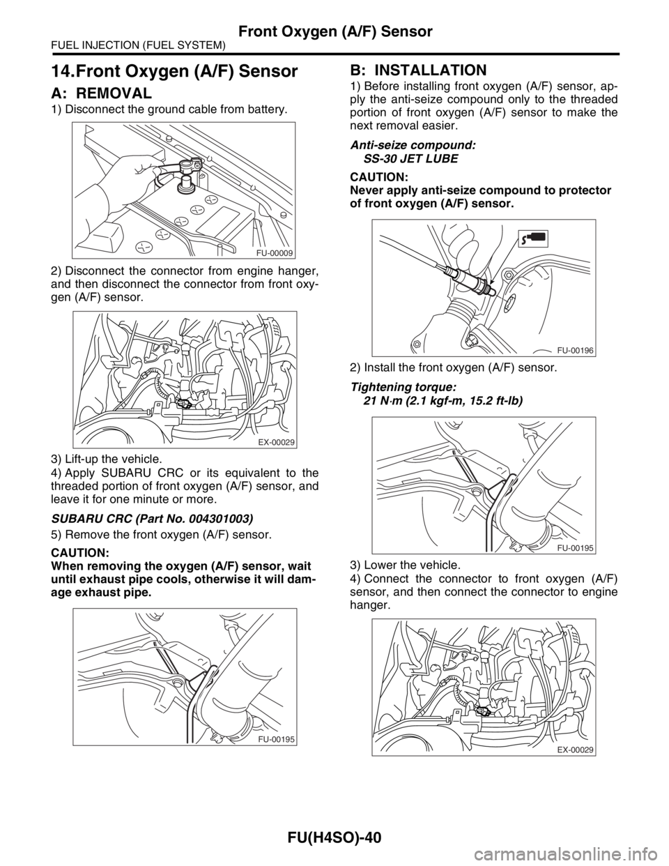
1) Disconnect the ground cable from battery.
2) Disconnect the connector from engine hanger,
and then disconnect the connector from front oxy-
gen (A/F) sensor.
3) Lift-up the vehicle.
4) Apply SUBARU CRC or its equivalent to the
threaded portion of front oxygen (A/F) sensor, and
leave it for one minute or more.
SUBARU CRC (Part No. 004301003)
5) Remove the front oxygen (A/F) sensor.
CAUTION:
When removing the oxygen (A/F) sensor, wait
until exhaust pipe cools, otherwise it will dam-
age exhaust pipe.
B: INSTALLATION
1) Before installing front oxygen (A/F) sensor, ap-
ply the anti-seize compound only to the threaded
portion of front oxygen (A/F) sensor to make the
next removal easier.
Anti-seize compound:
SS-30 JET LUBE
CAUTION:
Never apply anti-seize compound to protector
of front oxygen (A/F) sensor.
2) Install the front oxygen (A/F) sensor.
Tightening torque:
21 N
⋅m (2.1 kgf-m, 15.2 ft-lb)
3) Lower the vehicle.
4) Connect the connector to front oxygen (A/F)
sensor, and then connect the connector to engine
hanger.
FU-00009
EX-00029
FU-00195
FU-00196
FU-00195
EX-00029
Page 826 of 2870
FU(H4SO)-44
FUEL INJECTION (FUEL SYSTEM)
Engine Control Module (ECM)
16.Engine Control Module (ECM)
A: REMOVAL
1) Disconnect the ground cable from battery.
2) Remove the lower inner trim of passenger side.
3) Detach the floor mat of front passenger seat.
4) Remove the protect cover.
5) Remove the nuts (A) which hold ECM to the
bracket.
6) Remove the clip (B) from the bracket.
7) Disconnect the ECM connectors and take out
the ECM.
B: INSTALLATION
Install in the reverse order of removal.
CAUTION:
When replacing ECM, be careful not to use the
wrong spec. ECM to avoid any damage to the
fuel injection system.
Tightening torque:
5 N
⋅m (0.51 kgf-m, 3.7 ft-lb)
FU-00009
FU-00315
(A)
(A)
(B)
FU-00316
Page 829 of 2870
FU(H4SO)-47
FUEL INJECTION (FUEL SYSTEM)
Fuel
19.Fuel
A: OPERATION
1. RELEASING OF FUEL PRESSURE
WARNING:
Place “NO FIRE” signs near the working area.
Be careful not to spill fuel.
1) Disconnect the connector from fuel pump relay.
2) Start the engine and run it until it stalls.
3) After the engine stalls, crank it for 5 more sec-
onds.
4) Turn the ignition switch to OFF.
2. DRAINING FUEL
WARNING:
Place “NO FIRE” signs near the working area.
Be careful not to spill fuel.
1) Set the vehicle on a lift.
2) Disconnect the ground cable from battery.
3) Open the fuel filler flap lid and remove fuel filler
cap.
4) Lift-up the vehicle.5) Drain fuel from the fuel tank.
Set a container under the vehicle and remove the
drain plug from fuel tank.
6) Tighten the fuel drain plug.
Tightening torque:
26 N
⋅m (2.7 kgf-m, 19.2 ft-lb)
FU-00262
FU-00009
FU-00089
FU-00089
Page 845 of 2870
FU(H4SO)-63
FUEL INJECTION (FUEL SYSTEM)
Fuel Delivery, Return and Evaporation Lines
28.Fuel Delivery, Return and Evaporation Lines
A: REMOVAL
1) Set the vehicle on a lift.
2) Release the fuel pressure.
Fuel.>
3) Open the fuel filler flap lid and remove fuel filler cap.
4) Remove the floor mat.
5) Remove the fuel delivery pipes and hoses, fuel return pipes and hoses, evaporation pipes and hoses.
6) In the engine compartment, detach the fuel de-
livery hose (A), return hose (B) and evaporation
hose (C).
7) Lift-up the vehicle.8) Disconnect the two-way valve hose (A) from
two-way valve and disconnect the canister hose (B)
from canister.
FU-00122
(B) (A)
(C)
FU-00374
(A)(B)
FU-00091
Page 849 of 2870

FUJI HEAVY INDUSTRIES LTD. G8080GE2
2004 FORESTER SERVICE MANUAL QUICK REFERENCE INDEX
ENGINE SECTION 1
This service manual has been prepared
to provide SUBARU service personnel
with the necessary information and data
for the correct maintenance and repair
of SUBARU vehicles.
This manual includes the procedures
for maintenance, disassembling, reas-
sembling, inspection and adjustment of
components and diagnostics for guid-
ance of experienced mechanics.
Please peruse and utilize this manual
fully to ensure complete repair work for
satisfying our customers by keeping
their vehicle in optimum condition.
When replacement of parts during
repair work is needed, be sure to use
SUBARU genuine parts.
All information, illustration and specifi-
cations contained in this manual are
based on the latest product information
available at the time of publication
approval.FUEL INJECTION (FUEL SYSTEM) FU(H4SO)
EMISSION CONTROL
(AUX. EMISSION CONTROL DEVICE)EC(H4SO)
INTAKE (INDUCTION) IN(H4SO)
MECHANICAL ME(H4SO)
EXHAUST EX(H4SO)
COOLING CO(H4SO)
LUBRICATION LU(H4SO)
SPEED CONTROL SYSTEM SP(H4SO)
IGNITION IG(H4SO)
STARTING/CHARGING SYSTEM SC(H4SO)
ENGINE (DIAGNOSTIC) EN(H4SO)
Page 860 of 2870

FUJI HEAVY INDUSTRIES LTD. G8080GE2
2004 FORESTER SERVICE MANUAL QUICK REFERENCE INDEX
ENGINE SECTION 1
This service manual has been prepared
to provide SUBARU service personnel
with the necessary information and data
for the correct maintenance and repair
of SUBARU vehicles.
This manual includes the procedures
for maintenance, disassembling, reas-
sembling, inspection and adjustment of
components and diagnostics for guid-
ance of experienced mechanics.
Please peruse and utilize this manual
fully to ensure complete repair work for
satisfying our customers by keeping
their vehicle in optimum condition.
When replacement of parts during
repair work is needed, be sure to use
SUBARU genuine parts.
All information, illustration and specifi-
cations contained in this manual are
based on the latest product information
available at the time of publication
approval.FUEL INJECTION (FUEL SYSTEM) FU(H4SO)
EMISSION CONTROL
(AUX. EMISSION CONTROL DEVICE)EC(H4SO)
INTAKE (INDUCTION) IN(H4SO)
MECHANICAL ME(H4SO)
EXHAUST EX(H4SO)
COOLING CO(H4SO)
LUBRICATION LU(H4SO)
SPEED CONTROL SYSTEM SP(H4SO)
IGNITION IG(H4SO)
STARTING/CHARGING SYSTEM SC(H4SO)
ENGINE (DIAGNOSTIC) EN(H4SO)