Page 909 of 2870
ME(H4SO)-40
MECHANICAL
Engine Assembly
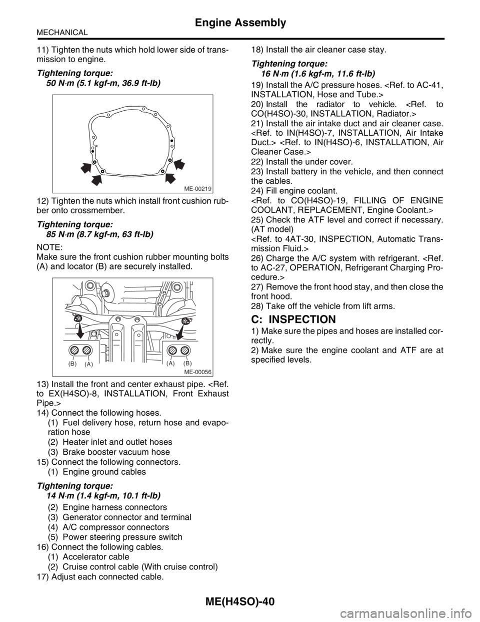
11) Tighten the nuts which hold lower side of trans-
mission to engine.
Tightening torque:
50 N
⋅m (5.1 kgf-m, 36.9 ft-lb)
12) Tighten the nuts which install front cushion rub-
ber onto crossmember.
Tightening torque:
85 N
⋅m (8.7 kgf-m, 63 ft-lb)
NOTE:
Make sure the front cushion rubber mounting bolts
(A) and locator (B) are securely installed.
13) Install the front and center exhaust pipe.
to EX(H4SO)-8, INSTALLATION, Front Exhaust
Pipe.>
14) Connect the following hoses.
(1) Fuel delivery hose, return hose and evapo-
ration hose
(2) Heater inlet and outlet hoses
(3) Brake booster vacuum hose
15) Connect the following connectors.
(1) Engine ground cables
Tightening torque:
14 N
⋅m (1.4 kgf-m, 10.1 ft-lb)
(2) Engine harness connectors
(3) Generator connector and terminal
(4) A/C compressor connectors
(5) Power steering pressure switch
16) Connect the following cables.
(1) Accelerator cable
(2) Cruise control cable (With cruise control)
17) Adjust each connected cable.18) Install the air cleaner case stay.
Tightening torque:
16 N
⋅m (1.6 kgf-m, 11.6 ft-lb)
19) Install the A/C pressure hoses.
INSTALLATION, Hose and Tube.>
20) Install the radiator to vehicle.
CO(H4SO)-30, INSTALLATION, Radiator.>
21) Install the air intake duct and air cleaner case.
Duct.>
Cleaner Case.>
22) Install the under cover.
23) Install battery in the vehicle, and then connect
the cables.
24) Fill engine coolant.
COOLANT, REPLACEMENT, Engine Coolant.>
25) Check the ATF level and correct if necessary.
(AT model)
mission Fluid.>
26) Charge the A/C system with refrigerant.
to AC-27, OPERATION, Refrigerant Charging Pro-
cedure.>
27) Remove the front hood stay, and then close the
front hood.
28) Take off the vehicle from lift arms.
C: INSPECTION
1) Make sure the pipes and hoses are installed cor-
rectly.
2) Make sure the engine coolant and ATF are at
specified levels.
ME-00219
ME-00056
(A)
(A)(B)
(B)
Page 910 of 2870
ME(H4SO)-41
MECHANICAL
Engine Mounting
10.Engine Mounting
A: REMOVAL
1) Remove the engine assembly.
ME(H4SO)-34, REMOVAL, Engine Assembly.>
2) Remove the engine mounting from engine as-
sembly.
B: INSTALLATION
Install in the reverse order of removal.
Tightening torque:
Engine mounting:
34 N
⋅m (3.5 kgf-m, 25.3 ft-lb)
C: INSPECTION
Make sure there are no cracks or other damage.
Page 911 of 2870
ME(H4SO)-42
MECHANICAL
Preparation for Overhaul
11.Preparation for Overhaul
A: PROCEDURE
1) After removing the engine from body, secure it in
the ST shown below.
ST1 498457000 ENGINE STAND ADAPTER
RH
ST2 498457100 ENGINE STAND ADAPTER
LH
ST3 499817100 ENGINE STAND
2) In this section the procedures described under
each index are all connected and stated in order. It
will be the complete procedure for overhauling of
the engine itself when you go through all steps in
the process.
Therefore, in this section, to conduct the particular
procedure within the flow of a section, you need to
go back and conduct the procedure described pre-
viously in order to do that particular procedure.
ME-00221ST2ST1ST3
Page 912 of 2870
ME(H4SO)-43
MECHANICAL
V-belt
12.V-belt
A: REMOVAL
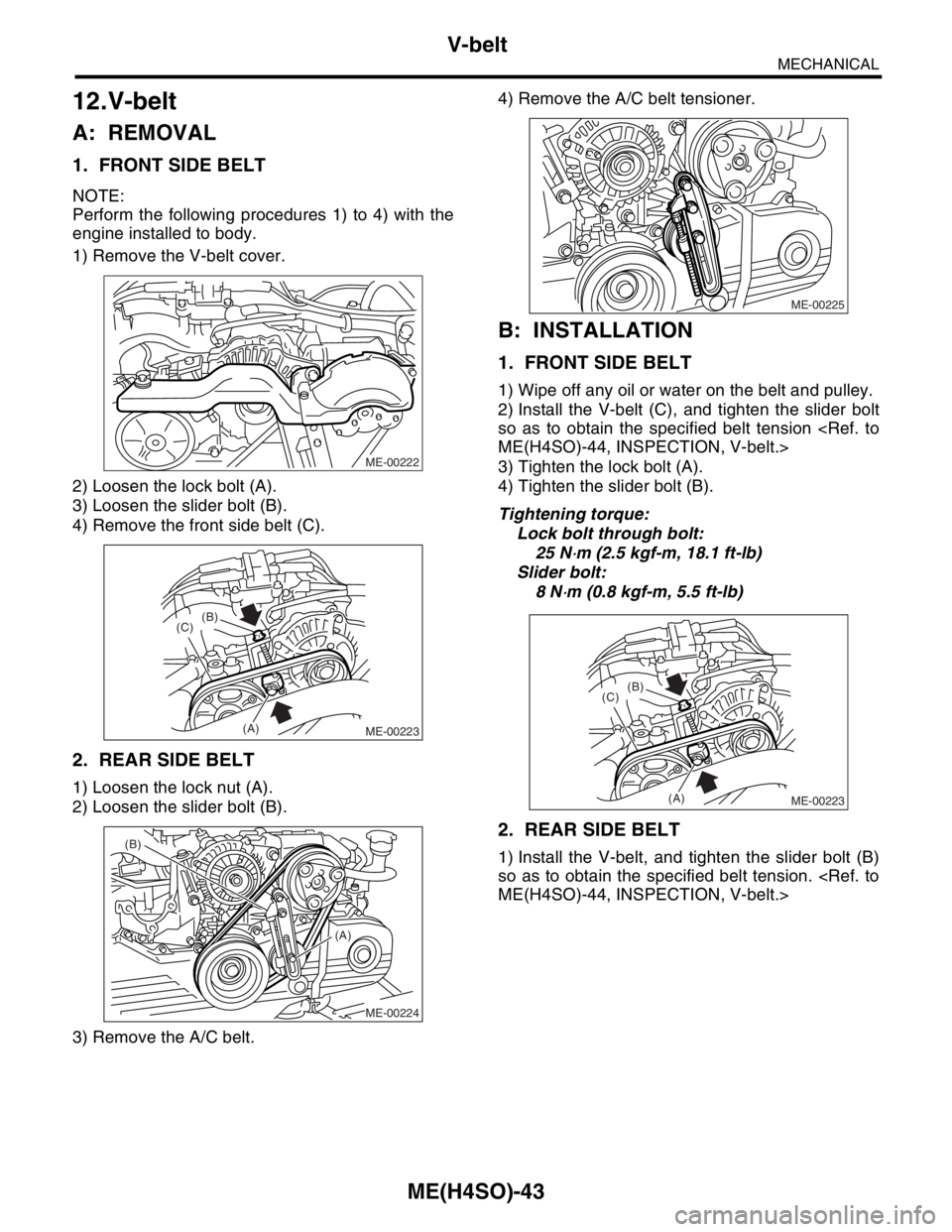
1. FRONT SIDE BELT
NOTE:
Perform the following procedures 1) to 4) with the
engine installed to body.
1) Remove the V-belt cover.
2) Loosen the lock bolt (A).
3) Loosen the slider bolt (B).
4) Remove the front side belt (C).
2. REAR SIDE BELT
1) Loosen the lock nut (A).
2) Loosen the slider bolt (B).
3) Remove the A/C belt.4) Remove the A/C belt tensioner.
B: INSTALLATION
1. FRONT SIDE BELT
1) Wipe off any oil or water on the belt and pulley.
2) Install the V-belt (C), and tighten the slider bolt
so as to obtain the specified belt tension
ME(H4SO)-44, INSPECTION, V-belt.>
3) Tighten the lock bolt (A).
4) Tighten the slider bolt (B).
Tightening torque:
Lock bolt through bolt:
25 N
⋅m (2.5 kgf-m, 18.1 ft-lb)
Slider bolt:
8 N
⋅m (0.8 kgf-m, 5.5 ft-lb)
2. REAR SIDE BELT
1) Install the V-belt, and tighten the slider bolt (B)
so as to obtain the specified belt tension.
ME(H4SO)-44, INSPECTION, V-belt.>
ME-00222
ME-00223
(B)
(C)
(A)
ME-00224
(A) (B)
ME-00225
ME-00223
(B)
(C)
(A)
Page 914 of 2870
ME(H4SO)-45
MECHANICAL
Crank Pulley
13.Crank Pulley
A: REMOVAL
1) Remove the V-belt.
MOVAL, V-belt.>
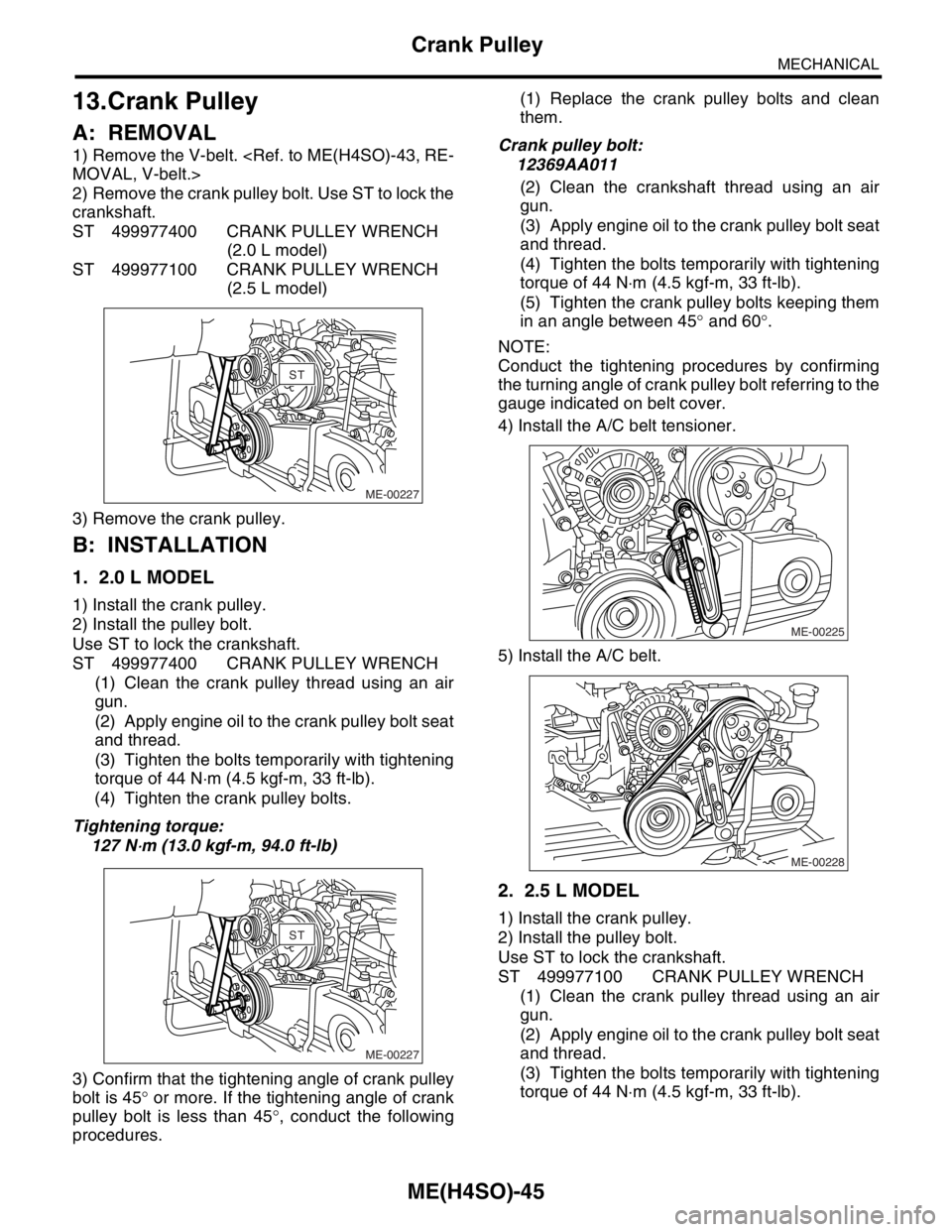
2) Remove the crank pulley bolt. Use ST to lock the
crankshaft.
ST 499977400 CRANK PULLEY WRENCH
(2.0 L model)
ST 499977100 CRANK PULLEY WRENCH
(2.5 L model)
3) Remove the crank pulley.
B: INSTALLATION
1. 2.0 L MODEL
1) Install the crank pulley.
2) Install the pulley bolt.
Use ST to lock the crankshaft.
ST 499977400 CRANK PULLEY WRENCH
(1) Clean the crank pulley thread using an air
gun.
(2) Apply engine oil to the crank pulley bolt seat
and thread.
(3) Tighten the bolts temporarily with tightening
torque of 44 N⋅m (4.5 kgf-m, 33 ft-lb).
(4) Tighten the crank pulley bolts.
Tightening torque:
127 N
⋅m (13.0 kgf-m, 94.0 ft-lb)
3) Confirm that the tightening angle of crank pulley
bolt is 45° or more. If the tightening angle of crank
pulley bolt is less than 45°, conduct the following
procedures.(1) Replace the crank pulley bolts and clean
them.
Crank pulley bolt:
12369AA011
(2) Clean the crankshaft thread using an air
gun.
(3) Apply engine oil to the crank pulley bolt seat
and thread.
(4) Tighten the bolts temporarily with tightening
torque of 44 N⋅m (4.5 kgf-m, 33 ft-lb).
(5) Tighten the crank pulley bolts keeping them
in an angle between 45° and 60°.
NOTE:
Conduct the tightening procedures by confirming
the turning angle of crank pulley bolt referring to the
gauge indicated on belt cover.
4) Install the A/C belt tensioner.
5) Install the A/C belt.
2. 2.5 L MODEL
1) Install the crank pulley.
2) Install the pulley bolt.
Use ST to lock the crankshaft.
ST 499977100 CRANK PULLEY WRENCH
(1) Clean the crank pulley thread using an air
gun.
(2) Apply engine oil to the crank pulley bolt seat
and thread.
(3) Tighten the bolts temporarily with tightening
torque of 44 N⋅m (4.5 kgf-m, 33 ft-lb).
ME-00227
STST
ME-00227
STST
ME-00225
ME-00228
Page 915 of 2870
ME(H4SO)-46
MECHANICAL
Crank Pulley
(4) Tighten the crank pulley bolts.
Tightening torque:
177 N
⋅m (18.0 kgf-m, 130.2 ft-lb)
3) Confirm that the tightening angle of crank pulley
bolt is 65° or more. If the tightening angle of crank
pulley bolt is less than 65°, conduct the following
procedures.
(1) Replace the crank pulley bolts and clean
them.
Crank pulley bolt:
12369AA011
(2) Clean the crankshaft thread using an air
gun.
(3) Apply engine oil to the crank pulley bolt seat
and thread.
(4) Tighten the bolts temporarily with tightening
torque of 44 N⋅m (4.5 kgf-m, 33 ft-lb).
(5) Tighten the crank pulley bolts keeping them
in an angle between 65° and 75°.
NOTE:
Conduct the tightening procedures by confirming
the turning angle of crank pulley bolt referring to the
gauge indicated on belt cover.
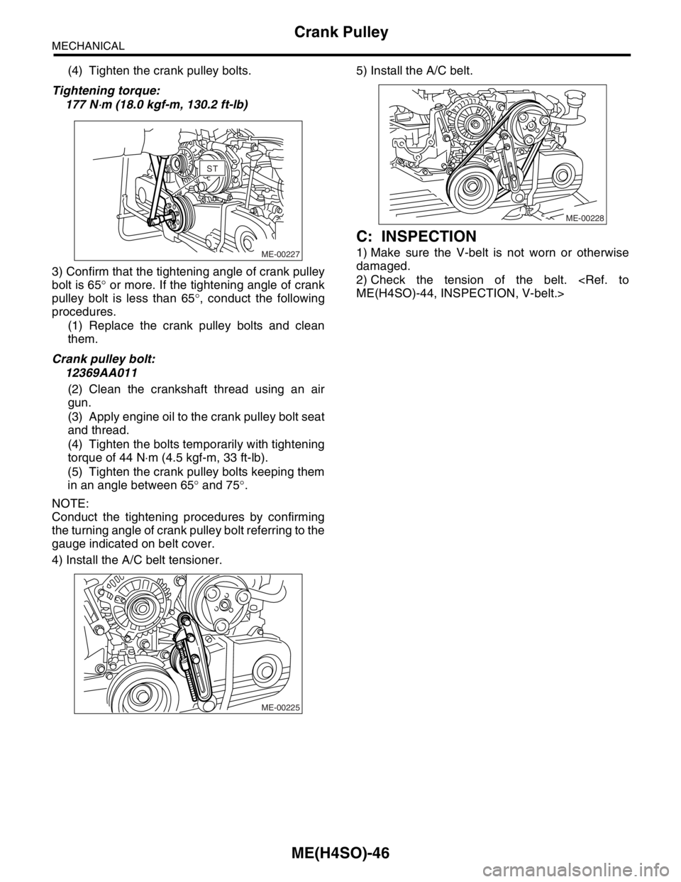
4) Install the A/C belt tensioner.5) Install the A/C belt.
C: INSPECTION
1) Make sure the V-belt is not worn or otherwise
damaged.
2) Check the tension of the belt.
ME(H4SO)-44, INSPECTION, V-belt.>ME-00227
STST
ME-00225
ME-00228
Page 922 of 2870
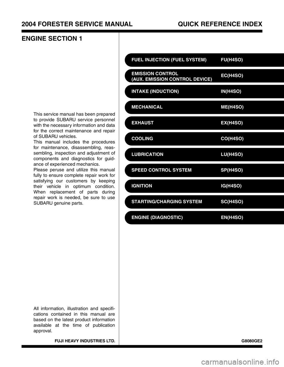
FUJI HEAVY INDUSTRIES LTD. G8080GE2
2004 FORESTER SERVICE MANUAL QUICK REFERENCE INDEX
ENGINE SECTION 1
This service manual has been prepared
to provide SUBARU service personnel
with the necessary information and data
for the correct maintenance and repair
of SUBARU vehicles.
This manual includes the procedures
for maintenance, disassembling, reas-
sembling, inspection and adjustment of
components and diagnostics for guid-
ance of experienced mechanics.
Please peruse and utilize this manual
fully to ensure complete repair work for
satisfying our customers by keeping
their vehicle in optimum condition.
When replacement of parts during
repair work is needed, be sure to use
SUBARU genuine parts.
All information, illustration and specifi-
cations contained in this manual are
based on the latest product information
available at the time of publication
approval.FUEL INJECTION (FUEL SYSTEM) FU(H4SO)
EMISSION CONTROL
(AUX. EMISSION CONTROL DEVICE)EC(H4SO)
INTAKE (INDUCTION) IN(H4SO)
MECHANICAL ME(H4SO)
EXHAUST EX(H4SO)
COOLING CO(H4SO)
LUBRICATION LU(H4SO)
SPEED CONTROL SYSTEM SP(H4SO)
IGNITION IG(H4SO)
STARTING/CHARGING SYSTEM SC(H4SO)
ENGINE (DIAGNOSTIC) EN(H4SO)
Page 923 of 2870

MECHANICAL
ME(H4SO)
Page
1. General Description ....................................................................................2
2. Compression .............................................................................................25
3. Idle Speed .................................................................................................26
4. Ignition Timing ...........................................................................................27
5. Intake Manifold Vacuum............................................................................28
6. Engine Oil Pressure ..................................................................................29
7. Fuel Pressure ............................................................................................30
8. Valve Clearance ........................................................................................31
9. Engine Assembly ......................................................................................34
10. Engine Mounting .......................................................................................41
11. Preparation for Overhaul ...........................................................................42
12. V-belt .........................................................................................................43
13. Crank Pulley ..............................................................................................45
14. Timing Belt Cover......................................................................................47
15. Timing Belt ................................................................................................48
16. Cam Sprocket ...........................................................................................53
17. Crank Sprocket .........................................................................................55
18. Valve Rocker Assembly ............................................................................56
19. Camshaft ...................................................................................................58
20. Cylinder Head ...........................................................................................62
21. Cylinder Block ...........................................................................................69
22. Engine Trouble in General ........................................................................91
23. Engine Noise .............................................................................................96