2004 NISSAN TERRANO oil pressure
[x] Cancel search: oil pressurePage 899 of 1833
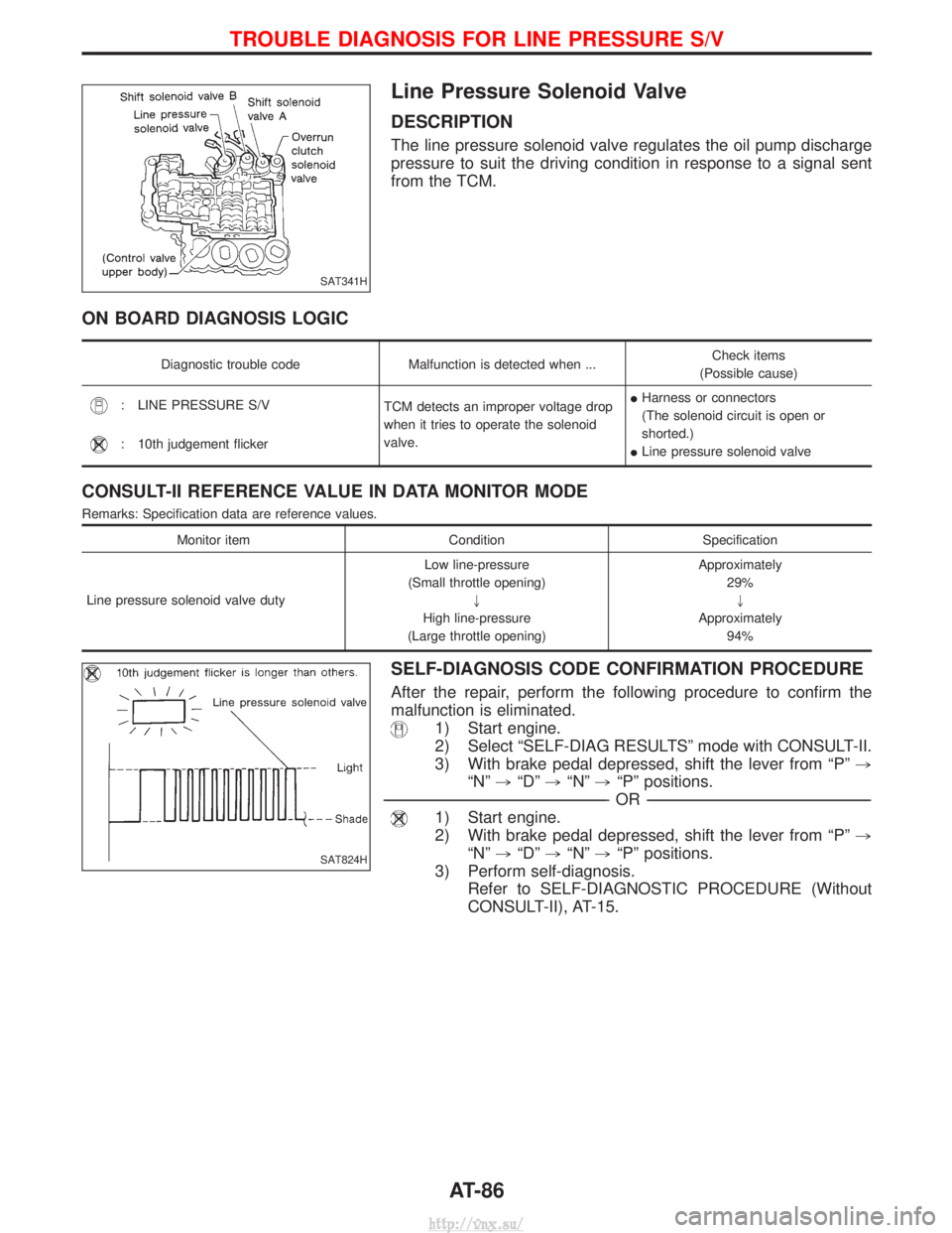
Line Pressure Solenoid Valve
DESCRIPTION
The line pressure solenoid valve regulates the oil pump discharge
pressure to suit the driving condition in response to a signal sent
from the TCM.
ON BOARD DIAGNOSIS LOGIC
Diagnostic trouble codeMalfunction is detected when ... Check items
(Possible cause)
: LINE PRESSURE S/V TCM detects an improper voltage drop
when it tries to operate the solenoid
valve.I
Harness or connectors
(The solenoid circuit is open or
shorted.)
I Line pressure solenoid valve
: 10th judgement flicker
CONSULT-II REFERENCE VALUE IN DATA MONITOR MODE
Remarks: Specification data are reference values.
Monitor item ConditionSpecification
Line pressure solenoid valve duty Low line-pressure
(Small throttle opening) "
High line-pressure
(Large throttle opening) Approximately
29%"
Approximately 94%
SELF-DIAGNOSIS CODE CONFIRMATION PROCEDURE
After the repair, perform the following procedure to confirm the
malfunction is eliminated.
1) Start engine.
2) Select ªSELF-DIAG RESULTSº mode with CONSULT-II.
3) With brake pedal depressed, shift the lever from ªPº ,
ªNº ,ªDº ,ªNº ,ªPº positions.
----------------------------------------------------------------------------------------------------------------------------------------------------------------------------------------------------------------------------------------------------------- -OR------------------------------------------------------------------------------------------------------------------------------------------------------------------------------------------------------------------------------------------------------------
1) Start engine.
2) With brake pedal depressed, shift the lever from ªPº ,
ªNº ,ªDº ,ªNº ,ªPº positions.
3) Perform self-diagnosis. Refer to SELF-DIAGNOSTIC PROCEDURE (Without
CONSULT-II), AT-15.
SAT341H
SAT824H
TROUBLE DIAGNOSIS FOR LINE PRESSURE S/V
AT-86
http://vnx.su/
Page 918 of 1833
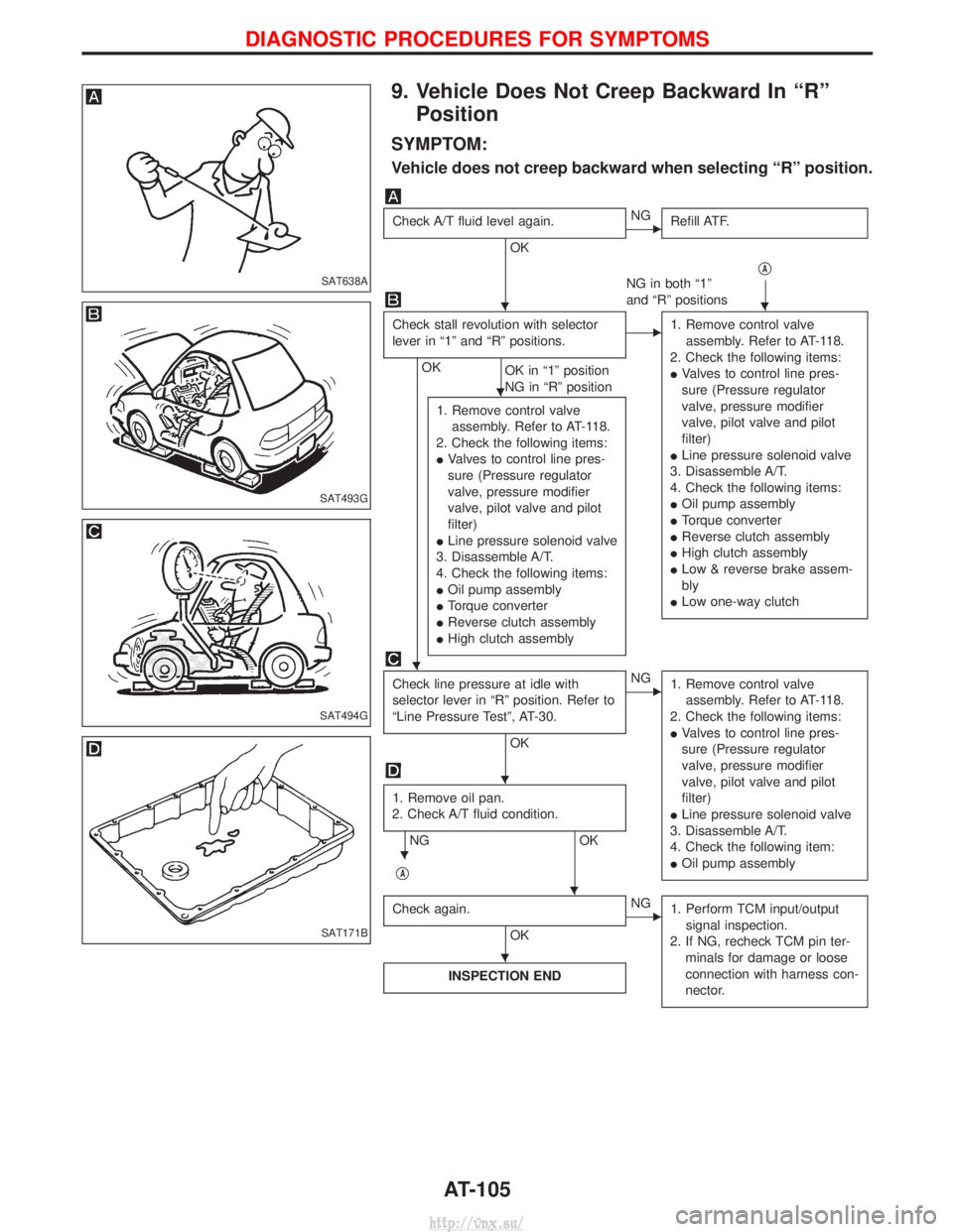
9. Vehicle Does Not Creep Backward In ªRºPosition
SYMPTOM:
Vehicle does not creep backward when selecting ªRº position.
Check A/T fluid level again.
OK
ENG Refill ATF.
qA
NG in both ª1º
and ªRº positions
Check stall revolution with selector
lever in ª1º and ªRº positions.
OK OK in ª1º position
NG in ªRº position
E1. Remove control valve
assembly. Refer to AT-118.
2. Check the following items:
I Valves to control line pres-
sure (Pressure regulator
valve, pressure modifier
valve, pilot valve and pilot
filter)
I Line pressure solenoid valve
3. Disassemble A/T.
4. Check the following items:
I Oil pump assembly
I Torque converter
I Reverse clutch assembly
I High clutch assembly
I Low & reverse brake assem-
bly
I Low one-way clutch
1. Remove control valve
assembly. Refer to AT-118.
2. Check the following items:
I Valves to control line pres-
sure (Pressure regulator
valve, pressure modifier
valve, pilot valve and pilot
filter)
I Line pressure solenoid valve
3. Disassemble A/T.
4. Check the following items:
I Oil pump assembly
I Torque converter
I Reverse clutch assembly
I High clutch assembly
Check line pressure at idle with
selector lever in ªRº position. Refer to
ªLine Pressure Testº, AT-30.
OK
ENG
1. Remove control valve
assembly. Refer to AT-118.
2. Check the following items:
I Valves to control line pres-
sure (Pressure regulator
valve, pressure modifier
valve, pilot valve and pilot
filter)
I Line pressure solenoid valve
3. Disassemble A/T.
4. Check the following item:
I Oil pump assembly
1. Remove oil pan.
2. Check A/T fluid condition.
NG OK
q
A
Check again.
OK
ENG 1. Perform TCM input/output
signal inspection.
2. If NG, recheck TCM pin ter- minals for damage or loose
connection with harness con-
nector.
INSPECTION END
SAT638A
SAT493G
SAT494G
SAT171B
HH
H
H
H
H
H
H
DIAGNOSTIC PROCEDURES FOR SYMPTOMS
AT-105
http://vnx.su/
Page 919 of 1833
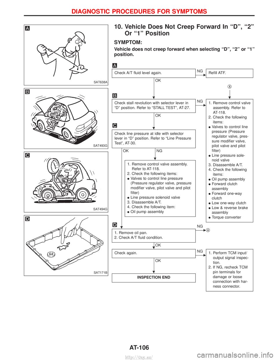
10. Vehicle Does Not Creep Forward In ªDº, ª2ºOr ª1º Position
SYMPTOM:
Vehicle does not creep forward when selecting ªDº, ª2º or ª1º
position.
Check A/T fluid level again.
OK
ENG Refill ATF.
qA
Check stall revolution with selector lever in
ªDº position. Refer to ªSTALL TESTº, AT-27.
OK
ENG1. Remove control valve
assembly. Refer to
AT-118.
2. Check the following items:
I Valves to control line
pressure (Pressure
regulator valve, pres-
sure modifier valve,
pilot valve and pilot
filter)
I Line pressure sole-
noid valve
3. Disassemble A/T.
4. Check the following items:
I Oil pump assembly
I Forward clutch
assembly
I Forward one-way
clutch
I Low one-way clutch
I Low & reverse brake
assembly
I Torque converter
Check line pressure at idle with selector
lever in ªDº position. Refer to ªLine Pressure
Testº, AT-30.
OK NG
1. Remove control valve assembly. Refer to AT-118.
2. Check the following items:
I Valves to control line pressure
(Pressure regulator valve, pressure
modifier valve, pilot valve and pilot
filter)
I Line pressure solenoid valve
3. Disassemble A/T.
4. Check the following item:
I Oil pump assembly
1. Remove oil pan.
2. Check A/T fluid condition.
OK
ENG qA
Check again.
OK
ENG 1. Perform TCM input/
output signal inspec-
tion.
2. If NG, recheck TCM pin terminals for
damage or loose
connection with har-
ness connector.
INSPECTION END
SAT638A
SAT493G
SAT494G
SAT171B
HH
H
H
H
HH
H
DIAGNOSTIC PROCEDURES FOR SYMPTOMS
AT-106
http://vnx.su/
Page 920 of 1833
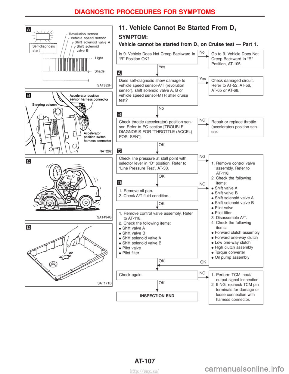
11. Vehicle Cannot Be Started From D1
SYMPTOM:
Vehicle cannot be started from D1on Cruise test Ð Part 1.
Is 9. Vehicle Does Not Creep Backward In
ªRº Position OK?
Ye s
ENoGo to 9. Vehicle Does Not
Creep Backward In ªRº
Position, AT-105.
Does self-diagnosis show damage to
vehicle speed sensor×A/T (revolution
sensor), shift solenoid valve A, B or
vehicle speed sensor×MTR after cruise
test?
No
EYe sCheck damaged circuit.
Refer to AT-52, AT-56,
AT-65 or AT-68.
Check throttle (accelerator) position sen-
sor. Refer to EC section [TROUBLE
DIAGNOSIS FOR ªTHROTTLE (ACCEL)
POSI SENº].
OK
ENGRepair or replace throttle
(accelerator) position sen-
sor.
Check line pressure at stall point with
selector lever in ªDº position. Refer to
ªLine Pressure Testº, AT-30.
OK
ENG
1. Remove control valveassembly. Refer to
AT-118.
2. Check the following items:
I Shift valve A
I Shift valve B
I Shift solenoid valve A
I Shift solenoid valve B
I Pilot valve
I Pilot filter
3. Disassemble A/T.
4. Check the following items:
I Forward clutch assembly
I Forward one-way clutch
I Low one-way clutch
I High clutch assembly
I Torque converter
I Oil pump assembly
1. Remove oil pan.
2. Check A/T fluid condition.
OK
ENG
1. Remove control valve assembly. Refer to AT-118.
2. Check the following items:
I Shift valve A
I Shift valve B
I Shift solenoid valve A
I Shift solenoid valve B
I Pilot valve
I Pilot filter
OKFOK
Check again.
OK
ENG 1. Perform TCM input/
output signal inspection.
2. If NG, recheck TCM pin terminals for damage or
loose connection with
harness connector.
INSPECTION END
SAT832H
NAT262
SAT494G
SAT171B
H
H
H
H
H
HH
H
DIAGNOSTIC PROCEDURES FOR SYMPTOMS
AT-107
http://vnx.su/
Page 942 of 1833
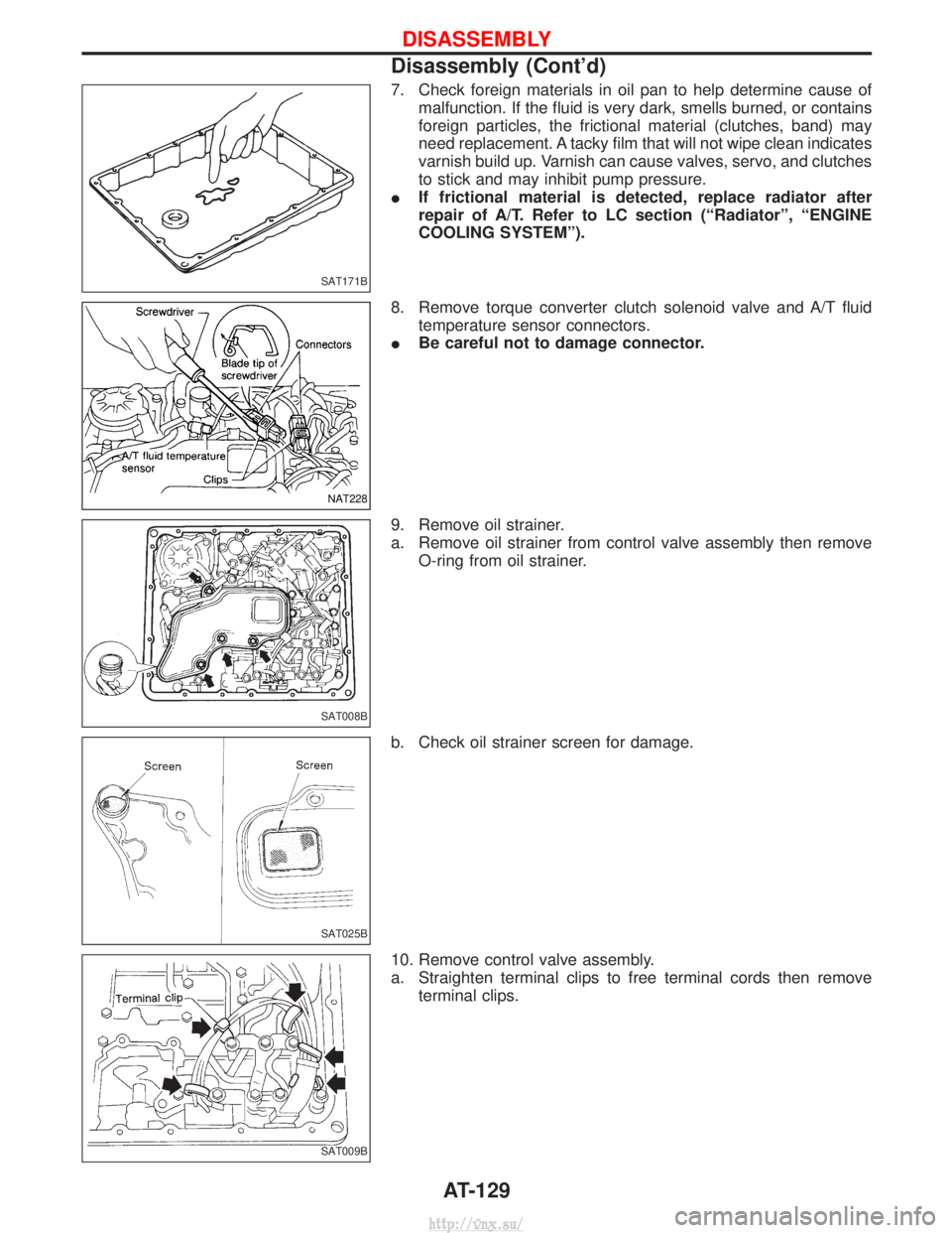
7. Check foreign materials in oil pan to help determine cause ofmalfunction. If the fluid is very dark, smells burned, or contains
foreign particles, the frictional material (clutches, band) may
need replacement. A tacky film that will not wipe clean indicates
varnish build up. Varnish can cause valves, servo, and clutches
to stick and may inhibit pump pressure.
I If frictional material is detected, replace radiator after
repair of A/T. Refer to LC section (ªRadiatorº, ªENGINE
COOLING SYSTEMº).
8. Remove torque converter clutch solenoid valve and A/T fluid temperature sensor connectors.
I Be careful not to damage connector.
9. Remove oil strainer.
a. Remove oil strainer from control valve assembly then remove O-ring from oil strainer.
b. Check oil strainer screen for damage.
10. Remove control valve assembly.
a. Straighten terminal clips to free terminal cords then remove terminal clips.
SAT171B
NAT228
SAT008B
SAT025B
SAT009B
DISASSEMBLY
Disassembly (Cont'd)
AT-129
http://vnx.su/
Page 959 of 1833
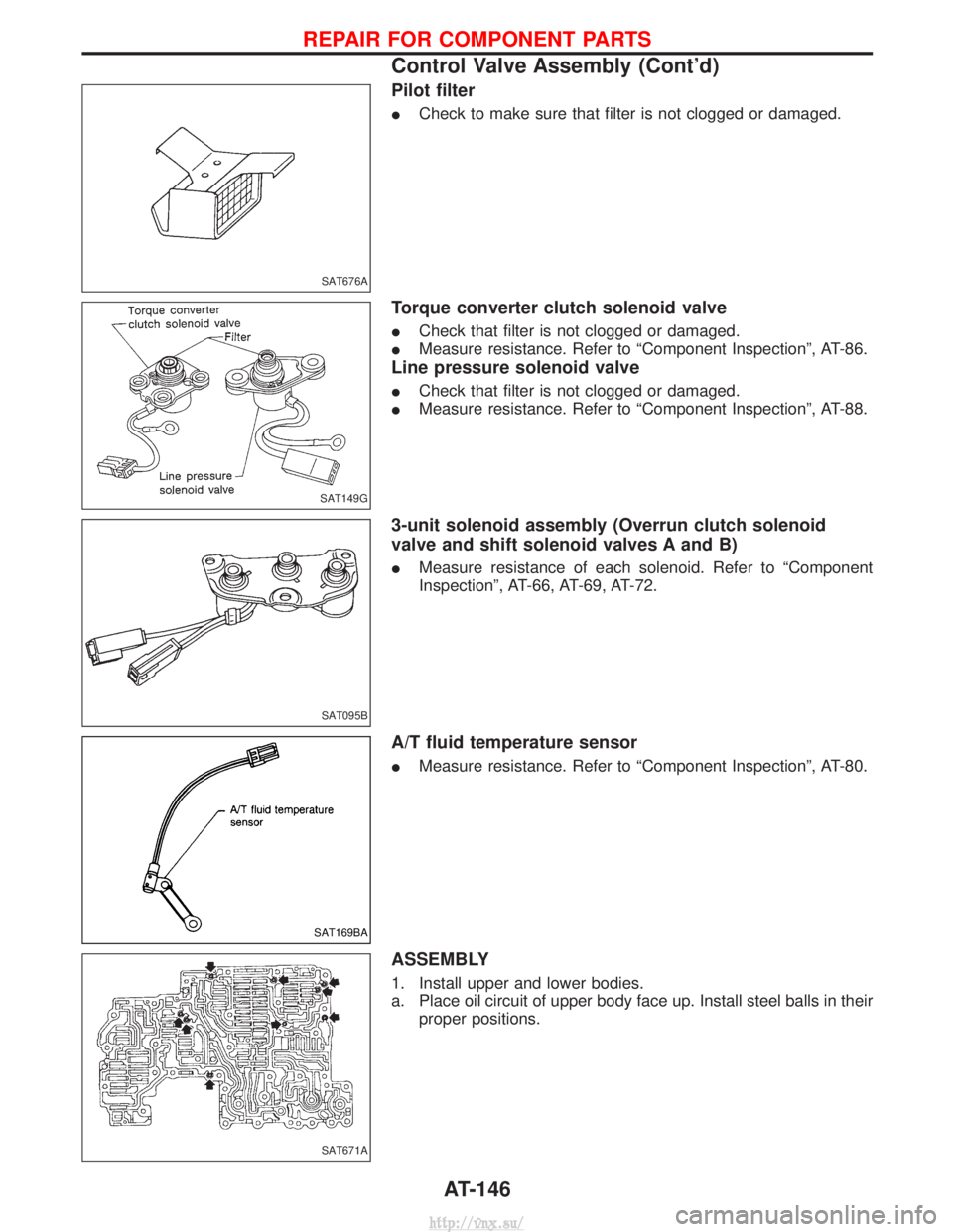
Pilot filter
ICheck to make sure that filter is not clogged or damaged.
Torque converter clutch solenoid valve
ICheck that filter is not clogged or damaged.
I Measure resistance. Refer to ªComponent Inspectionº, AT-86.
Line pressure solenoid valve
ICheck that filter is not clogged or damaged.
I Measure resistance. Refer to ªComponent Inspectionº, AT-88.
3-unit solenoid assembly (Overrun clutch solenoid
valve and shift solenoid valves A and B)
IMeasure resistance of each solenoid. Refer to ªComponent
Inspectionº, AT-66, AT-69, AT-72.
A/T fluid temperature sensor
IMeasure resistance. Refer to ªComponent Inspectionº, AT-80.
ASSEMBLY
1. Install upper and lower bodies.
a. Place oil circuit of upper body face up. Install steel balls in their
proper positions.
SAT676A
SAT149G
SAT095B
SAT169BA
SAT671A
REPAIR FOR COMPONENT PARTS
Control Valve Assembly (Cont'd)
AT-146
http://vnx.su/
Page 1095 of 1833
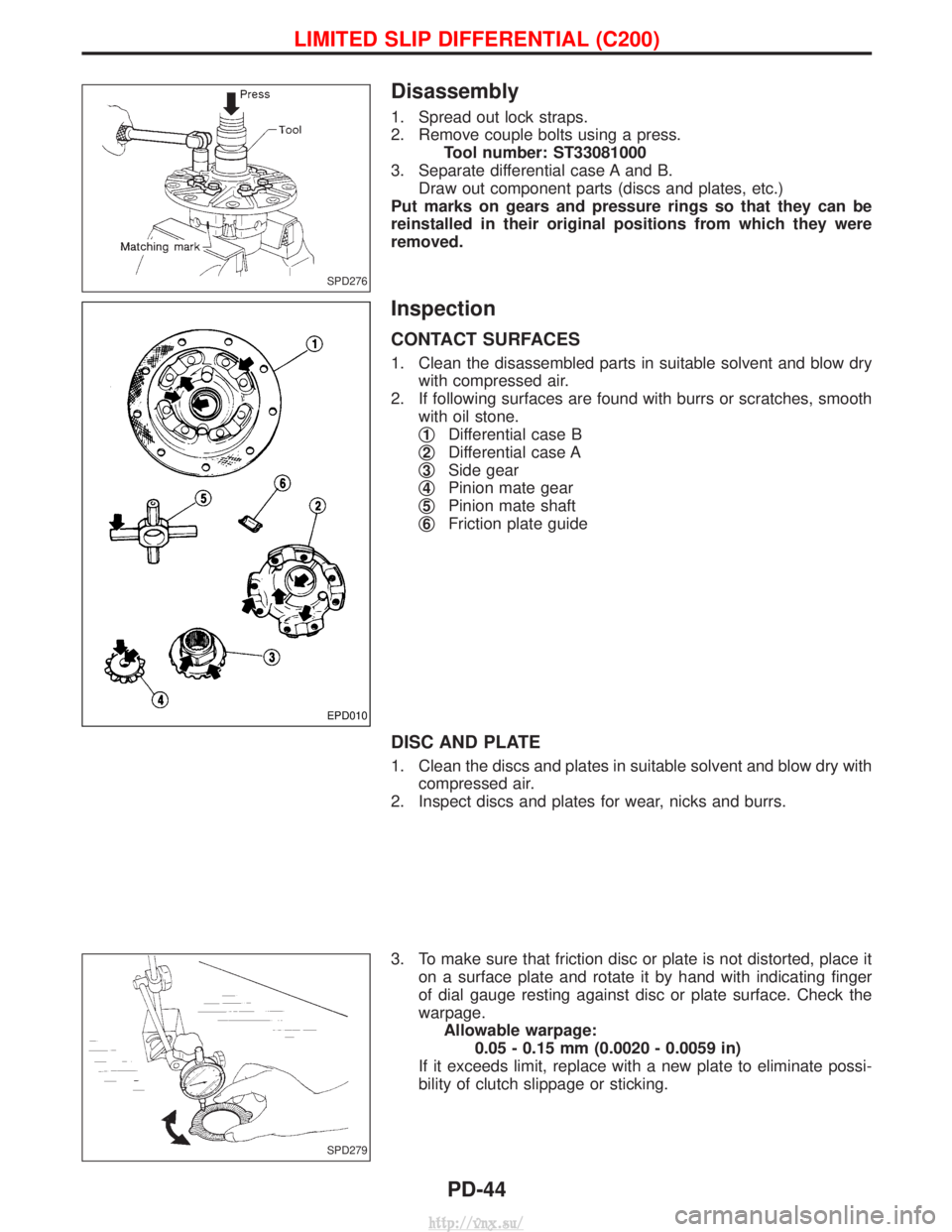
Disassembly
1. Spread out lock straps.
2. Remove couple bolts using a press.Tool number: ST33081000
3. Separate differential case A and B. Draw out component parts (discs and plates, etc.)
Put marks on gears and pressure rings so that they can be
reinstalled in their original positions from which they were
removed.
Inspection
CONTACT SURFACES
1. Clean the disassembled parts in suitable solvent and blow dry with compressed air.
2. If following surfaces are found with burrs or scratches, smooth with oil stone.
q
1Differential case B
q
2Differential case A
q
3Side gear
q
4Pinion mate gear
q
5Pinion mate shaft
q
6Friction plate guide
DISC AND PLATE
1. Clean the discs and plates in suitable solvent and blow dry with
compressed air.
2. Inspect discs and plates for wear, nicks and burrs.
3. To make sure that friction disc or plate is not distorted, place it on a surface plate and rotate it by hand with indicating finger
of dial gauge resting against disc or plate surface. Check the
warpage.Allowable warpage: 0.05 - 0.15 mm (0.0020 - 0.0059 in)
If it exceeds limit, replace with a new plate to eliminate possi-
bility of clutch slippage or sticking.
SPD276
EPD010
SPD279
LIMITED SLIP DIFFERENTIAL (C200)
PD-44
http://vnx.su/
Page 1172 of 1833
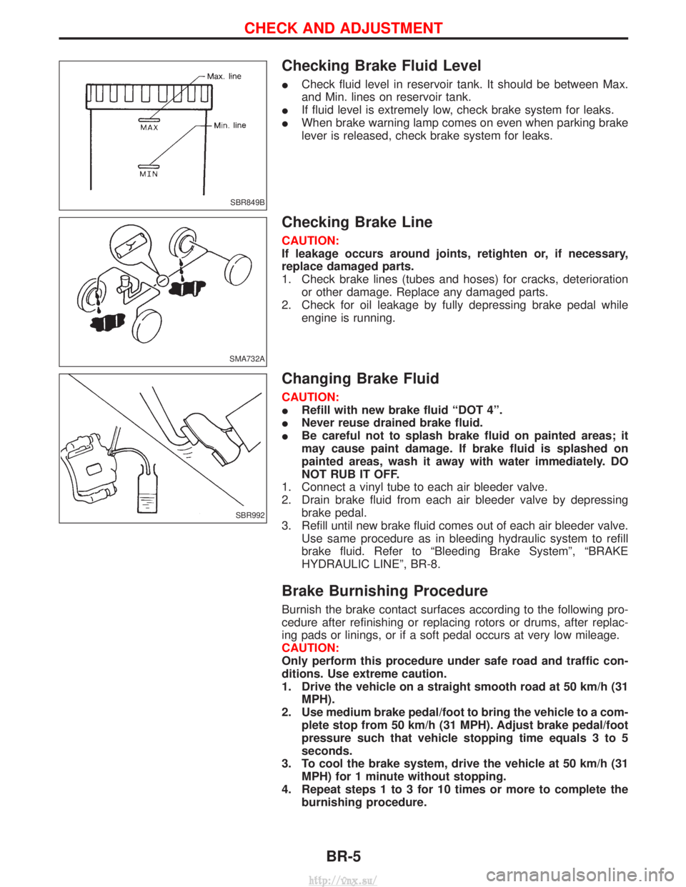
Checking Brake Fluid Level
ICheck fluid level in reservoir tank. It should be between Max.
and Min. lines on reservoir tank.
I If fluid level is extremely low, check brake system for leaks.
I When brake warning lamp comes on even when parking brake
lever is released, check brake system for leaks.
Checking Brake Line
CAUTION:
If leakage occurs around joints, retighten or, if necessary,
replace damaged parts.
1. Check brake lines (tubes and hoses) for cracks, deterioration
or other damage. Replace any damaged parts.
2. Check for oil leakage by fully depressing brake pedal while engine is running.
Changing Brake Fluid
CAUTION:
IRefill with new brake fluid ªDOT 4º.
I Never reuse drained brake fluid.
I Be careful not to splash brake fluid on painted areas; it
may cause paint damage. If brake fluid is splashed on
painted areas, wash it away with water immediately. DO
NOT RUB IT OFF.
1. Connect a vinyl tube to each air bleeder valve.
2. Drain brake fluid from each air bleeder valve by depressing brake pedal.
3. Refill until new brake fluid comes out of each air bleeder valve. Use same procedure as in bleeding hydraulic system to refill
brake fluid. Refer to ªBleeding Brake Systemº, ªBRAKE
HYDRAULIC LINEº, BR-8.
Brake Burnishing Procedure
Burnish the brake contact surfaces according to the following pro-
cedure after refinishing or replacing rotors or drums, after replac-
ing pads or linings, or if a soft pedal occurs at very low mileage.
CAUTION:
Only perform this procedure under safe road and traffic con-
ditions. Use extreme caution.
1. Drive the vehicle on a straight smooth road at 50 km/h (31MPH).
2. Use medium brake pedal/foot to bring the vehicle to a com- plete stop from 50 km/h (31 MPH). Adjust brake pedal/foot
pressure such that vehicle stopping time equals 3 to 5
seconds.
3. To cool the brake system, drive the vehicle at 50 km/h (31 MPH) for 1 minute without stopping.
4. Repeat steps 1 to 3 for 10 times or more to complete the burnishing procedure.
SBR849B
SMA732A
SBR992
CHECK AND ADJUSTMENT
BR-5
http://vnx.su/