2004 NISSAN TERRANO oil pressure
[x] Cancel search: oil pressurePage 1431 of 1833
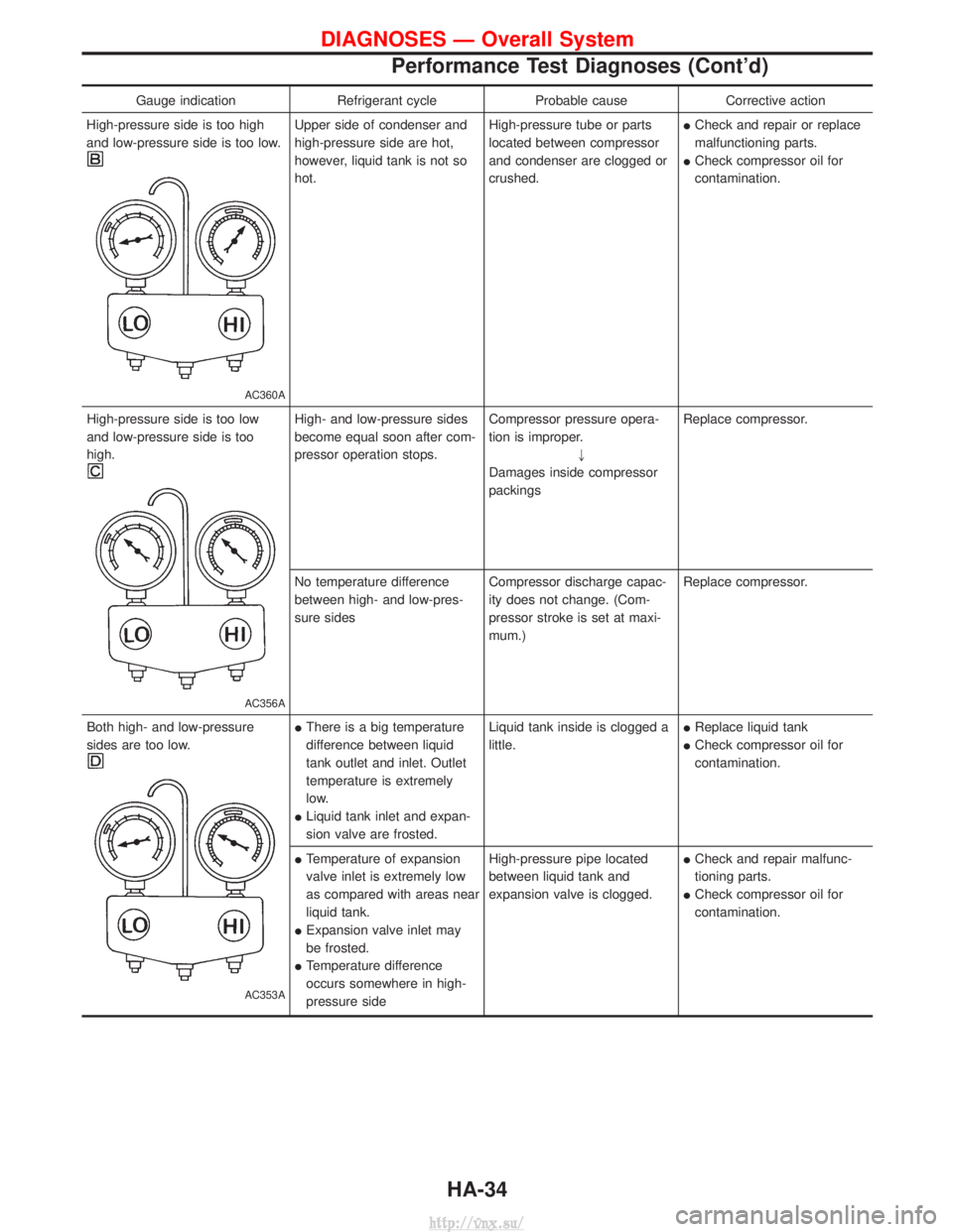
Gauge indicationRefrigerant cycleProbable causeCorrective action
High-pressure side is too high
and low-pressure side is too low.
AC360A
Upper side of condenser and
high-pressure side are hot,
however, liquid tank is not so
hot. High-pressure tube or parts
located between compressor
and condenser are clogged or
crushed.I
Check and repair or replace
malfunctioning parts.
I Check compressor oil for
contamination.
High-pressure side is too low
and low-pressure side is too
high.
AC356A
High- and low-pressure sides
become equal soon after com-
pressor operation stops. Compressor pressure opera-
tion is improper.
"
Damages inside compressor
packings Replace compressor.
No temperature difference
between high- and low-pres-
sure sides Compressor discharge capac-
ity does not change. (Com-
pressor stroke is set at maxi-
mum.)Replace compressor.
Both high- and low-pressure
sides are too low.
AC353A
I There is a big temperature
difference between liquid
tank outlet and inlet. Outlet
temperature is extremely
low.
I Liquid tank inlet and expan-
sion valve are frosted. Liquid tank inside is clogged a
little.
I
Replace liquid tank
I Check compressor oil for
contamination.
I Temperature of expansion
valve inlet is extremely low
as compared with areas near
liquid tank.
I Expansion valve inlet may
be frosted.
I Temperature difference
occurs somewhere in high-
pressure side High-pressure pipe located
between liquid tank and
expansion valve is clogged.
I
Check and repair malfunc-
tioning parts.
I Check compressor oil for
contamination.
DIAGNOSES Ð Overall System
Performance Test Diagnoses (Cont'd)
HA-34
http://vnx.su/
Page 1432 of 1833
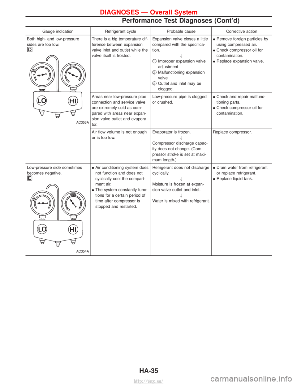
Gauge indicationRefrigerant cycleProbable causeCorrective action
Both high- and low-pressure
sides are too low.
AC353A
There is a big temperature dif-
ference between expansion
valve inlet and outlet while the
valve itself is frosted. Expansion valve closes a little
compared with the specifica-
tion.
"
q
1Improper expansion valve
adjustment
q
2Malfunctioning expansion
valve
q
3Outlet and inlet may be
clogged. I
Remove foreign particles by
using compressed air.
I Check compressor oil for
contamination.
I Replace expansion valve.
Areas near low-pressure pipe
connection and service valve
are extremely cold as com-
pared with areas near expan-
sion valve outlet and evapora-
tor. Low-pressure pipe is clogged
or crushed.
I
Check and repair malfunc-
tioning parts.
I Check compressor oil for
contamination.
Air flow volume is not enough
or is too low. Evaporator is frozen.
"
Compressor discharge capac-
ity does not change. (Com-
pressor stroke is set at maxi-
mum length.) Replace compressor.
Low-pressure side sometimes
becomes negative.
AC354A
I Air conditioning system does
not function and does not
cyclically cool the compart-
ment air.
I The system constantly func-
tions for a certain period of
time after compressor is
stopped and restarted. Refrigerant does not discharge
cyclically.
"
Moisture is frozen at expan-
sion valve outlet and inlet. "
Water is mixed with refrigerant. I
Drain water from refrigerant
or replace refrigerant.
I Replace liquid tank.
DIAGNOSES Ð Overall System
Performance Test Diagnoses (Cont'd)
HA-35
http://vnx.su/
Page 1433 of 1833
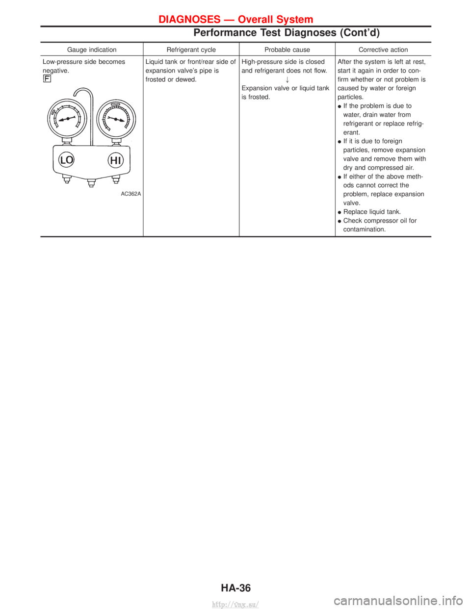
Gauge indicationRefrigerant cycleProbable causeCorrective action
Low-pressure side becomes
negative.
AC362A
Liquid tank or front/rear side of
expansion valve's pipe is
frosted or dewed. High-pressure side is closed
and refrigerant does not flow.
"
Expansion valve or liquid tank
is frosted. After the system is left at rest,
start it again in order to con-
firm whether or not problem is
caused by water or foreign
particles.
I
If the problem is due to
water, drain water from
refrigerant or replace refrig-
erant.
I If it is due to foreign
particles, remove expansion
valve and remove them with
dry and compressed air.
I If either of the above meth-
ods cannot correct the
problem, replace expansion
valve.
I Replace liquid tank.
I Check compressor oil for
contamination.
DIAGNOSES Ð Overall System
Performance Test Diagnoses (Cont'd)
HA-36
http://vnx.su/
Page 1435 of 1833
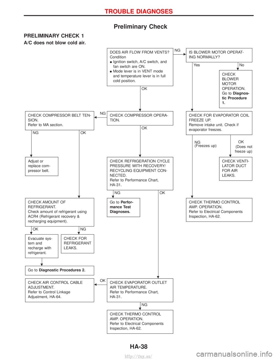
Preliminary Check
PRELIMINARY CHECK 1
A/C does not blow cold air.
DOES AIR FLOW FROM VENTS?
Condition
IIgnition switch, A/C switch, and
fan switch are ON.
I Mode lever is in VENT mode
and temperature lever is in full
cold position.
OK
ENG
IS BLOWER MOTOR OPERAT-
ING NORMALLY?
Ye s N o
CHECK
BLOWER
MOTOR
OPERATION.
Go to Diagnos-
tic Procedure
1.
CHECK COMPRESSOR BELT TEN-
SION.
Refer to MA section.
NG OK
FNG
CHECK COMPRESSOR OPERA-
TION.
OK CHECK FOR EVAPORATOR COIL
FREEZE UP.
Remove intake unit. Check if
evaporator freezes.
NG
(Freezes up)
OK
(Does not
freeze up)
Adjust or
replace com-
pressor belt.
CHECK REFRIGERATION CYCLE
PRESSURE WITH RECOVERY/
RECYCLING EQUIPMENT CON-
NECTED.
Refer to Performance Chart,
HA-31.
NG OK CHECK VENTI-
LATOR DUCT
FOR AIR
LEAKS.
CHECK AMOUNT OF
REFRIGERANT.
Check amount of refrigerant using
ACR4 (Refrigerant recovery &
recharging equipment).
OK
NGGo to
Perfor-
mance Test
Diagnoses.
CHECK THERMO CONTROL
AMP. OPERATION.
Refer to Electrical Components
Inspection, HA-62.
Evacuate sys-
tem and
recharge with
refrigerant.CHECK FOR
REFRIGERANT
LEAKS.
Go to Diagnostic Procedures 2.
CHECK AIR CONTROL CABLE
ADJUSTMENT.
Refer to Control Linkage
Adjustment, HA-64.FOK
CHECK EVAPORATOR OUTLET
AIR TEMPERATURE.
Refer to Performance Chart,
HA-31.
NG
CHECK THERMO CONTROL
AMP. OPERATION.
Refer to Electrical Components
Inspection, HA-62.
H
HH
HHH
HHH
HH
H
H
H
TROUBLE DIAGNOSES
HA-38
http://vnx.su/
Page 1454 of 1833
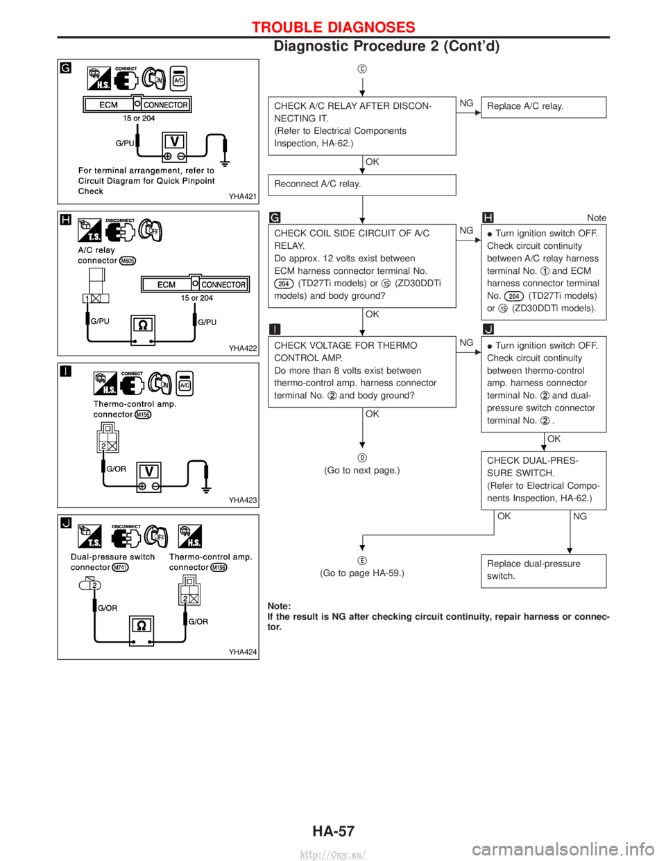
qC
CHECK A/C RELAY AFTER DISCON-
NECTING IT.
(Refer to Electrical Components
Inspection, HA-62.)
OK
ENGReplace A/C relay.
Reconnect A/C relay.
Note
CHECK COIL SIDE CIRCUIT OF A/C
RELAY.
Do approx. 12 volts exist between
ECM harness connector terminal No.
204(TD27Ti models) or q15(ZD30DDTi
models) and body ground?
OK
ENG ITurn ignition switch OFF.
Check circuit continuity
between A/C relay harness
terminal No. q
1and ECM
harness connector terminal
No.
204(TD27Ti models)
or q
15(ZD30DDTi models).
CHECK VOLTAGE FOR THERMO
CONTROL AMP.
Do more than 8 volts exist between
thermo-control amp. harness connector
terminal No. q
2and body ground?
OK
ENG
ITurn ignition switch OFF.
Check circuit continuity
between thermo-control
amp. harness connector
terminal No. q
2and dual-
pressure switch connector
terminal No. q
2.
OK
q
D
(Go to next page.) CHECK DUAL-PRES-
SURE SWITCH.
(Refer to Electrical Compo-
nents Inspection, HA-62.)
NGOK
q
E
(Go to page HA-59.) Replace dual-pressure
switch.
Note:
If the result is NG after checking circuit continuity, repair harness or connec-
tor.
YHA421
YHA422
YHA423
YHA424
H
H
H
H
HH
HH
TROUBLE DIAGNOSES
Diagnostic Procedure 2 (Cont'd)
HA-57
http://vnx.su/
Page 1459 of 1833
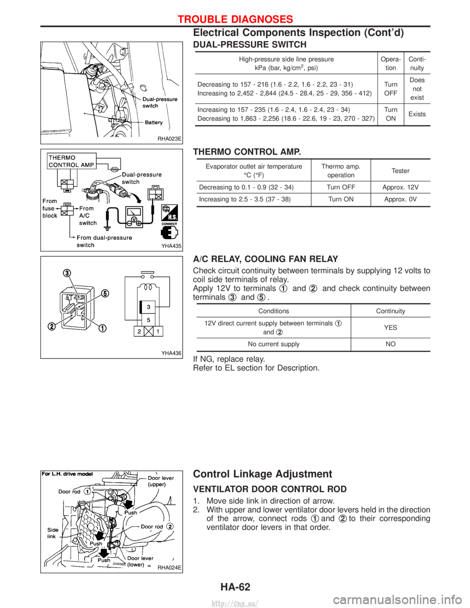
DUAL-PRESSURE SWITCH
High-pressure side line pressurekPa (bar, kg/cm2, psi) Opera-
tion Conti-
nuity
Decreasing to 157 - 216 (1.6 - 2.2, 1.6 - 2.2, 23 - 31)
Increasing to 2,452 - 2,844 (24.5 - 28.4, 25 - 29, 356 - 412) Turn
OFF Does
not
exist
Increasing to 157 - 235 (1.6 - 2.4, 1.6 - 2.4, 23 - 34)
Decreasing to 1,863 - 2,256 (18.6 - 22.6, 19 - 23, 270 - 327) Turn
ON Exists
THERMO CONTROL AMP.
Evaporator outlet air temperature
ÉC (ÉF) Thermo amp.
operation Tester
Decreasing to 0.1 - 0.9 (32 - 34) Turn OFF Approx. 12V
Increasing to 2.5 - 3.5 (37 - 38) Turn ON Approx. 0V
A/C RELAY, COOLING FAN RELAY
Check circuit continuity between terminals by supplying 12 volts to
coil side terminals of relay.
Apply 12V to terminals q
1andq2and check continuity between
terminals q
3andq5.
Conditions
Continuity
12V direct current supply between terminals q
1
andq2YES
No current supply NO
If NG, replace relay.
Refer to EL section for Description.
Control Linkage Adjustment
VENTILATOR DOOR CONTROL ROD
1. Move side link in direction of arrow.
2. With upper and lower ventilator door levers held in the direction of the arrow, connect rods q
1andq2to their corresponding
ventilator door levers in that order.
RHA023E
YHA435
YHA436
RHA024E
TROUBLE DIAGNOSES
Electrical Components Inspection (Cont'd)
HA-62
http://vnx.su/
Page 1493 of 1833
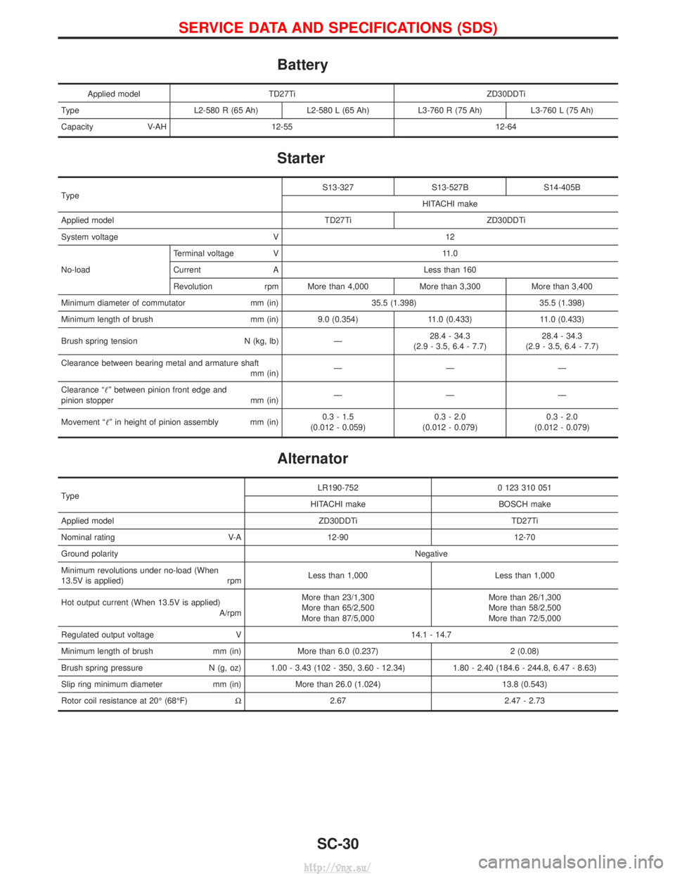
Battery
Applied modelTD27Ti ZD30DDTi
Type L2-580 R (65 Ah)L2-580 L (65 Ah)L3-760 R (75 Ah) L3-760 L (75 Ah)
Capacity V-AH 12-55 12-64
Starter
Type S13-327 S13-527B S14-405B
HITACHI make
Applied model TD27Ti ZD30DDTi
System voltage V 12
No-load Terminal voltage V 11.0
Current A Less than 160
Revolution rpm More than 4,000 More than 3,300 More than 3,400
Minimum diameter of commutator mm (in) 35.5 (1.398) 35.5 (1.398)
Minimum length of brush mm (in) 9.0 (0.354) 11.0 (0.433) 11.0 (0.433)
Brush spring tension N (kg, lb) Ð 28.4 - 34.3
(2.9 - 3.5, 6.4 - 7.7) 28.4 - 34.3
(2.9 - 3.5, 6.4 - 7.7)
Clearance between bearing metal and armature shaft mm (in)ÐÐÐ
Clearance ªº between pinion front edge and
pinion stopper mm (in) ÐÐÐ
Movement ªº in height of pinion assembly mm (in) 0.3 - 1.5
(0.012 - 0.059) 0.3 - 2.0
(0.012 - 0.079) 0.3 - 2.0
(0.012 - 0.079)
Alternator
Type LR190-752 0 123 310 051
HITACHI make BOSCH make
Applied model ZD30DDTi TD27Ti
Nominal rating V-A 12-90 12-70
Ground polarity Negative
Minimum revolutions under no-load (When
13.5V is applied) rpm Less than 1,000 Less than 1,000
Hot output current (When 13.5V is applied) A/rpmMore than 23/1,300
More than 65/2,500
More than 87/5,000 More than 26/1,300
More than 58/2,500
More than 72/5,000
Regulated output voltage V 14.1 - 14.7
Minimum length of brush mm (in) More than 6.0 (0.237) 2 (0.08)
Brush spring pressure N (g, oz) 1.00 - 3.43 (102 - 350, 3.60 - 12.34) 1.80 - 2.40 (184.6 - 244.8, 6.47 - 8.63)
Slip ring minimum diameter mm (in) More than 26.0 (1.024) 13.8 (0.543)
Rotor coil resistance at 20É (68ÉF) W2.67 2.47 - 2.73
SERVICE DATA AND SPECIFICATIONS (SDS)
SC-30
http://vnx.su/
Page 1495 of 1833
Oil Pressure Switch Check ...................................... 110
Wiring Diagram - CHIME - ...................................... 111
WIPER AND WASHER ................................................ 112
Wiring Diagram - WIPER - ...................................... 112
Wiring Diagram - WIP/R -........................................ 114
Installation ................................................................ 116
Washer Nozzle Adjustment ..................................... 117
Check Valve ............................................................. 117
Wiring Diagram - HLC - ........................................... 118
HORN, CIGARETTE LIGHTER AND CLOCK ............122
Wiring Diagram - HORN - .......................................122
Wiring Diagram - CIGAR -.......................................123
Wiring Diagram - CLOCK -......................................124
REAR WINDOW DEFOGGER AND DOOR
MIRROR DEFOGGER .................................................125
System Description ..................................................125
Wiring Diagram - DEF - ...........................................126
Trouble Diagnoses...................................................128
Filament Check ........................................................132
Filament Repair .......................................................133
AUDIO ........................................................................\
..134
System Description ..................................................134
Schematic ................................................................136
Wiring Diagram - AUDIO - .......................................138
Wiring Diagram - REMOTE -...................................145
Trouble Diagnoses...................................................147
Inspection.................................................................149
Location of Roof Mounted Antenna .........................150
HEATED SEAT ............................................................151
Wiring Diagram - HSEAT - ......................................151
SUNROOF ....................................................................153
Wiring Diagram - SROOF - .....................................153
DOOR MIRROR ...........................................................154
Wiring Diagram - MIRROR - ...................................154
POWER WINDOW .......................................................156
System Description ..................................................156
Schematic ................................................................158
Wiring Diagram - WINDOW - ..................................159
Trouble Diagnoses...................................................162
POWER DOOR LOCK .................................................163
System Description ..................................................163
Schematic ................................................................164
Wiring Diagram - D/LOCK -.....................................166
Trouble Diagnoses...................................................171
POWER DOOR LOCK - SUPER LOCK - ...................179
Component Parts Location ......................................179
System Description ..................................................180
Schematic ................................................................182 Wiring Diagram - S/LOCK - .....................................184
Trouble Diagnoses...................................................192
MULTI-REMOTE CONTROL SYSTEM .......................202
System Description ..................................................202
Schematic ................................................................204
Wiring Diagram - MULTI - .......................................205
Trouble Diagnoses...................................................213
ID Code Entry Procedure ........................................215
TIME CONTROL UNIT (TCU) .....................................216
System Description ..................................................216
Trouble Diagnosis ....................................................218
Schematic ................................................................220
NATS (Nissan Anti-Theft System) .............................222
System Description ..................................................222
System Composition ................................................223
Component Parts Location ......................................224
Wiring Diagram - NATS -.........................................225
CONSULT-II .............................................................229
Trouble Diagnoses...................................................231
How to Replace NATS IMMU ..................................242
THEFT WARNING SYSTEM .......................................243
Components Parts and Harness Connector
Location ...................................................................243
System Description ..................................................244
Theft Warning System/Schematic ...........................247
Wiring Diagram - THEFT -.......................................248
Trouble Diagnoses...................................................264
LOCATION OF ELECTRICAL UNITS .........................275
Engine Compartment ...............................................275
Passenger Compartment/LHD Models ....................276
Passenger Compartment/RHD Models ...................278
HARNESS LAYOUT ....................................................280
How to Read Harness Layout .................................280
Outline......................................................................281
Main Harness...........................................................282
EFC Harness ...........................................................298
Engine Harness .......................................................310
Body Harness ..........................................................312
Chassis Harness......................................................320
Room Lamp Harness...............................................321
Tailgate Harness ......................................................322
Door Harness (LH side)...........................................323
Door Harness (RH side) ..........................................324
BULB SPECIFICATIONS ............................................325
Headlamps ...............................................................325
Exterior Lamps.........................................................325
Interior Lamps ..........................................................325
WIRING DIAGRAM CODES (CELL CODES) .............326
CONTENTS(Cont'd)
EL-2
http://vnx.su/