Page 1180 of 1833
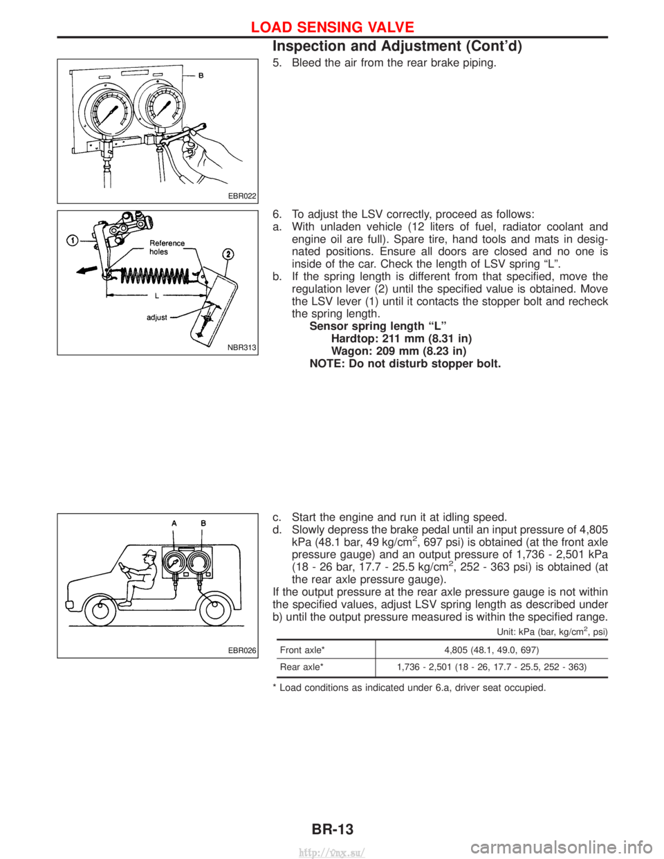
5. Bleed the air from the rear brake piping.
6. To adjust the LSV correctly, proceed as follows:
a. With unladen vehicle (12 liters of fuel, radiator coolant andengine oil are full). Spare tire, hand tools and mats in desig-
nated positions. Ensure all doors are closed and no one is
inside of the car. Check the length of LSV spring ªLº.
b. If the spring length is different from that specified, move the regulation lever (2) until the specified value is obtained. Move
the LSV lever (1) until it contacts the stopper bolt and recheck
the spring length.Sensor spring length ªLº Hardtop: 211 mm (8.31 in)
Wagon: 209 mm (8.23 in)
NOTE: Do not disturb stopper bolt.
c. Start the engine and run it at idling speed.
d. Slowly depress the brake pedal until an input pressure of 4,805 kPa (48.1 bar, 49 kg/cm
2, 697 psi) is obtained (at the front axle
pressure gauge) and an output pressure of 1,736 - 2,501 kPa
(18 - 26 bar, 17.7 - 25.5 kg/cm
2, 252 - 363 psi) is obtained (at
the rear axle pressure gauge).
If the output pressure at the rear axle pressure gauge is not within
the specified values, adjust LSV spring length as described under
b) until the output pressure measured is within the specified range.
Unit: kPa (bar, kg/cm2, psi)
Front axle* 4,805 (48.1, 49.0, 697)
Rear axle* 1,736 - 2,501 (18 - 26, 17.7 - 25.5, 252 - 363)
* Load conditions as indicated under 6.a, driver seat occupied.
EBR022
NBR313
EBR026
LOAD SENSING VALVE
Inspection and Adjustment (Cont'd)
BR-13
http://vnx.su/
Page 1256 of 1833
Special Service Tools
*: Special tool or commercial equivalent
Tool number
Tool nameDescription
KV48100700
Torque adapter
Measuring pinion rotating torque
ST27180001*
Steering wheel puller
Removing and installing steering wheel
ST27850000
Ball joint remover
Removing ball joint
ST29020001*
Steering gear arm puller
Removing and installing pitman arm
ST3127S000*
q
1GG91030000
Torque wrench
q
2HT62940000
Socket adapter
q
3HT62900000
Socket adapter
Measuring turning torque
KV48100301*
Strut & steering gearbox
attachment
Steering gear is installed
KV48103500-A
Pressure gauge
Measuring oil pressure
KV48102500
Pressure gauge adapter
Measuring oil pressure
KV481009S0
Oil seal drift set
q
1KV48100910
Drift
q
2KV48100920
Adapter
q
3KV48100930
Adapter
Installing oil seal
PREPARATION
ST-3
http://vnx.su/
Page 1259 of 1833
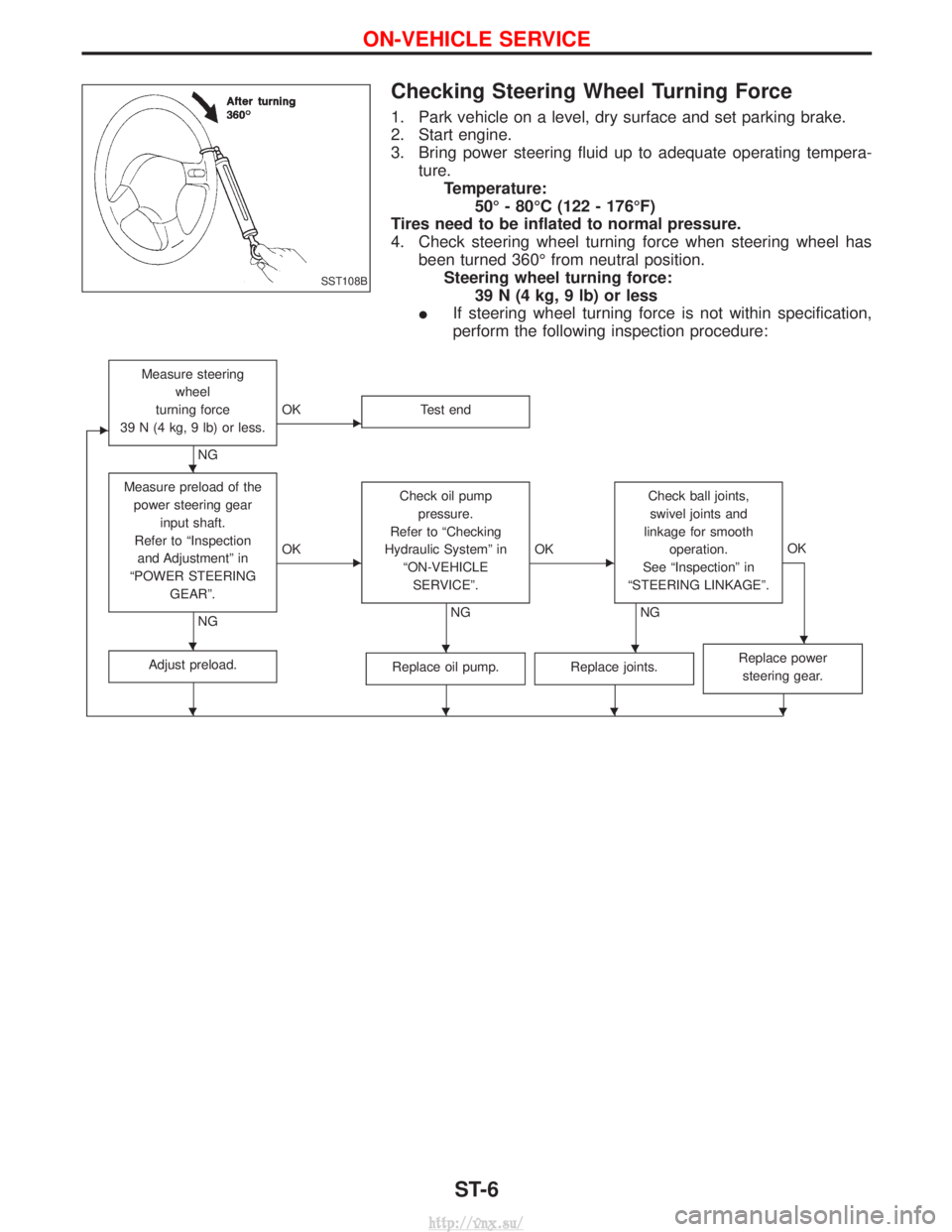
Checking Steering Wheel Turning Force
1. Park vehicle on a level, dry surface and set parking brake.
2. Start engine.
3. Bring power steering fluid up to adequate operating tempera-ture.Temperature: 50É - 80ÉC (122 - 176ÉF)
Tires need to be inflated to normal pressure.
4. Check steering wheel turning force when steering wheel has been turned 360É from neutral position.Steering wheel turning force: 39 N (4 kg, 9 lb) or less
I If steering wheel turning force is not within specification,
perform the following inspection procedure:
E
Measure steering
wheel
turning force
39 N (4 kg, 9 lb) or less.
NG
EOK Test end
Measure preload of the
power steering gear input shaft.
Refer to ªInspection and Adjustmentº in
ªPOWER STEERING GEARº.
NG
EOK Check oil pump
pressure.
Refer to ªChecking
Hydraulic Systemº in ªON-VEHICLESERVICEº.
NG
EOK Check ball joints,
swivel joints and
linkage for smooth operation.
See ªInspectionº in
ªSTEERING LINKAGEº.
NG OK
Adjust preload.Replace oil pump.Replace joints.Replace power
steering gear.
SST108B
H
HHHH
HHHH
ON-VEHICLE SERVICE
ST-6
http://vnx.su/
Page 1260 of 1833
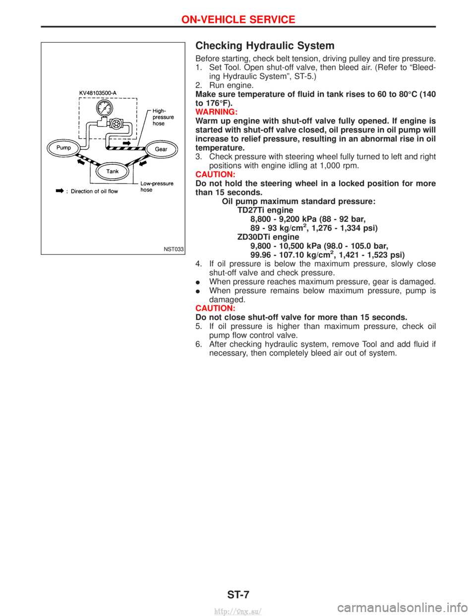
Checking Hydraulic System
Before starting, check belt tension, driving pulley and tire pressure.
1. Set Tool. Open shut-off valve, then bleed air. (Refer to ªBleed-ing Hydraulic Systemº, ST-5.)
2. Run engine.
Make sure temperature of fluid in tank rises to 60 to 80ÉC (140
to 176ÉF).
WARNING:
Warm up engine with shut-off valve fully opened. If engine is
started with shut-off valve closed, oil pressure in oil pump will
increase to relief pressure, resulting in an abnormal rise in oil
temperature.
3. Check pressure with steering wheel fully turned to left and right positions with engine idling at 1,000 rpm.
CAUTION:
Do not hold the steering wheel in a locked position for more
than 15 seconds. Oil pump maximum standard pressure:TD27Ti engine8,800 - 9,200 kPa (88 - 92 bar,
89 - 93 kg/cm
2, 1,276 - 1,334 psi)
ZD30DTi engine 9,800 - 10,500 kPa (98.0 - 105.0 bar,
99.96 - 107.10 kg/cm
2, 1,421 - 1,523 psi)
4. If oil pressure is below the maximum pressure, slowly close shut-off valve and check pressure.
I When pressure reaches maximum pressure, gear is damaged.
I When pressure remains below maximum pressure, pump is
damaged.
CAUTION:
Do not close shut-off valve for more than 15 seconds.
5. If oil pressure is higher than maximum pressure, check oil pump flow control valve.
6. After checking hydraulic system, remove Tool and add fluid if necessary, then completely bleed air out of system.NST033
ON-VEHICLE SERVICE
ST-7
http://vnx.su/
Page 1275 of 1833
General Specifications
ModelsAll
Steering gear type ZF 8054
Turns of steering
wheel
(Lock to lock) 3.86
Overall gear ratio 17.1 : 1
Steering column type Collapsible, adjustable height
Inspection and Adjustment
STEERING WHEEL AND COLUMN
Applied model AIR BAG
Steering wheel axial play mm (in) 0 (0)
Steering wheel play mm (in) 35 (1.38) or less
Steering column length ªLº mm (in) 830.5 - 832.7
(32.697 - 32.783)
EST018
STEERING GEAR AND LINKAGE
Ball joint and swivel joint
Rotating torque ªBº N×m (kg-m, in-lb) 0.5 - 5.0
(0.05 - 0.51, 4 - 44)
Axial end play ªCº mm (in) 0 - 0.2 (0 - 0.008)
Radial play ªDº mm (in) 0 (0)
Length ªLº mm (in) 287 (11.30)
SST583B
OIL PUMP
Unit: kPa (bar, kg/cm2, psi)
EngineZD30DDTiTD27Ti
Make UNISIA
Max. pressure 9,800 - 10,500
(98.0 - 105.0,
99.96 - 107.10, 1,421 - 1,523) 8,800 - 9,200
(88 - 92,89 - 93,
1,276 - 1,334)
SERVICE DATA AND SPECIFICATIONS (SDS)
ST-22
http://vnx.su/
Page 1402 of 1833
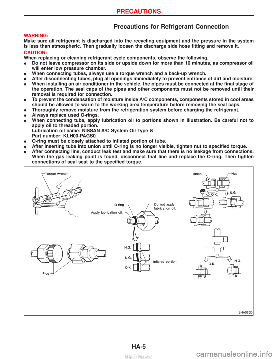
Precautions for Refrigerant Connection
WARNING:
Make sure all refrigerant is discharged into the recycling equipment and the pressure in the system
is less than atmospheric. Then gradually loosen the discharge side hose fitting and remove it.
CAUTION:
When replacing or cleaning refrigerant cycle components, observe the following.
IDo not leave compressor on its side or upside down for more than 10 minutes, as compressor oil
will enter low pressure chamber.
I When connecting tubes, always use a torque wrench and a back-up wrench.
I After disconnecting tubes, plug all openings immediately to prevent entrance of dirt and moisture.
I When installing an air conditioner in the vehicle, the pipes must be connected at the final stage of
the operation. The seal caps of the pipes and other components must not be removed until their
removal is required for connection.
I To prevent the condensation of moisture inside A/C components, components stored in cool areas
should be allowed to warm to the working area temperature before removing the seal caps.
I Thoroughly remove moisture from the refrigeration system before charging the refrigerant.
I Always replace used O-rings.
I When connecting tube, apply lubrication oil to portions shown in illustration. Be careful not to
apply oil to threaded portion.
Lubrication oil name: NISSAN A/C System Oil Type S
Part number: KLH00-PAGS0
I O-ring must be closely attached to inflated portion of tube.
I After inserting tube into union until O-ring is no longer visible, tighten nut to specified torque.
I After connecting line, conduct leak test and make sure that there is no leakage from connections.
When the gas leaking point is found, disconnect that line and replace the O-ring. Then tighten
connections of seal seat to the specified torque.
SHA525D
PRECAUTIONS
HA-5
http://vnx.su/
Page 1403 of 1833
Precautions for Servicing Compressor
IAttach a blind plug to the suction port (low pressure) and discharge port (high pressure) of the
compressor to prevent oil from leaking out and dust from getting inside.
I When the compressor is removed, store it under the same condition as it is when mounted on the
car.
I When replacing or repairing compressor, be sure to remove oil from the compressor and check
the oil quantity extracted.
I When replacing with a new compressor, be sure to remove oil from the new compressor so that
the quantity of oil remaining in the new compressor is equal to the quantity collected from the
removed compressor. See the section ªLUBRICATION OILº.
I Pay attention so as not to allow dirt and oil to attach on the friction surfaces between clutch and
pulley. If the surface is contaminated, with oil, wipe it off by using a clean waste cloth moistened
with thinner.
I After completing the compressor service operation, be sure to rotate the compressor shaft more
than five turns in both directions by hand to equalize oil distribution inside the compressor, then
run the compressor for about one hour by idling the engine.
I When the compressor magnet clutch has been replaced, be sure to check the magnet clutch for
normal operation by applying voltage to the clutch.
PRECAUTIONS
HA-6
http://vnx.su/
Page 1407 of 1833
Refrigeration Cycle
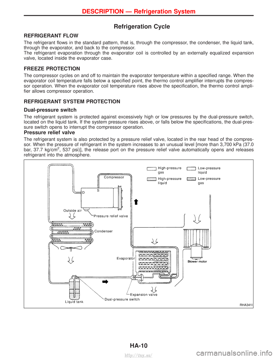
REFRIGERANT FLOW
The refrigerant flows in the standard pattern, that is, through the compressor, the condenser, the liquid tank,
through the evaporator, and back to the compressor.
The refrigerant evaporation through the evaporator coil is controlled by an externally equalized expansion
valve, located inside the evaporator case.
FREEZE PROTECTION
The compressor cycles on and off to maintain the evaporator temperature within a specified range. When the
evaporator coil temperature falls below a specified point, the thermo control amplifier interrupts the compres-
sor operation. When the evaporator coil temperature rises above the specification, the thermo control ampli-
fier allows compressor operation.
REFRIGERANT SYSTEM PROTECTION
Dual-pressure switch
The refrigerant system is protected against excessively high or low pressures by the dual-pressure switch,
located on the liquid tank. If the system pressure rises above, or falls below the specifications, the dual-pres-
sure switch opens to interrupt the compressor operation.
Pressure relief valve
The refrigerant system is also protected by a pressure relief valve, located in the rear head of the compres-
sor. When the pressure of refrigerant in the system increases to an unusual level [more than 3,700 kPa (37.0
bar, 37.7 kg/cm
2, 537 psi)], the release port on the pressure relief valve automatically opens and releases
refrigerant into the atmosphere.
RHA341I
DESCRIPTION Ð Refrigeration System
HA-10
http://vnx.su/