Page 332 of 1833
SYSTEM Ð Basic engine control sys-
temSYMPTOM
Reference page
Feature of symptom, Check pointROUGH IDLE/HUNTING
IDLING VIBRATION
SLOW/NO RETURN TO IDLE
OVERHEAT/HIGH ENGINE COOLANT TEMPERATURE
EXCESSIVE FUEL CONSUMPTION
EXCESSIVE OIL CONSUMPTION
ABNORMAL SMOKE COLOR
DEAD BATTERY (UNDER CHARGE)
Malfunction indicator lamp illuminates.
Can be detected by CONSULT-II?
Fuel cut BLACK SMOKE
WHITE SMOKEWarranty symptom code
AG AH AJ AK AL AM AP HA
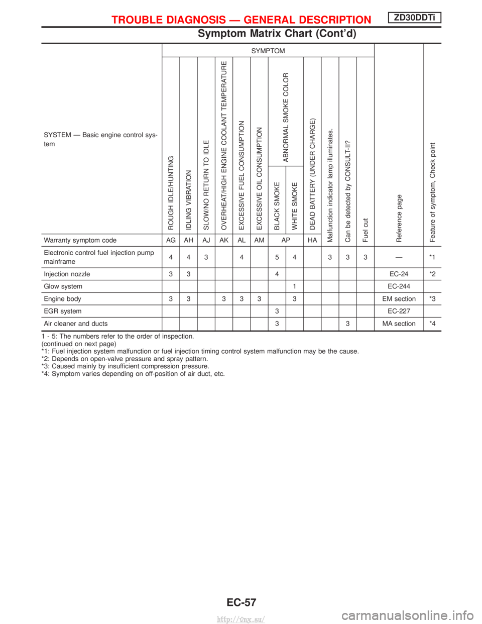
Electronic control fuel injection pump
mainframe 443 4 54 333 Ð *1
Injection nozzle 3 34 EC-24 *2
Glow system 1 EC-244
Engine body 3 3 3 3 3 3 EM section *3
EGR system 3 EC-227
Air cleaner and ducts 3 3 MA section *4
1 - 5: The numbers refer to the order of inspection.
(continued on next page)
*1: Fuel injection system malfunction or fuel injection timing control system malfunction may be the cause.
*2: Depends on open-valve pressure and spray pattern.
*3: Caused mainly by insufficient compression pressure.
*4: Symptom varies depending on off-position of air duct, etc.
TROUBLE DIAGNOSIS Ð GENERAL DESCRIPTIONZD30DDTi
Symptom Matrix Chart (Cont'd)
EC-57
http://vnx.su/
Page 336 of 1833
SYSTEM Ð ENGINE CONTROL system
Malfunction
SYMPTOM
Reference page
Feature of symptom, Check pointROUGH IDLE/HUNTING
IDLING VIBRATION
SLOW/NO RETURN TO IDLE
OVERHEAT/HIGH ENGINE COOLANT TEMPERATURE
EXCESSIVE FUEL CONSUMPTION
EXCESSIVE OIL CONSUMPTION
ABNORMAL SMOKE COLOR
DEAD BATTERY (UNDER CHARGE)
Malfunction indicator lamp illuminates.
Can be detected by CONSULT-II?
Fuel cut BLACK SMOKE
WHITE SMOKEWarranty symptom code
AG AH AJ AK AL AM AP HA
ENGINE CONTROL
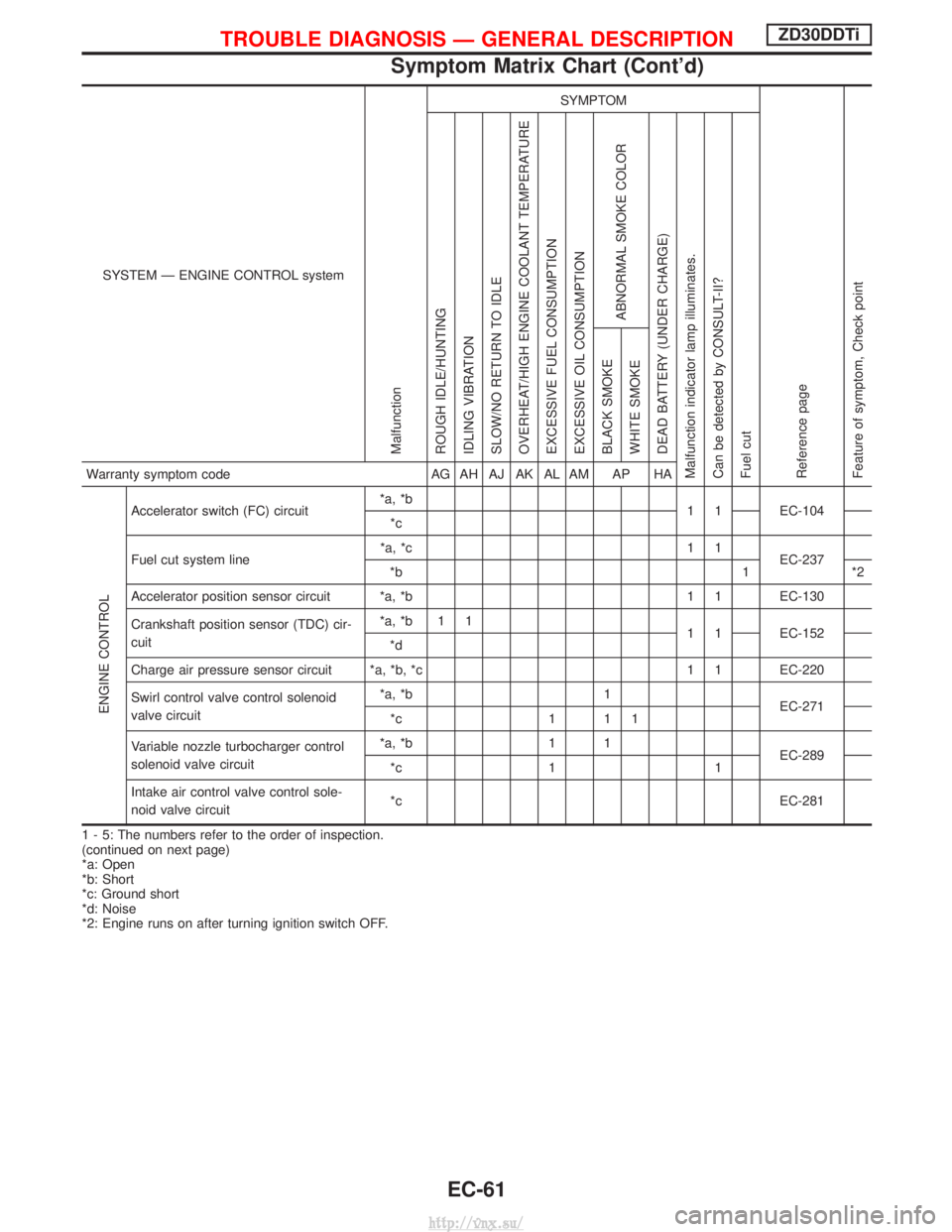
Accelerator switch (FC) circuit*a, *b
1 1 EC-104
*c
Fuel cut system line *a, *c 1 1
EC-237
*b 1 *2
Accelerator position sensor circuit *a, *b 1 1 EC-130
Crankshaft position sensor (TDC) cir-
cuit *a, *b 1 1
1 1 EC-152
*d
Charge air pressure sensor circuit *a, *b, *c 1 1 EC-220
Swirl control valve control solenoid
valve circuit *a, *b 1
EC-271
*c 1 1 1
Variable nozzle turbocharger control
solenoid valve circuit *a, *b 1 1
EC-289
*c 1 1
Intake air control valve control sole-
noid valve circuit *c EC-281
1 - 5: The numbers refer to the order of inspection.
(continued on next page)
*a: Open
*b: Short
*c: Ground short
*d: Noise
*2: Engine runs on after turning ignition switch OFF.
TROUBLE DIAGNOSIS Ð GENERAL DESCRIPTIONZD30DDTi
Symptom Matrix Chart (Cont'd)
EC-61
http://vnx.su/
Page 348 of 1833
TER-
MINAL NO. WIRE
COLOR ITEM CONDITION DATA (DC Voltage and Pulse
Signal)
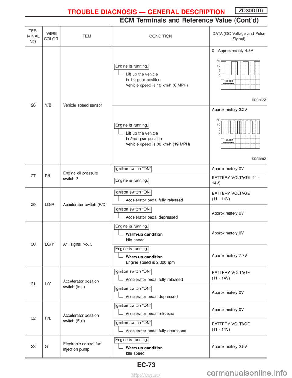
26 Y/B Vehicle speed sensor Engine is running.
Lift up the vehicle
In 1st gear position
Vehicle speed is 10 km/h (6 MPH)
0 - Approximately 4.8V
SEF257Z
Engine is running.
Lift up the vehicle
In 2nd gear position
Vehicle speed is 30 km/h (19 MPH)Approximately 2.2V
SEF258Z
27 R/L
Engine oil pressure
switch-2 Ignition switch ªONº
Approximately 0V
Engine is running.
BATTERY VOLTAGE (11 -
14V)
29 LG/R Accelerator switch (F/C) Ignition switch ªONº
Accelerator pedal fully released
BATTERY VOLTAGE
(11 - 14V)
Ignition switch ªONº
Accelerator pedal depressed Approximately 0V
30 LG/Y A/T signal No. 3 Engine is running.
Warm-up condition
Idle speed
Approximately 0V
Engine is running.
Warm-up condition
Engine speed is 2,000 rpm Approximately 7.7V
31 L/Y Accelerator position
switch (Idle) Ignition switch ªONº
Accelerator pedal fully released
BATTERY VOLTAGE
(11 - 14V)
Ignition switch ªONº
Accelerator pedal depressed Approximately 0V
32 R/L Accelerator position
switch (Full) Ignition switch ªONº
Accelerator pedal released
Approximately 0V
Ignition switch ªONº
Accelerator pedal fully depressed BATTERY VOLTAGE
(11 - 14V)
33 G Electronic control fuel
injection pump Engine is running.
Warm-up condition
Idle speed
Approximately 2.5V
TROUBLE DIAGNOSIS Ð GENERAL DESCRIPTIONZD30DDTi
ECM Terminals and Reference Value (Cont'd)
EC-73
http://vnx.su/
Page 572 of 1833
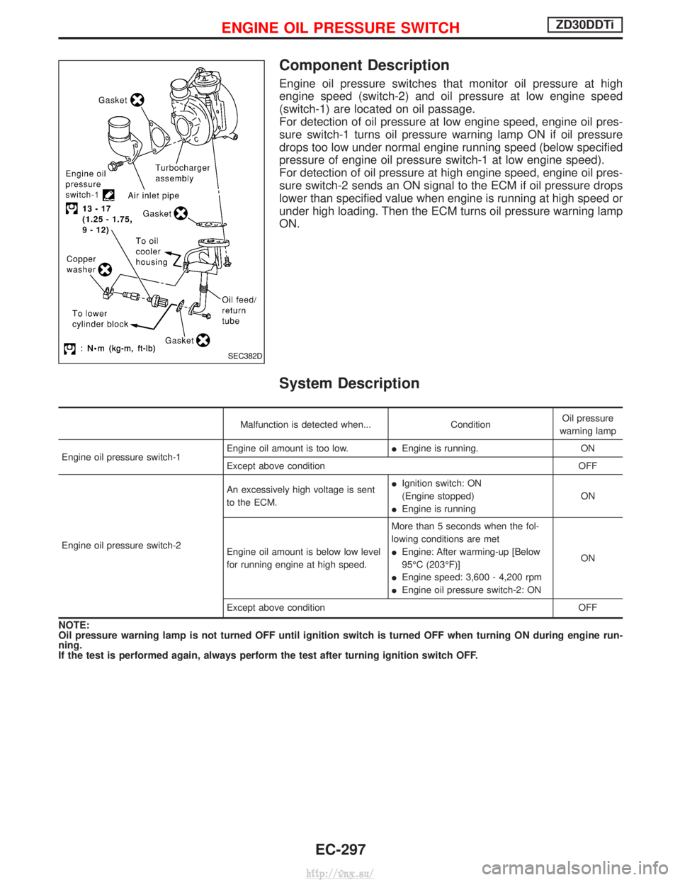
Component Description
Engine oil pressure switches that monitor oil pressure at high
engine speed (switch-2) and oil pressure at low engine speed
(switch-1) are located on oil passage.
For detection of oil pressure at low engine speed, engine oil pres-
sure switch-1 turns oil pressure warning lamp ON if oil pressure
drops too low under normal engine running speed (below specified
pressure of engine oil pressure switch-1 at low engine speed).
For detection of oil pressure at high engine speed, engine oil pres-
sure switch-2 sends an ON signal to the ECM if oil pressure drops
lower than specified value when engine is running at high speed or
under high loading. Then the ECM turns oil pressure warning lamp
ON.
System Description
Malfunction is detected when...ConditionOil pressure
warning lamp
Engine oil pressure switch-1 Engine oil amount is too low.
IEngine is running. ON
Except above condition OFF
Engine oil pressure switch-2 An excessively high voltage is sent
to the ECM.
I
Ignition switch: ON
(Engine stopped)
I Engine is running ON
Engine oil amount is below low level
for running engine at high speed. More than 5 seconds when the fol-
lowing conditions are met
I
Engine: After warming-up [Below
95ÉC (203ÉF)]
I Engine speed: 3,600 - 4,200 rpm
I Engine oil pressure switch-2: ON ON
Except above condition OFF
NOTE:
Oil pressure warning lamp is not turned OFF until ignition switch is turned OFF when turning ON during engine run-
ning.
If the test is performed again, always perform the test after turning ignition switch OFF.
SEC382D
ENGINE OIL PRESSURE SWITCHZD30DDTi
EC-297
http://vnx.su/
Page 573 of 1833
ECM Terminals and Reference Value
Specification data are reference values and are measured between each terminal and ground.
CAUTION:
Do not use ECM ground terminals when measuring input/output voltage. Doing so may result in dam-
age to the ECM's transistor. Use a ground other than ECM terminals, such as the ground.
TERMINALNO. WIRE
COLOR ITEM CONDITION DATA (DC Voltage)
6 Y Oil pressure warning lamp [Ignition switch ªONº]
I
Oil pressure warning lamp is
illuminated Approximately 0V
[Engine is running]
I Oil pressure warning lamp is
not illuminated Battery voltage (12 - 14V)
27 R/L Engine oil pressure switch-2 [Ignition switch ªONº] Approximately 0V
[Engine is running]
I
Engine speed is 3,600 rpm Battery voltage (12 - 14V)
ENGINE OIL PRESSURE SWITCHZD30DDTi
EC-298
http://vnx.su/
Page 574 of 1833
Wiring Diagram
LHD MODELS
YEC667A
ENGINE OIL PRESSURE SWITCHZD30DDTi
EC-299
http://vnx.su/
Page 575 of 1833
RHD MODELS
YEC668A
ENGINE OIL PRESSURE SWITCHZD30DDTi
Wiring Diagram (Cont'd)EC-300
http://vnx.su/
Page 576 of 1833
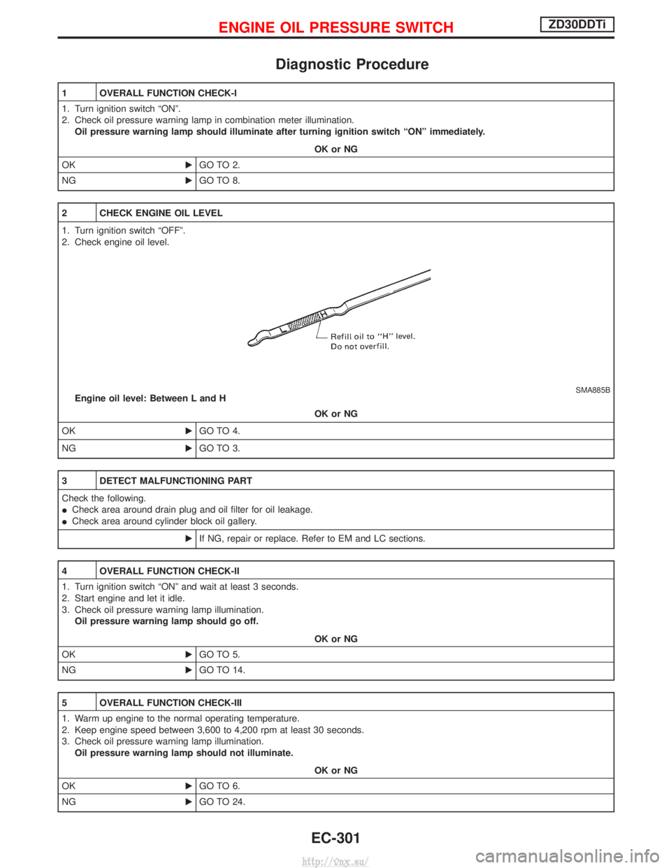
Diagnostic Procedure
1 OVERALL FUNCTION CHECK-I
1. Turn ignition switch ªONº.
2. Check oil pressure warning lamp in combination meter illumination.Oil pressure warning lamp should illuminate after turning ignition switch ªONº immediately.
OK or NG
OK EGO TO 2.
NG EGO TO 8.
2 CHECK ENGINE OIL LEVEL
1. Turn ignition switch ªOFFº.
2. Check engine oil level.
SMA885BEngine oil level: Between L and H
OK or NG
OK EGO TO 4.
NG EGO TO 3.
3 DETECT MALFUNCTIONING PART
Check the following.
ICheck area around drain plug and oil filter for oil leakage.
I Check area around cylinder block oil gallery.
EIf NG, repair or replace. Refer to EM and LC sections.
4 OVERALL FUNCTION CHECK-II
1. Turn ignition switch ªONº and wait at least 3 seconds.
2. Start engine and let it idle.
3. Check oil pressure warning lamp illumination.
Oil pressure warning lamp should go off.
OK or NG
OK EGO TO 5.
NG EGO TO 14.
5 OVERALL FUNCTION CHECK-III
1. Warm up engine to the normal operating temperature.
2. Keep engine speed between 3,600 to 4,200 rpm at least 30 seconds.
3. Check oil pressure warning lamp illumination.
Oil pressure warning lamp should not illuminate.
OK or NG
OK EGO TO 6.
NG EGO TO 24.
ENGINE OIL PRESSURE SWITCHZD30DDTi
EC-301
http://vnx.su/