2004 NISSAN TERRANO oil pressure
[x] Cancel search: oil pressurePage 96 of 1833
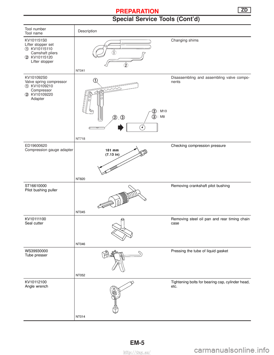
Tool number
Tool nameDescription
KV101151S0
Lifter stopper set
q
1KV10115110
Camshaft pliers
q
2KV10115120
Lifter stopper
NT041
Changing shims
KV101092S0
Valve spring compressor
q
1KV10109210
Compressor
q
2KV10109220
Adapter
NT718
Disassembling and assembling valve compo-
nents
ED19600620
Compression gauge adapter
NT820
Checking compression pressure
ST16610000
Pilot bushing puller
NT045
Removing crankshaft pilot bushing
KV101111 0 0
Seal cutter
NT046
Removing steel oil pan and rear timing chain
case
WS39930000
Tube presser
NT052
Pressing the tube of liquid gasket
KV10112100
Angle wrench
NT014
Tightening bolts for bearing cap, cylinder head,
etc.
PREPARATIONZD
Special Service Tools (Cont'd)
EM-5
http://vnx.su/
Page 101 of 1833
1. Warm up engine.
2. Turn ignition switch OFF.
3. Using CONSULT-II, make sure no error codes are indicated forself-diagnosis items. Refer to EC section, ªFuel Pressure
Releaseº.
I Do not disconnect CONSULT-II until the end of this operation;
it will be used to check engine rpm and for error detection at
the end of this operation.
4. Disconnect the negative battery terminal.
5. Remove the following parts.
I Intercooler
I Throttle body
I Rocker cover
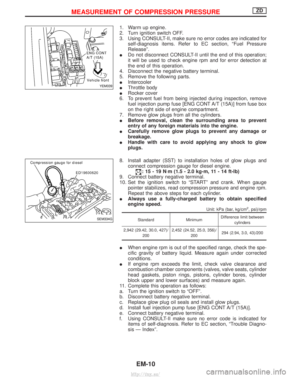
6. To prevent fuel from being injected during inspection, remove fuel injection pump fuse [ENG CONT A/T (15A)] from fuse box
on the right side of engine compartment.
7. Remove glow plugs from all the cylinders.
I Before removal, clean the surrounding area to prevent
entry of any foreign materials into the engine.
I Carefully remove glow plugs to prevent any damage or
breakage.
I Handle with care to avoid applying any shock to glow
plugs.
8. Install adapter (SST) to installation holes of glow plugs and connect compression gauge for diesel engine.
:15-19N ×m (1.5 - 2.0 kg-m, 11 - 14 ft-lb)
9. Connect battery negative terminal.
10. Set the ignition switch to ªSTARTº and crank. When gauge pointer stabilizes, read compression pressure and engine rpm.
Repeat the above steps for each cylinder.
I Always use a fully-charged battery to obtain specified
engine speed.
Unit: kPa (bar, kg/cm2, psi)/rpm
Standard MinimumDifference limit between
cylinders
2,942 (29.42, 30.0, 427)/ 200 2,452 (24.52, 25.0, 356)/
200 294 (2.94, 3.0, 43)/200
I
When engine rpm is out of the specified range, check the spe-
cific gravity of battery liquid. Measure again under corrected
conditions.
I If engine rpm exceeds the limit, check valve clearance and
combustion chamber components (valves, valve seats, cylinder
head gaskets, piston rings, pistons, cylinder bores, cylinder
block upper and lower surfaces) and measure again.
11. Complete this operation as follows:
a. Turn the ignition switch to ªOFFº.
b. Disconnect battery negative terminal.
c. Replace glow plug oil seals and install glow plugs.
d. Install fuel injection pump fuse [ENG CONT A/T (15A)].
e. Connect battery negative terminal.
f. Using CONSULT-II make sure no error code is indicated for items of self-diagnosis. Refer to EC section, ªTrouble Diagno-
sis Ð Indexº.
YEM039
SEM334G
MEASUREMENT OF COMPRESSION PRESSUREZD
EM-10
http://vnx.su/
Page 107 of 1833
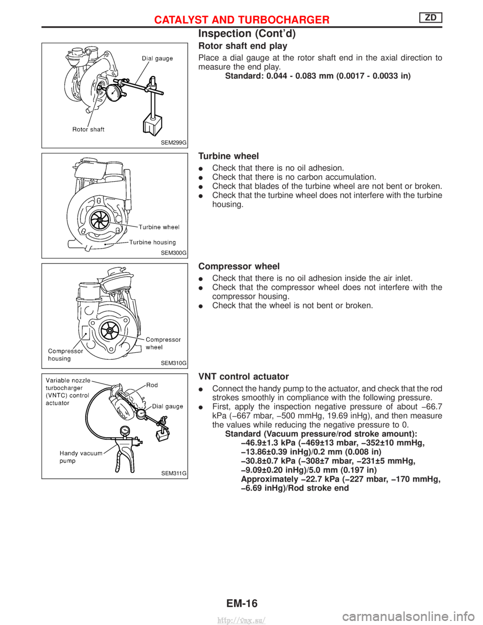
Rotor shaft end play
Place a dial gauge at the rotor shaft end in the axial direction to
measure the end play.Standard: 0.044 - 0.083 mm (0.0017 - 0.0033 in)
Turbine wheel
ICheck that there is no oil adhesion.
I Check that there is no carbon accumulation.
I Check that blades of the turbine wheel are not bent or broken.
I Check that the turbine wheel does not interfere with the turbine
housing.
Compressor wheel
ICheck that there is no oil adhesion inside the air inlet.
I Check that the compressor wheel does not interfere with the
compressor housing.
I Check that the wheel is not bent or broken.
VNT control actuator
IConnect the handy pump to the actuator, and check that the rod
strokes smoothly in compliance with the following pressure.
I First, apply the inspection negative pressure of about þ66.7
kPa (þ667 mbar, þ500 mmHg, 19.69 inHg), and then measure
the values while reducing the negative pressure to 0.
Standard (Vacuum pressure/rod stroke amount): þ46.9 1.3 kPa (þ469 13 mbar, þ352 10 mmHg,
þ13.86 0.39 inHg)/0.2 mm (0.008 in)
þ30.8 0.7 kPa (þ308 7 mbar, þ231 5 mmHg,
þ9.09 0.20 inHg)/5.0 mm (0.197 in)
Approximately þ22.7 kPa (þ227 mbar, þ170 mmHg,
þ6.69 inHg)/Rod stroke end
SEM299G
SEM300G
SEM310G
SEM311G
CATALYST AND TURBOCHARGERZD
Inspection (Cont'd)
EM-16
http://vnx.su/
Page 108 of 1833
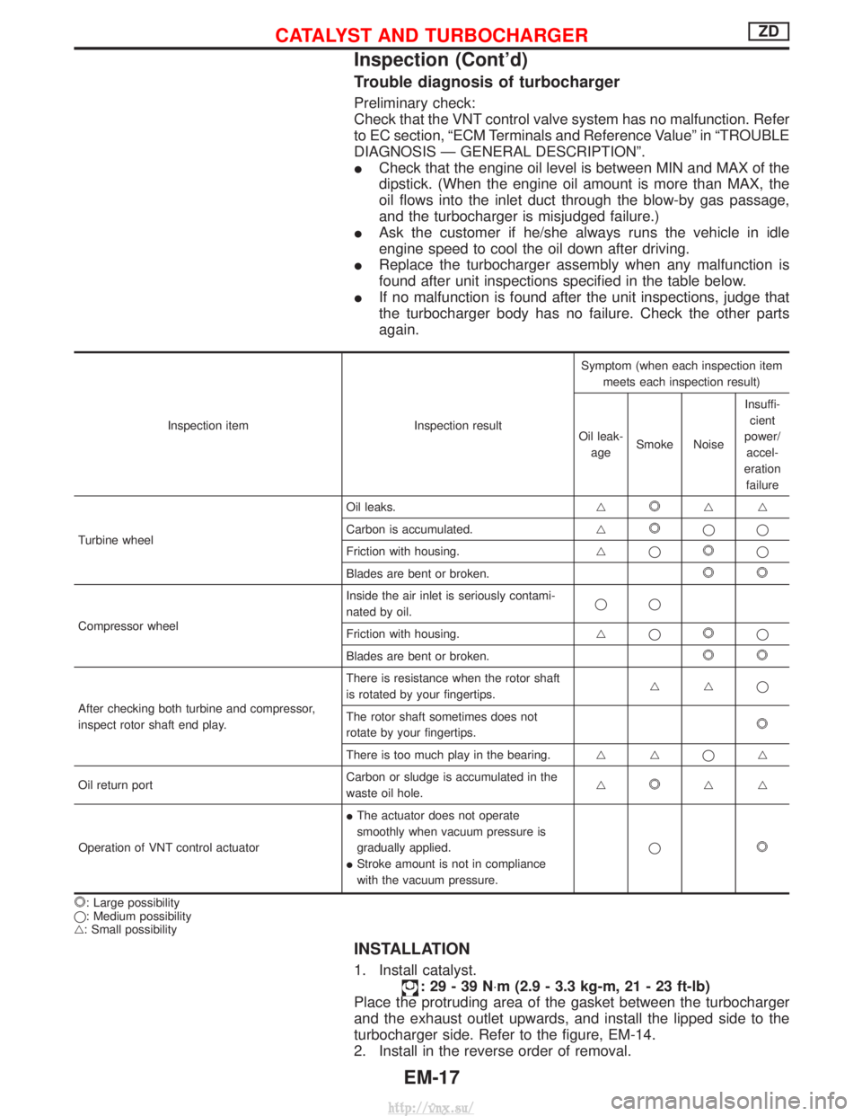
Trouble diagnosis of turbocharger
Preliminary check:
Check that the VNT control valve system has no malfunction. Refer
to EC section, ªECM Terminals and Reference Valueº in ªTROUBLE
DIAGNOSIS Ð GENERAL DESCRIPTIONº.
ICheck that the engine oil level is between MIN and MAX of the
dipstick. (When the engine oil amount is more than MAX, the
oil flows into the inlet duct through the blow-by gas passage,
and the turbocharger is misjudged failure.)
I Ask the customer if he/she always runs the vehicle in idle
engine speed to cool the oil down after driving.
I Replace the turbocharger assembly when any malfunction is
found after unit inspections specified in the table below.
I If no malfunction is found after the unit inspections, judge that
the turbocharger body has no failure. Check the other parts
again.
Inspection item Inspection resultSymptom (when each inspection item
meets each inspection result)
Oil leak- age Smoke Noise Insuffi-
cient
power/ accel-
eration failure
Turbine wheel Oil leaks.
g
gg
Carbon is accumulated. g
qq
Friction with housing. gq
q
Blades are bent or broken.
Compressor wheel Inside the air inlet is seriously contami-
nated by oil.
qq
Friction with housing. gqq
Blades are bent or broken.
After checking both turbine and compressor,
inspect rotor shaft end play. There is resistance when the rotor shaft
is rotated by your fingertips.
ggq
The rotor shaft sometimes does not
rotate by your fingertips.
There is too much play in the bearing. g gqg
Oil return port Carbon or sludge is accumulated in the
waste oil hole.g
gg
Operation of VNT control actuator I
The actuator does not operate
smoothly when vacuum pressure is
gradually applied.
I Stroke amount is not in compliance
with the vacuum pressure. q
: Large possibility
q: Medium possibility
g: Small possibility
INSTALLATION
1. Install catalyst.
:29-39N ×m (2.9 - 3.3 kg-m, 21 - 23 ft-lb)
Place the protruding area of the gasket between the turbocharger
and the exhaust outlet upwards, and install the lipped side to the
turbocharger side. Refer to the figure, EM-14.
2. Install in the reverse order of removal.
CATALYST AND TURBOCHARGERZD
Inspection (Cont'd)
EM-17
http://vnx.su/
Page 130 of 1833
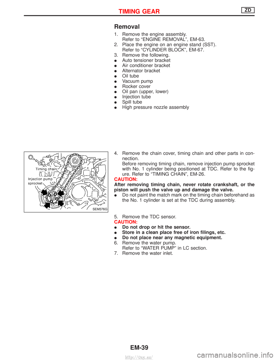
Removal
1. Remove the engine assembly.Refer to ªENGINE REMOVALº, EM-63.
2. Place the engine on an engine stand (SST). Refer to ªCYLINDER BLOCKº, EM-67.
3. Remove the following.
I Auto tensioner bracket
I Air conditioner bracket
I Alternator bracket
I Oil tube
I Vacuum pump
I Rocker cover
I Oil pan (upper, lower)
I Injection tube
I Spill tube
I High pressure nozzle assembly
4. Remove the chain cover, timing chain and other parts in con- nection.
Before removing timing chain, remove injection pump sprocket
with No. 1 cylinder being positioned at TDC. Refer to the fig-
ure. Refer to ªTIMING CHAINº, EM-26.
CAUTION:
After removing timing chain, never rotate crankshaft, or the
piston will push the valve up and damage the valve.
I Do not paint the match mark on the timing chain beforehand as
the No. 1 cylinder is set at the TDC during assembly.
5. Remove the TDC sensor.
CAUTION:
I Do not drop or hit the sensor.
I Store in a clean place free of iron filings, etc.
I Do not place near any magnetic equipment.
6. Remove the water pump. Refer to ªWATER PUMPº in LC section.
7. Remove the water inlet.
SEM376G
TIMING GEARZD
EM-39
http://vnx.su/
Page 143 of 1833
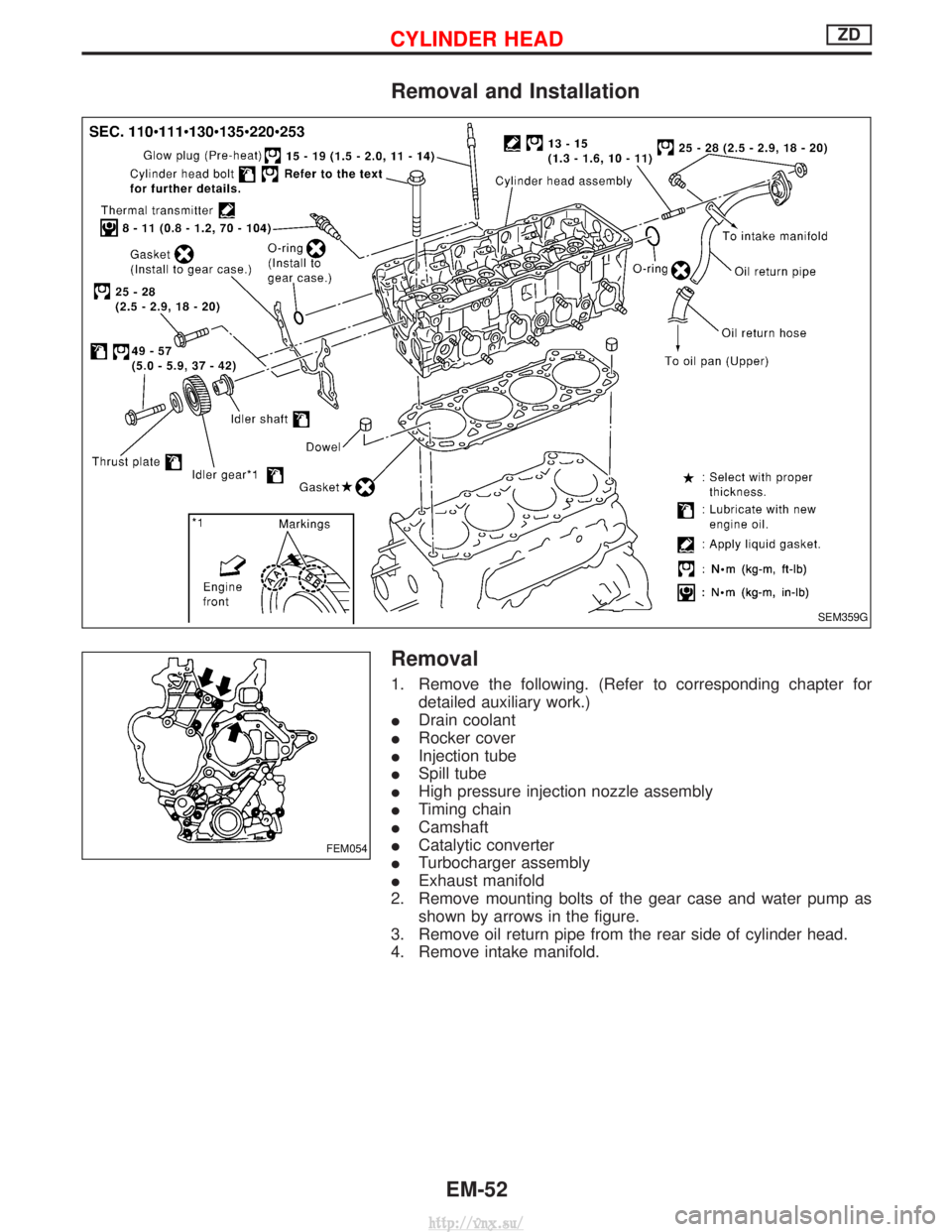
Removal and Installation
Removal
1. Remove the following. (Refer to corresponding chapter fordetailed auxiliary work.)
I Drain coolant
I Rocker cover
I Injection tube
I Spill tube
I High pressure injection nozzle assembly
I Timing chain
I Camshaft
I Catalytic converter
I Turbocharger assembly
I Exhaust manifold
2. Remove mounting bolts of the gear case and water pump as shown by arrows in the figure.
3. Remove oil return pipe from the rear side of cylinder head.
4. Remove intake manifold.
SEM359G
FEM054
CYLINDER HEADZD
EM-52
http://vnx.su/
Page 155 of 1833

Engine room (Left)
3. Remove air duct and air cleaner case.
4. Disconnect vacuum hose to the vehicle on the engine.
5. Disconnect harness connectors from alternator and air com-pressor.
6. Remove alternator.
7. After removing refrigerant, remove pipes of air compressor and inlet/outlet.
8. Disconnect heating hose, install blank cap to hose to prevent coolant from leaking.
9. Remove heating pipe.
10. Remove heat insulator.
11. Remove catalytic converter.
Engine room (Right)
12. Remove power steering reservoir tank from bracket, and fix it to the vehicle with a rope.
CAUTION:
Keep the reservoir tank level when fixing to prevent oil leak.
13. Remove fuel feed and return hoses.
CAUTION:
Install blank caps immediately to avoid fuel leakage.
14. Remove all harness connectors on the engine, and move har- nesses to the side of the vehicle.
Vehicle underfloor
15. Remove starter motor.
16. Detach A/T oil cooler pipes from oil pan. (A/T model)
17. Remove rear propeller shaft.
18. Remove mounting bolts to secure the engine to transmission.
1) Remove torque converter installation bolt. (A/T model)
2) Lift transmission bottom with transmission jack, and removerear mount members from the vehicle.
3) Lower transmission with the jack, and remove upper mounting bolts securing the engine to transmission.
4) Lift transmission with the jack, and reinstall rear mount mem- bers to the vehicle.
5) Position the jack to the front side of transmission.
6) Remove remaining mounting bolts securing the engine to trans- mission.
Removal operation
19. Remove air conditioner high pressure pipes at the rear of theengine room.
I This is due to some inconvenience in the rear slinger installa-
tion.
20. Install the engine slingers (standard service part) to front-left and rear-right.
:25-28N ×m (2.5 - 2.9 kg-m, 18 - 20 ft-lb)
WARNING:
For engines without engine slingers, attach proper slingers
and bolts described in the PARTS CATALOG.
FEM082
ENGINE REMOVALZD
Removal (Cont'd)
EM-64
http://vnx.su/
Page 159 of 1833
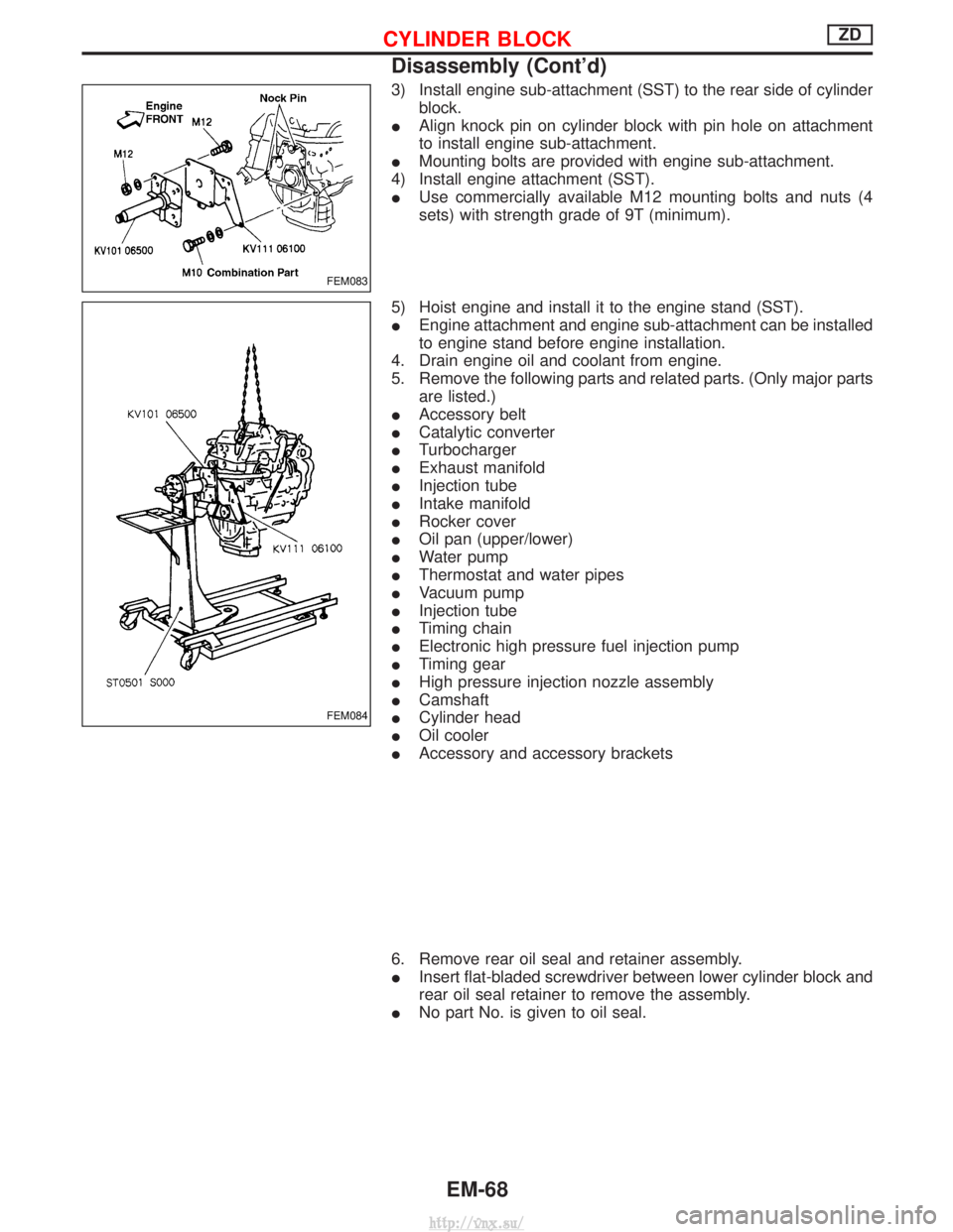
3) Install engine sub-attachment (SST) to the rear side of cylinderblock.
I Align knock pin on cylinder block with pin hole on attachment
to install engine sub-attachment.
I Mounting bolts are provided with engine sub-attachment.
4) Install engine attachment (SST).
I Use commercially available M12 mounting bolts and nuts (4
sets) with strength grade of 9T (minimum).
5) Hoist engine and install it to the engine stand (SST).
I Engine attachment and engine sub-attachment can be installed
to engine stand before engine installation.
4. Drain engine oil and coolant from engine.
5. Remove the following parts and related parts. (Only major parts are listed.)
I Accessory belt
I Catalytic converter
I Turbocharger
I Exhaust manifold
I Injection tube
I Intake manifold
I Rocker cover
I Oil pan (upper/lower)
I Water pump
I Thermostat and water pipes
I Vacuum pump
I Injection tube
I Timing chain
I Electronic high pressure fuel injection pump
I Timing gear
I High pressure injection nozzle assembly
I Camshaft
I Cylinder head
I Oil cooler
I Accessory and accessory brackets
6. Remove rear oil seal and retainer assembly.
I Insert flat-bladed screwdriver between lower cylinder block and
rear oil seal retainer to remove the assembly.
I No part No. is given to oil seal.
FEM083
FEM084
CYLINDER BLOCKZD
Disassembly (Cont'd)
EM-68
http://vnx.su/