Page 175 of 1833
General Specifications
Cylinder arrangementIn-line 4
Displacement cm
3(cu in)2,953 (180.19)
Bore and stroke mm (in) 96 x 102 (3.78 x 4.02)
Valve arrangement DOHC
Firing order 1-3-4-2
Number of piston rings Compression 2
Oil
1
Number of main bearings 5
Compression ratio 17.9
Compression Pressure
Unit: kPa (bar, kg/cm2, psi)/200 rpm
Compression pressureStandard 2,942 (29.42, 30.0, 427)
Minimum 2,452 (24.52, 25.0, 356)
Differential limit between cylinders 294 (2.94, 3.0, 43)
Cylinder Head
Unit: mm (in)
Standard
Limit
Head surface distortion Less than 0.05 (0.0020) 0.2 (0.008)
SEM368G
Valve
VA LV E
Unit: mm (in)
FEM067
SERVICE DATA AND SPECIFICATIONS (SDS)ZD
EM-84
http://vnx.su/
Page 194 of 1833

Measurement of Compression Pressure
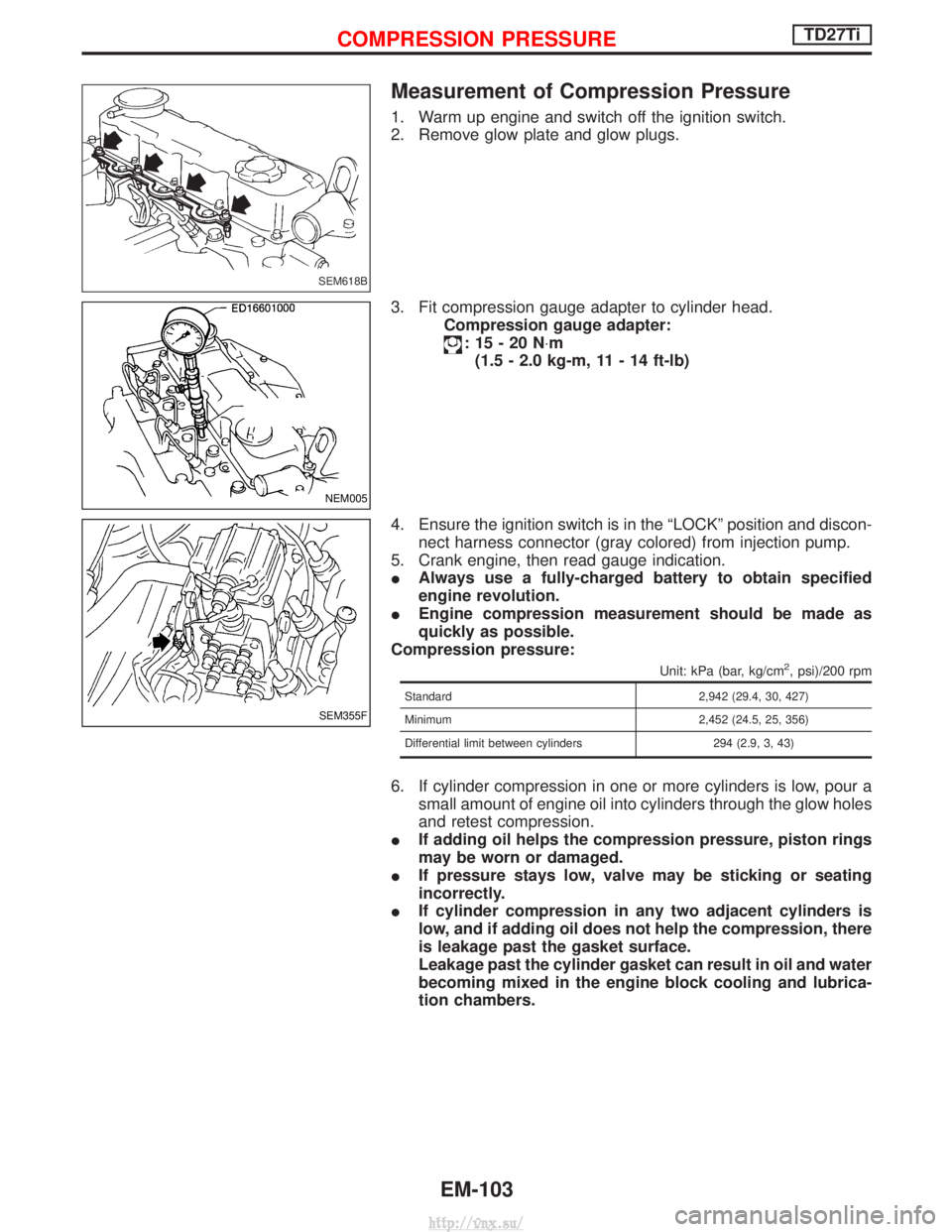
1. Warm up engine and switch off the ignition switch.
2. Remove glow plate and glow plugs.
3. Fit compression gauge adapter to cylinder head.Compression gauge adapter:
:15-20N ×m
(1.5 - 2.0 kg-m, 11 - 14 ft-lb)
4. Ensure the ignition switch is in the ªLOCKº position and discon- nect harness connector (gray colored) from injection pump.
5. Crank engine, then read gauge indication.
I Always use a fully-charged battery to obtain specified
engine revolution.
I Engine compression measurement should be made as
quickly as possible.
Compression pressure:
Unit: kPa (bar, kg/cm2, psi)/200 rpm
Standard 2,942 (29.4, 30, 427)
Minimum 2,452 (24.5, 25, 356)
Differential limit between cylinders 294 (2.9, 3, 43)
6. If cylinder compression in one or more cylinders is low, pour a small amount of engine oil into cylinders through the glow holes
and retest compression.
I If adding oil helps the compression pressure, piston rings
may be worn or damaged.
I If pressure stays low, valve may be sticking or seating
incorrectly.
I If cylinder compression in any two adjacent cylinders is
low, and if adding oil does not help the compression, there
is leakage past the gasket surface.
Leakage past the cylinder gasket can result in oil and water
becoming mixed in the engine block cooling and lubrica-
tion chambers.
SEM618B
NEM005
SEM355F
COMPRESSION PRESSURETD27Ti
EM-103
http://vnx.su/
Page 213 of 1833
TURBINE WHEEL
Check turbine wheel for the following.
IOil
I Carbon deposits
I Deformed fins
I Contact with turbine housing
COMPRESSOR WHEEL
Check compressor wheel for the following.
IOil
I Deformed fins
I Contact with compressor housing
WASTEGATE VALVE
Remove rod pin and check wastegate valve for cracks, deformation
and smooth movement. Check valve seat surface for smoothness.
Check operation of by-pass valve controller.
IMove by-pass valve to make sure that it is not sticking or
scratched.
I Measure rod end play of the by-pass valve controller.
Do not apply more than 102.6 kPa (1,026 mbar, 770 mmHg,
30.31 inHg) pressure to controller diaphragm. By-pass valve controller stroke/pressure:0.38 mm (0.015 in)/92 kPa (920 mbar, 690 mmHg,
27.17 inHg)
SEM828D
SEM829D
SEM830D
SEC727B
TURBOCHARGERTD27Ti
Inspection (Cont'd)
EM-122
http://vnx.su/
Page 234 of 1833
General Specifications
Engine modelTD27Ti
Cylinder arrangement 4, in-line
Displacement cm
3(cu in) 2,663 (162.5)
Bore x stroke mm (in) 96 x 92 (3.8 x 3.6)
Valve arrangement OHV
Firing order 1-3-4-2
Number of piston rings Compression 2
Oil 1
Number of main bearings 5
Compression ratio 21.9 0.2
Unit: kPa (bar, kg/cm
2, psi)/rpm
Compression pressureStandard 2,942 (29.4, 30, 427)/200
Minimum 2,452 (24.5, 25, 356)/200
Differential limit between
cylinders 294 (2.9, 3, 43)/200
SERVICE DATA AND SPECIFICATIONS (SDS)TD27Ti
EM-143
http://vnx.su/
Page 242 of 1833

ENGINE LUBRICATION &COOLING SYSTEMS
SECTION
LC
CONTENTS
ZD
PRECAUTIONS AND PREPARATION ............................2
Liquid Gasket Application Procedure ..........................2
Special Service Tools ..................................................2
ENGINE LUBRICATION SYSTEM ..................................3
Lubricating Circuit ........................................................3
Oil Pressure Check......................................................4
Oil Pump ......................................................................5
Oil Jet........................................................................\
...7
Oil Cooler .....................................................................8
ENGINE COOLING SYSTEM ..........................................9
Cooling Circuit .............................................................9
System Check............................................................10
Water Pump ............................................................... 11
Thermostat .................................................................12
Water Outlet ...............................................................13
Radiator .....................................................................14
Cooling Fan (Crankshaft driven) ...............................15
EGR Cooler ...............................................................16
SERVICE DATA AND SPECIFICATIONS (SDS) ..........17
Engine Lubrication System ........................................17
Engine Cooling System .............................................17 TD27TiPREPARATION
..............................................................18
PRECAUTION ................................................................19
ENGINE LUBRICATION SYSTEM ................................20
Lubrication Circuit ......................................................20
Oil Pressure Check....................................................21
Oil Pump ....................................................................22
Oil Filter Bracket ........................................................24
Oil Cooler ...................................................................25
Oil Jet........................................................................\
.26
ENGINE COOLING SYSTEM ........................................27
Cooling Circuit ...........................................................27
System Inspection .....................................................28
Water Pump ...............................................................29
Thermostat .................................................................31
Radiator .....................................................................32
Cooling Fan ...............................................................33
SERVICE DATA AND SPECIFICATIONS (SDS) ..........34
Engine Lubrication System ........................................34
Engine Cooling System .............................................34
http://vnx.su/
Page 243 of 1833

Liquid Gasket Application Procedure
a. Use a scraper to remove all traces of old liquid gasket frommating surfaces and grooves. Also, completely clean any oil
from these areas.
b. Apply a continuous bead of liquid gasket to mating surfaces. (Use Genuine Liquid Gasket or equivalent.)
IFor oil pan, be sure liquid gasket diameter is 3.5 to 4.5 mm
(0.138 to 0.177 in).
I For areas except oil pan, be sure liquid gasket diameter is
2.0 to 3.0 mm (0.079 to 0.118 in).
c. Apply liquid gasket around the inner side of bolt holes (unless otherwise specified).
d. Assembly should be done within 5 minutes after coating.
e. Wait at least 30 minutes before refilling engine oil and engine coolant.
Special Service Tools*: Special tool or commercial equivalent
Tool number
Tool name Description
ST25051001*
Oil pressure gauge
NT558
Measuring oil pressure
Maximum measuring range:
2,452 kPa (24.5 bar, 25
kg/cm
2, 356 psi)
ST25052000*
Hose
NT559
Adapting oil pressure gauge
to cylinder block
EG17650301
Radiator cap tester
adapter
NT564
Adapting radiator cap tester
to radiator filler neck and reser-
voir tank cap
a: 28 (1.10) dia.
b: 31.4 (1.236) dia.
c: 41.3 (1.626) dia.
Unit: mm (in)
SEM164F
AEM080
PRECAUTIONS AND PREPARATIONZD
LC-2
http://vnx.su/
Page 245 of 1833
Oil Pressure Check
WARNING:
IBe careful not to burn yourself, as the engine and oil may
be hot.
I Oil pressure check should be done in ªNeutralº gear posi-
tion.
1. Check oil level.
2. Remove oil pressure switch.
3. Install pressure gauge.
4. Start engine and warm it up to normal operating temperature.
5. Check oil pressure with engine running under no-load.
Engine speed
rpm Approximate discharge pressure
kPa (bar, kg/cm2, psi)
Idle speed 2,000
4,000 More than 147 (1.47, 1.5, 21)
More than 539 (5.39, 5.5, 78)
More than 736 (7.36, 7.5, 107)
If difference is extreme, check oil passage and oil pump.
6. Install oil pressure switch with sealant. Oil pressure switch:
:13-17N ×m (1.25 - 1.75 kg-m ,9-12ft-lb)
SLC694A
JLC362B
ENGINE LUBRICATION SYSTEMZD
LC-4
http://vnx.su/
Page 247 of 1833

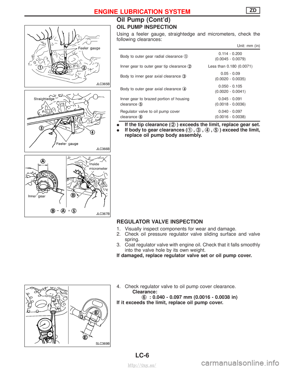
OIL PUMP INSPECTION
Using a feeler gauge, straightedge and micrometers, check the
following clearances:
Unit: mm (in)
Body to outer gear radial clearanceq10.114 - 0.200
(0.0045 - 0.0079)
Inner gear to outer gear tip clearance q
2Less than 0.180 (0.0071)
Body to inner gear axial clearance q
30.05 - 0.09
(0.0020 - 0.0035)
Body to outer gear axial clearance q
40.050 - 0.105
(0.0020 - 0.0041)
Inner gear to brazed portion of housing
clearance q
5
0.045 - 0.091
(0.0018 - 0.0036)
Regulator valve to oil pump cover
clearance q
6
0.040 - 0.097
(0.0016 - 0.0038)
I If the tip clearance ( q2) exceeds the limit, replace gear set.
I If body to gear clearances ( q
1,q3,q4,q5) exceed the limit,
replace oil pump body assembly.
REGULATOR VALVE INSPECTION
1. Visually inspect components for wear and damage.
2. Check oil pressure regulator valve sliding surface and valve spring.
3. Coat regulator valve with engine oil. Check that it falls smoothly into the valve hole by its own weight.
If damaged, replace regulator valve set or oil pump cover.
4. Check regulator valve to oil pump cover clearance. Clearance:q
6: 0.040 - 0.097 mm (0.0016 - 0.0038 in)
If it exceeds the limit, replace oil pump cover.
JLC365B
JLC366B
JLC367B
SLC369B
ENGINE LUBRICATION SYSTEMZD
Oil Pump (Cont'd)
LC-6
http://vnx.su/