Page 1005 of 1833
2. Adjust reverse clutch drum end play.
a. Install oil pump thrust washer on clutch pack.
b. Measure distance ªFº between front end of transmission caseand oil pump thrust washer.
c. Measure distance ªGº between front end of transmission case and gasket.
d. Determine dimension ªEº by using the following equation. E=FþG
e. Measure distance ªHº.
SAT212B
SAT213B
SAT214B
SAT215B
ASSEMBLY
Adjustment (Cont'd)
AT-192
http://vnx.su/
Page 1006 of 1833
f. Determine reverse clutch drum end play ªT2º by using the fol-
lowing equation. T
2=EþHþ0.1
Reverse clutch drum end play ªT
2º:
0.55 - 0.90 mm (0.0217 - 0.0354 in)
I If end play is out of specification, decrease or increase thick-
ness of oil pump thrust washer as necessary.
Available oil pump thrust washer: Refer to SDS, AT-204.
Assembly (2)
1. Install brake band and band strut.
a. Install band strut on brake band.
IApply petroleum jelly to band strut.
b. Place brake band on periphery of reverse clutch drum, and insert band strut into end of band servo piston stem.
c. Install anchor end bolt on transmission case. Then, tighten anchor end bolt just enough so that reverse clutch drum (clutch
pack) will not tilt forward.
2. Install input shaft on transmission case.
I Pay attention to its direction Ð O-ring groove side is front.
3. Install gasket on transmission case.
SAT980A
SAT985A
SAT986A
SAT987A
SAT988A
ASSEMBLY
Adjustment (Cont'd)
AT-193
http://vnx.su/
Page 1007 of 1833
4. Install oil pump assembly.
a. Install needle bearing on oil pump assembly.
IApply petroleum jelly to the needle bearing.
b. Install selected thrust washer on oil pump assembly.
I Apply petroleum jelly to thrust washer.
c. Carefully install seal rings into grooves and press them into the petroleum jelly so that they are a tight fit.
d. Install O-ring on oil pump assembly.
I Apply petroleum jelly to O-ring.
e. Apply petroleum jelly to mating surface of transmission case and oil pump assembly.
f. Install oil pump assembly.
I Install two converter housing securing bolts in bolt holes
in oil pump assembly as guides.
SAT989A
SAT990A
SAT991A
SAT992A
SAT993A
ASSEMBLY
Assembly (2) (Cont'd)
AT-194
http://vnx.su/
Page 1008 of 1833
IInsert oil pump assembly to the specified position in
transmission, as shown at left.
5. Install O-ring on input shaft.
I Apply ATF to O-rings.
6. Install converter housing.
a. Apply recommended sealant (Nissan genuine part: KP610- 00250 or equivalent) to outer periphery of bolt holes in con-
verter housing.
I Do not apply too much sealant.
b. Apply recommended sealant (Nissan genuine part: KP610- 00250 or equivalent) to seating surfaces of bolts that secure
front of converter housing.
c. Install converter housing on transmission case.
7. Adjust brake band.
a. Tighten anchor end bolt to specified torque. Anchor end bolt:
:4-6N ×m
(0.4 - 0.6 kg-m, 35 - 52 in-lb)
b. Back off anchor end bolt two and a half turns.
SAT994A
SAT114B
SAT397C
SAT158G
SAT001B
ASSEMBLY
Assembly (2) (Cont'd)
AT-195
http://vnx.su/
Page 1010 of 1833
e. Install control valve assembly on transmission case.
f. Install connector tube brackets and tighten boltsq
AandqB.
I Check that terminal assembly does not catch.
Bolt symbol mm (in)
qA33 (1.30)
q
B45 (1.77)
g. Install O-ring on oil strainer.
I Apply petroleum jelly to O-ring.
h. Install oil strainer on control valve.
i. Securely fasten terminal harness with clips.
j. Install torque converter clutch solenoid valve and fluid tempera- ture sensor connectors.
SAT353B
SAT221B
SAT009B
SAT010B
ASSEMBLY
Assembly (2) (Cont'd)
AT-197
http://vnx.su/
Page 1011 of 1833

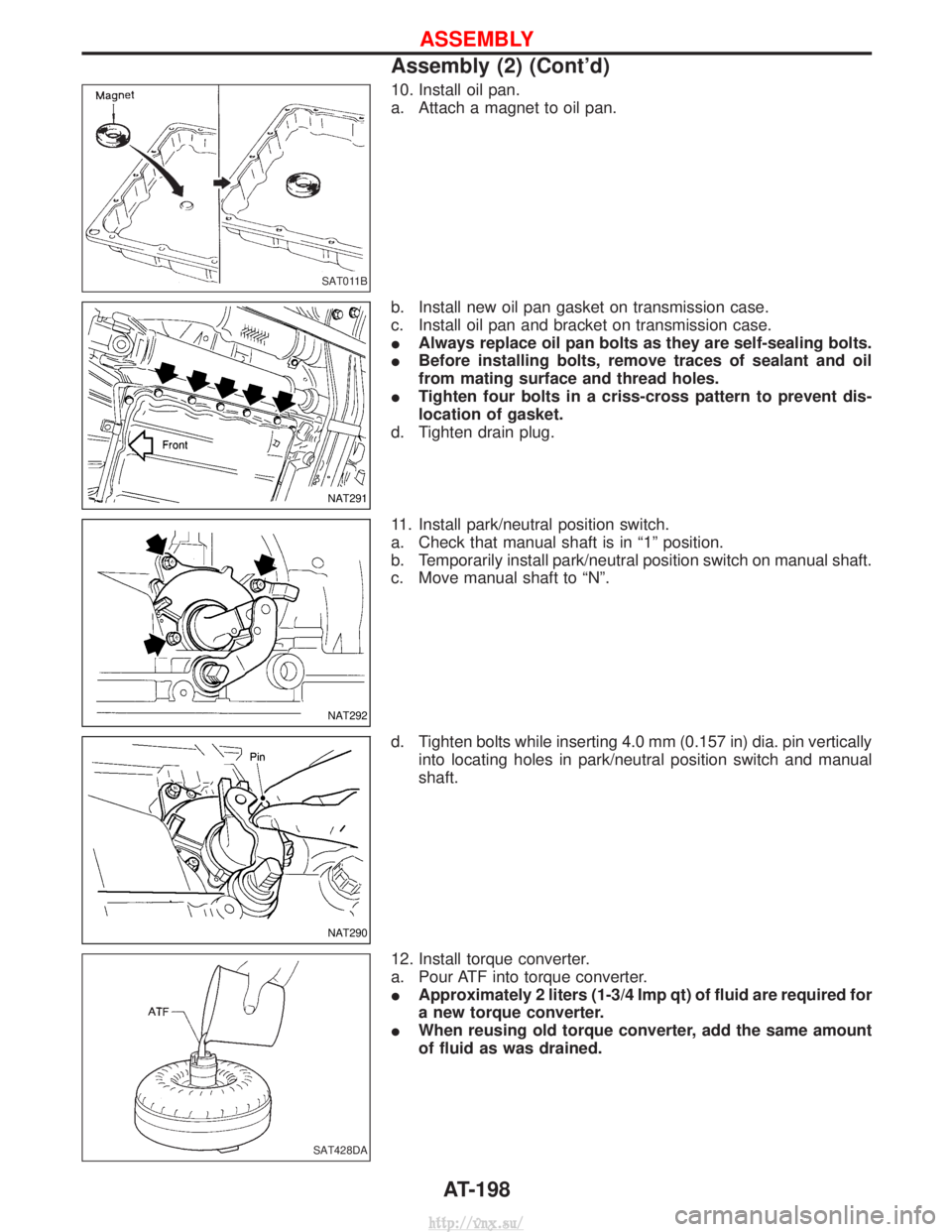
10. Install oil pan.
a. Attach a magnet to oil pan.
b. Install new oil pan gasket on transmission case.
c. Install oil pan and bracket on transmission case.
IAlways replace oil pan bolts as they are self-sealing bolts.
I Before installing bolts, remove traces of sealant and oil
from mating surface and thread holes.
I Tighten four bolts in a criss-cross pattern to prevent dis-
location of gasket.
d. Tighten drain plug.
11. Install park/neutral position switch.
a. Check that manual shaft is in ª1º position.
b. Temporarily install park/neutral position switch on manual shaft.
c. Move manual shaft to ªNº.
d. Tighten bolts while inserting 4.0 mm (0.157 in) dia. pin vertically into locating holes in park/neutral position switch and manual
shaft.
12. Install torque converter.
a. Pour ATF into torque converter.
I Approximately 2 liters (1-3/4 Imp qt) of fluid are required for
a new torque converter.
I When reusing old torque converter, add the same amount
of fluid as was drained.
SAT011B
NAT291
NAT292
NAT290
SAT428DA
ASSEMBLY
Assembly (2) (Cont'd)
AT-198
http://vnx.su/
Page 1024 of 1833
Removal
IDrain oil from transfer and transmission.
I Remove front and rear propeller shafts Ð Refer to PD section.
I Insert plug into oil seal after removing propeller shaft.
CAUTION:
Be careful not to damage spline, sleeve yoke and rear oil seal,
when removing propeller shaft.
I Remove torsion bar spring Ð Refer to removal and installation
of lower link in FA section. Then remove fifth crossmember.
I Remove transfer control lever from transfer outer shift lever.
I Remove transfer from transmission.
WARNING:
Support transfer while removing it.
Installation
I Apply recommended sealant to mating surface to transmission.
Recommended sealant: Nissan genuine part (KP610-00250) or equivalent
I Tighten bolts securing transfer.
Bolt No. Tightening torque
N×m (kg-m, ft-lb)
mm (in)
q
127 - 36 (2.8 - 3.6, 20 - 26) 45 (1.77)
q
227 - 36 (2.8 - 3.6, 20 - 26) 60 (2.36)
SMT478A
YTF001
SMT495A
SMT496A
REMOVAL AND INSTALLATION
TF-7
http://vnx.su/
Page 1064 of 1833
Removal
IRemove propeller shaft.
Insert plug into transfer or transmission after removing pro-
peller shaft.
I Remove axle shaft. Refer to RA section.
CAUTION:
I Be careful not to damage spline, sleeve yoke and front oil
seal when removing propeller shaft.
Installation
IFill final drive with recommended gear oil.
SPD123
REMOVAL AND INSTALLATION (Rear final drive Ð C200)
PD-13
http://vnx.su/