Page 857 of 1833

FON vehicleEFOFF vehicleE
Reference page (AT- )27,
120 11 9 56,
62,
82 30
65,
144 68,
86 71,
74 78,
11 8 11 8 11 8 71,
128 156,
160 162162,
170 166,
176 180
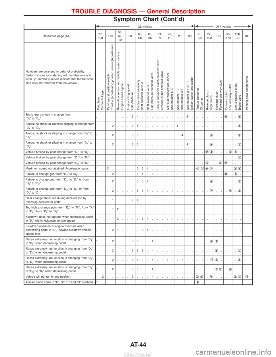
Numbers are arranged in order of probability.
Perform inspections starting with number one and
work up. Circled numbers indicate that the transmis-
sion must be removed from the vehicle.
Fluid level
Control linkage
Park/neutral position switch
Throttle (accelerator) position sensor (Adjustment)
Revolution sensor and vehicle speed sensor
Engine speed signal
Engine idling speed
Line pressure
Control valve assembly
Shift solenoid valve A
Shift solenoid valve B
Line pressure solenoid valve
Torque converter clutch solenoid valve
Overrun clutch solenoid valve
A/T fluid temperature sensor
Accumulator N-D
Accumulator 1-2
Accumulator 2-3
Accumulator 3-4 (N-R)
Ignition switch and starter
Torque converter
Oil pump
Reverse clutch
High clutch
Forward clutch
Forward one-way clutch
Overrun clutch
Low one-way clutch
Low & reverse brake
Brake band
Parking pawl components
Too sharp a shock in change from
ªD3ºtoªD4º. . ..1...24.........3. .
.....q6..q5.
Almost no shock or clutches slipping in change from
ªD
1ºtoªD2º. 1 ..2...35.......4... .
........q6.
Almost no shock or slipping in change from ªD
2ºto
ªD3º. 1 ..2...35........4.. ...
q6.....q7.
Almost no shock or slipping in change from ªD
3ºto
ªD4º. 1 ..2...35.........4. ...
q6.....q7.
Vehicle braked by gear change from ªD
1ºtoªD2º. 1 ................... .. q2q4...q5q3..
Vehicle braked by gear change from ªD
2ºtoªD3º. 1 ................... . ........q2.
Vehicle braked by gear change from ªD
3ºtoªD4º. 1 ................... .. q4..q3q2... .
Maximum speed not attained. Acceleration poor. 1 . 2 .....534.........q
11q10q6q7....q9q8.
Failure to change gear from ªD
4ºtoªD3º. 1 ..2....64.5.3...... . .....q8.q7..
Failure to change gear from ªD
3ºtoªD2º or from
ªD4ºtoªD2º. 1 ..2....534......... ...
q6.....q7.
Failure to change gear from ªD
2ºtoªD1º or from
ªD3ºtoªD1º. 1 ..2....534......... ...
q7...q6.q8.
Gear change shock felt during deceleration by
releasing accelerator pedal. . ..1...24....3...... .
......... .
Too high a change point from ªD
4ºtoªD3º, from ªD3º
to ªD2º, from ªD2ºtoªD1º. . ..12............... .
......... .
Kickdown does not operate when depressing pedal
in ªD
4º within kickdown vehicle speed. . ..12....34......... .
......... .
Kickdown operates or engine overruns when
depressing pedal in ªD
4º beyond kickdown vehicle
speed limit. . ..21....34......... .
......... .
Races extremely fast or slips in changing from ªD
4º
to ªD3º when depressing pedal. 1 ..2...35..4........ ...
q6q7..... .
Races extremely fast or slips in changing from ªD
4º
to ªD2º when depressing pedal. 1 ..2...365.4........ ....
q8....q7.
Races extremely fast or slips in changing from ªD
3º
to ªD2º when depressing pedal. 1 ..2...35..4..6..7.. ...
q10q9....q8.
Races extremely fast or slips in changing from ªD
4º
or ªD3ºtoªD1º when depressing pedal. 1 ..2...35..4........ ....
q6q7.q8.. .
Vehicle will not run in any position. 1 2 .....3...4........ q
9q5.q6.... q8q7q10
Transmission noise in ªDº, ª2º, ª1º and ªRº positions. 1
................... q2......... .
TROUBLE DIAGNOSIS Ð General Description
Symptom Chart (Cont'd)
AT-44
http://vnx.su/
Page 858 of 1833

FON vehicleEFOFF vehicleE
Reference page (AT- )27,
120 11 9 56,
62,
82 30
65,
144 68,
86 71,
74 78,
11 8 11 8 11 8 144,
128 156,
160 162162,
170 166,
176 180
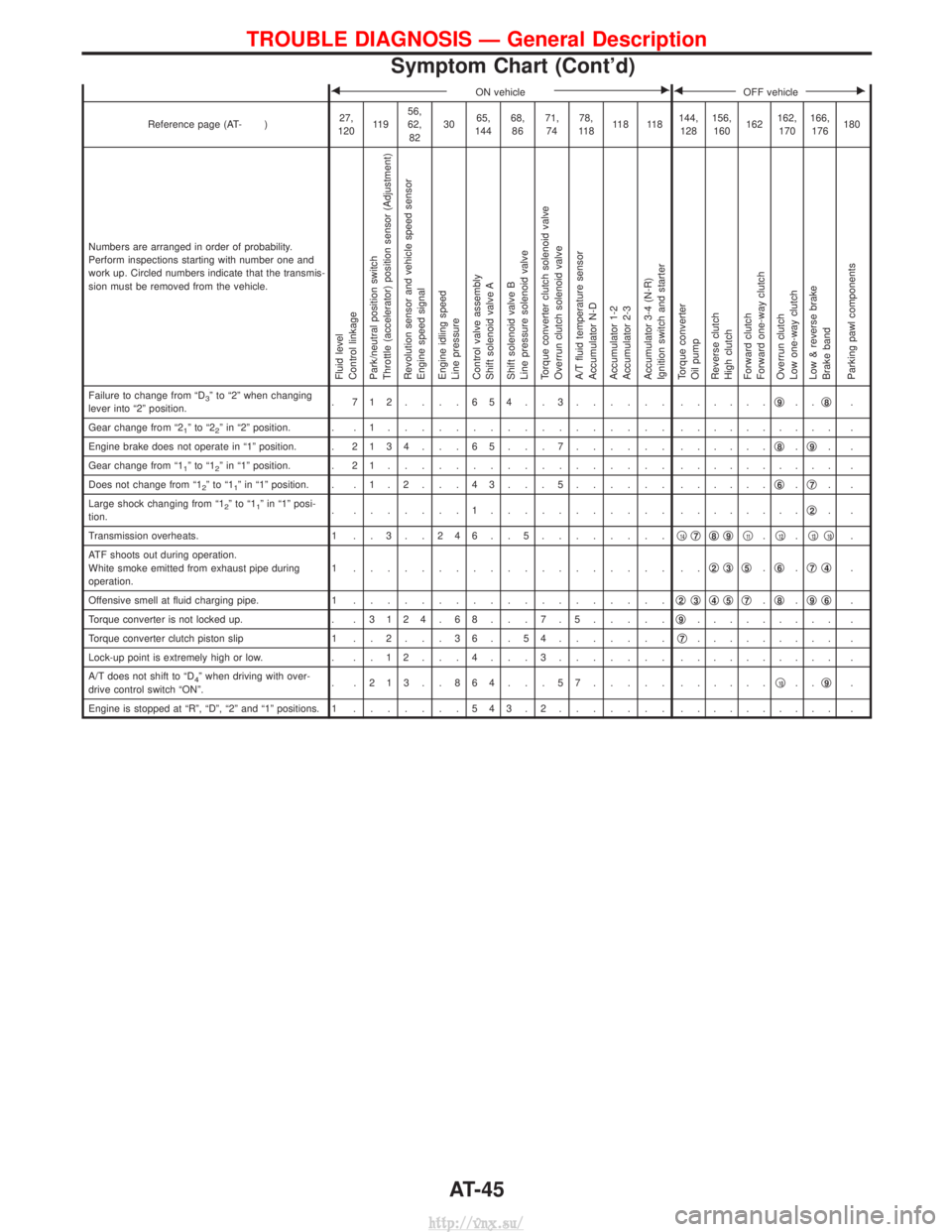
Numbers are arranged in order of probability.
Perform inspections starting with number one and
work up. Circled numbers indicate that the transmis-
sion must be removed from the vehicle.
Fluid level
Control linkage
Park/neutral position switch
Throttle (accelerator) position sensor (Adjustment)
Revolution sensor and vehicle speed sensor
Engine speed signal
Engine idling speed
Line pressure
Control valve assembly
Shift solenoid valve A
Shift solenoid valve B
Line pressure solenoid valve
Torque converter clutch solenoid valve
Overrun clutch solenoid valve
A/T fluid temperature sensor
Accumulator N-D
Accumulator 1-2
Accumulator 2-3
Accumulator 3-4 (N-R)
Ignition switch and starter
Torque converter
Oil pump
Reverse clutch
High clutch
Forward clutch
Forward one-way clutch
Overrun clutch
Low one-way clutch
Low & reverse brake
Brake band
Parking pawl components
Failure to change from ªD3º to ª2º when changing
lever into ª2º position. . 712....654..3...... .
.....q9..q8.
Gear change from ª2
1ºtoª22º in ª2º position. . . 1 ................. . ......... .
Engine brake does not operate in ª1º position. . 2134 . . . 65 . . . 7...... ......q
8.q9..
Gear change from ª1
1ºtoª12º in ª1º position. . 2 1 ................. . ......... .
Does not change from ª1
2ºtoª11º in ª1º position. . . 1 . 2 . . . 4 3 . . . 5 ...... ......q6.q7..
Large shock changing from ª1
2ºtoª11º in ª1º posi-
tion. . .......1........... .
.......q2..
Transmission overheats. 1 . . 3 . . 2 4 6 . . 5 ........q
14q7q8q9q11.q12.q13q10.
ATF shoots out during operation.
White smoke emitted from exhaust pipe during
operation. 1 ................... ..
q
2q3q5.q6.q7q4.
Offensive smell at fluid charging pipe. 1 ................... q
2q3q4q5q7.q8.q9q6.
Torque converter is not locked up. . . 3124 . 68 . . . 7 . 5.....q
9......... .
Torque converter clutch piston slip 1 . . 2 . . . 3 6 . . 5 4 .......q
7......... .
Lock-up point is extremely high or low. . . . 1 2 . . . 4 . . . 3 ....... .......... .
A/T does not shift to ªD
4º when driving with over-
drive control switch ªONº. . .213..864...57..... .
.....q10..q9.
Engine is stopped at ªRº, ªDº, ª2º and ª1º positions. 1 .......543.2....... . ......... .
TROUBLE DIAGNOSIS Ð General Description
Symptom Chart (Cont'd)
AT-45
http://vnx.su/
Page 932 of 1833

Revolution Sensor Replacement
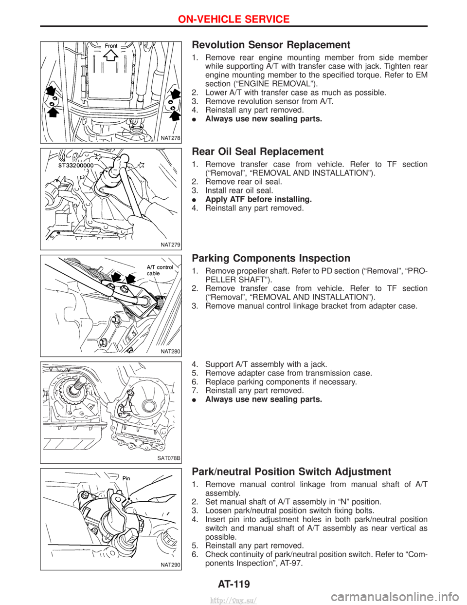
1. Remove rear engine mounting member from side memberwhile supporting A/T with transfer case with jack. Tighten rear
engine mounting member to the specified torque. Refer to EM
section (ªENGINE REMOVALº).
2. Lower A/T with transfer case as much as possible.
3. Remove revolution sensor from A/T.
4. Reinstall any part removed.
I Always use new sealing parts.
Rear Oil Seal Replacement
1. Remove transfer case from vehicle. Refer to TF section
(ªRemovalº, ªREMOVAL AND INSTALLATIONº).
2. Remove rear oil seal.
3. Install rear oil seal.
I Apply ATF before installing.
4. Reinstall any part removed.
Parking Components Inspection
1. Remove propeller shaft. Refer to PD section (ªRemovalº, ªPRO- PELLER SHAFTº).
2. Remove transfer case from vehicle. Refer to TF section (ªRemovalº, ªREMOVAL AND INSTALLATIONº).
3. Remove manual control linkage bracket from adapter case.
4. Support A/T assembly with a jack.
5. Remove adapter case from transmission case.
6. Replace parking components if necessary.
7. Reinstall any part removed.
I Always use new sealing parts.
Park/neutral Position Switch Adjustment
1. Remove manual control linkage from manual shaft of A/T
assembly.
2. Set manual shaft of A/T assembly in ªNº position.
3. Loosen park/neutral position switch fixing bolts.
4. Insert pin into adjustment holes in both park/neutral position switch and manual shaft of A/T assembly as near vertical as
possible.
5. Reinstall any part removed.
6. Check continuity of park/neutral position switch. Refer to ªCom- ponents Inspectionº, AT-97.
NAT278
NAT279
NAT280
SAT078B
NAT290
ON-VEHICLE SERVICE
AT-119
http://vnx.su/
Page 941 of 1833
Disassembly
1. Drain ATF through drain plug.
2. Remove torque converter by holding it firmly and turning whilepulling straight out.
3. Check torque converter one-way clutch.
a. Insert Tool into spline of one-way clutch inner race.
b. Hook bearing support unitized with one-way clutch outer race with suitable wire.
c. Check that one-way clutch inner race rotates only clockwise with Tool while holding bearing support with wire.
4. Remove park/neutral position switch from transmission case.
5. Remove oil pan.
I Always place oil pan straight down so that foreign par-
ticles inside will not move.
6. Place transmission into Tool with the control valve facing up.
SAT018B
NAT226
YAT339
SAT754I
NAT227
DISASSEMBLY
AT-128
http://vnx.su/
Page 944 of 1833
12. Remove converter housing from transmission case.
IBe careful not to scratch converter housing.
13. Remove O-ring from input shaft.
14. Remove oil pump assembly.
a. Attach Tool to oil pump assembly and extract it evenly from transmission case.
b. Remove O-ring from oil pump assembly.
c. Remove traces of sealant from oil pump housing.
I Be careful not to scratch pump housing.
d. Remove needle bearing and thrust washer from oil pump assembly.
SAT999A
SAT995A
NAT229
SAT028B
SAT108B
DISASSEMBLY
Disassembly (Cont'd)
AT-131
http://vnx.su/
Page 945 of 1833
15. Remove input shaft and oil pump gasket.
16. Remove brake band and band strut.
a. Loosen lock nut and remove band servo anchor end pin fromtransmission case.
b. Remove brake band and band strut from transmission case.
c. Hold brake band in a circular shape with clip.
17. Remove front side clutch and gear components.
a. Remove clutch pack (reverse clutch, high clutch and front sun gear) from transmission case.
SAT988A
SAT029B
SAT986A
SAT655
SAT030B
DISASSEMBLY
Disassembly (Cont'd)
AT-132
http://vnx.su/
Page 949 of 1833
e. Remove needle bearing from overrun clutch hub.
f. Remove overrun clutch hub from rear internal gear and forwardclutch hub.
g. Remove thrust washer from overrun clutch hub.
h. Remove forward clutch assembly from transmission case.
21. Remove band servo and accumulator components.
a. Remove band servo retainer from transmission case.
b. Apply compressed air to oil hole until band servo piston comes out of transmission case.
I Hold piston with a rag and gradually direct air to oil hole.
c. Remove return springs.
SAT148G
SAT036B
SAT037B
SAT038B
SAT039B
DISASSEMBLY
Disassembly (Cont'd)
AT-136
http://vnx.su/
Page 950 of 1833
d. Remove springs from accumulator pistonsqB,qCand qD.
e. Apply compressed air to each oil hole until piston comes out.
I Hold piston with a rag and gradually direct air to oil hole.
Identification of accumulator pistons qAqBqCqD
Identification of oil holes qaqbqcqd
f. Remove O-ring from each piston.
22. Remove manual shaft components, if necessary.
a. Hold width across flats of manual shaft (outside the transmis-
sion case) and remove lock nut from shaft.
b. Remove retaining pin from transmission case.
c. While pushing detent spring down, remove manual plate and parking rod from transmission case.
SAT040BA
SAT523GA
SAT041B
SAT042B
SAT935A
DISASSEMBLY
Disassembly (Cont'd)
AT-137
http://vnx.su/