Page 741 of 1833

Diagnostic Procedure
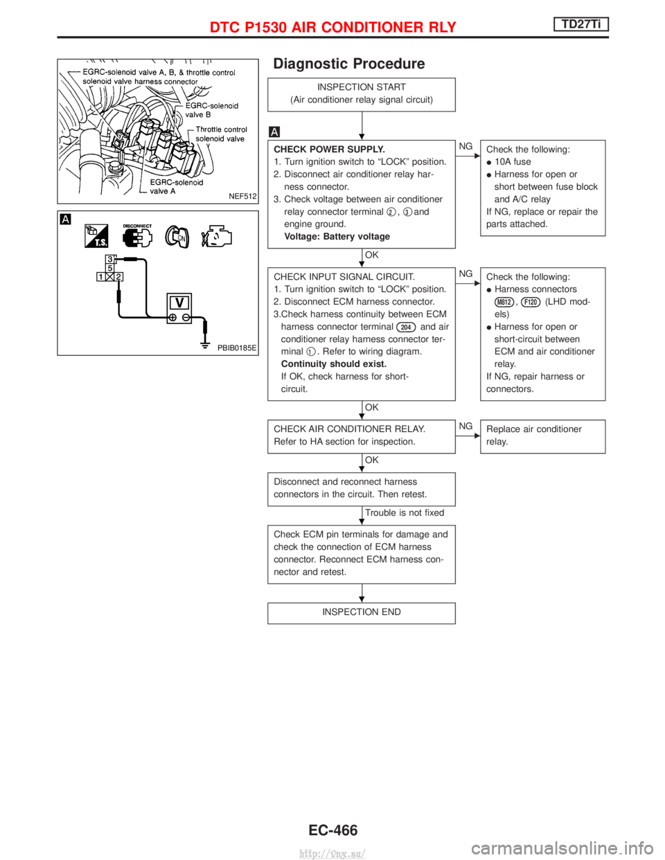
INSPECTION START
(Air conditioner relay signal circuit)
CHECK POWER SUPPLY.
1. Turn ignition switch to ªLOCKº position.
2. Disconnect air conditioner relay har- ness connector.
3. Check voltage between air conditioner relay connector terminal q
2,q3and
engine ground.
Voltage: Battery voltage
OK
ENG Check the following:
I10A fuse
I Harness for open or
short between fuse block
and A/C relay
If NG, replace or repair the
parts attached.
CHECK INPUT SIGNAL CIRCUIT.
1. Turn ignition switch to ªLOCKº position.
2. Disconnect ECM harness connector.
3.Check harness continuity between ECM harness connector terminal
204and air
conditioner relay harness connector ter-
minal q
1. Refer to wiring diagram.
Continuity should exist.
If OK, check harness for short-
circuit.
OK
ENG Check the following:
IHarness connectors
M812,F120(LHD mod-
els)
I Harness for open or
short-circuit between
ECM and air conditioner
relay.
If NG, repair harness or
connectors.
CHECK AIR CONDITIONER RELAY.
Refer to HA section for inspection.
OK
ENG Replace air conditioner
relay.
Disconnect and reconnect harness
connectors in the circuit. Then retest.
Trouble is not fixed
Check ECM pin terminals for damage and
check the connection of ECM harness
connector. Reconnect ECM harness con-
nector and retest.
INSPECTION END
NEF512
PBIB0185E
H
H
H
H
H
H
DTC P1530 AIR CONDITIONER RLYTD27Ti
EC-466
http://vnx.su/
Page 746 of 1833

Diagnostic Procedure
INSPECTION START
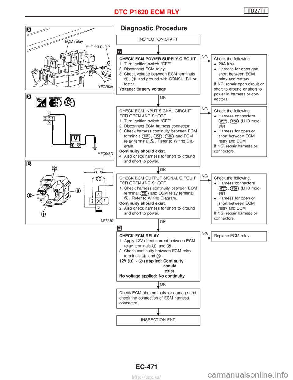
CHECK ECM POWER SUPPLY CIRCUIT.
1. Turn ignition switch ªOFFº.
2. Disconnect ECM relay.
3. Check voltage between ECM terminals q
1,q3and ground with CONSULT-II or
tester.
Voltage: Battery voltage
OK
ENG Check the following.
I20A fuse
I Harness for open and
short between ECM
relay and battery
If NG, repair open circuit or
short to ground or short to
power in harness or con-
nectors.
CHECK ECM INPUT SIGNAL CIRCUIT
FOR OPEN AND SHORT
1. Turn ignition switch ªOFFº.
2. Disconnect ECM harness connector.
3. Check harness continuity between ECM terminals
107,108,109and ECM
relay terminal q
5. Refer to Wiring Dia-
gram.
Continuity should exist.
4. Also check harness for short to ground and short to power.
OK
ENG Check the following.
IHarness connectors
M787,F66(LHD mod-
els)
I Harness for open or
short between ECM
relay and ECM
If NG, repair harness or
connectors.
CHECK ECM OUTPUT SIGNAL CIRCUIT
FOR OPEN AND SHORT.
1. Check harness continuity between ECM terminal
325and ECM relay terminal
q
2. Refer to Wiring Diagram.
Continuity should exist.
2. Also check harness for short to ground and short to power.
OK
ENG Check the following.
IHarness connectors
M787,F66(LHD mod-
els)
I Harness for open or
short between ECM
relay and ECM
If NG, repair harness or
connectors.
CHECK ECM RELAY
1. Apply 12V direct current between ECM relay terminals q
1andq2.
2. Check continuity between ECM relay terminals q
3andq5.
12V ( q
1-q2) applied: Continuity
shouldexist
No voltage applied: No continuity
OK
ENG Replace ECM relay.
Check ECM pin terminals for damage and
check the connection of ECM harness
connector.
INSPECTION END
YEC283A
MEC945D
NEF350
H
H
H
H
H
H
DTC P1620 ECM RLYTD27Ti
EC-471
http://vnx.su/
Page 863 of 1833
TCM Power Supply Circuit
DIAGNOSTIC PROCEDURE
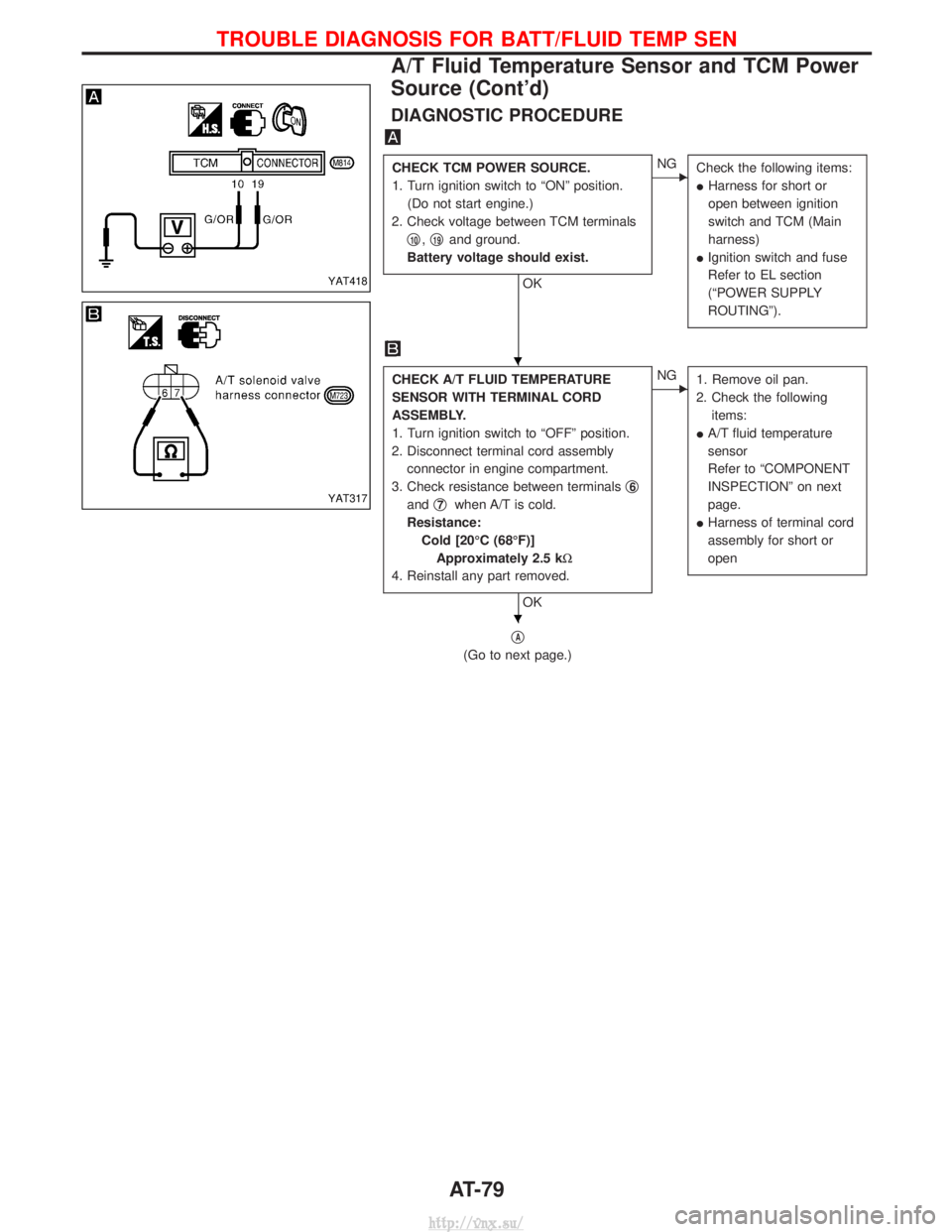
CHECK TCM POWER SOURCE.
1. Turn ignition switch to ªONº position.(Do not start engine.)
2. Check voltage between TCM terminals q
10,q19and ground.
Battery voltage should exist.
OK
ENG Check the following items:
IHarness for short or
open between ignition
switch and TCM (Main
harness)
I Ignition switch and fuse
Refer to EL section
(ªPOWER SUPPLY
ROUTINGº).
CHECK TCM GROUND CIRCUIT.
1. Turn ignition switch to ªOFFº position.
2. Disconnect TCM harness connector.
3. Check resistance between TCM termi- nals q
25,q48and ground.
Resistance: Approximately 0W
If OK, check harness for short to
ground and short to power.
OK
ENG Repair open circuit or short
to ground or short to
power in harness or con-
nector.
INSPECTION END
YAT427
YAT428
H
H
TROUBLE DIAGNOSIS FOR POWER SUPPLY
AT-50
http://vnx.su/
Page 892 of 1833

DIAGNOSTIC PROCEDURE
CHECK TCM POWER SOURCE.
1. Turn ignition switch to ªONº position.(Do not start engine.)
2. Check voltage between TCM terminals q
10,q19and ground.
Battery voltage should exist.
OK
ENG Check the following items:
IHarness for short or
open between ignition
switch and TCM (Main
harness)
I Ignition switch and fuse
Refer to EL section
(ªPOWER SUPPLY
ROUTINGº).
CHECK A/T FLUID TEMPERATURE
SENSOR WITH TERMINAL CORD
ASSEMBLY.
1. Turn ignition switch to ªOFFº position.
2. Disconnect terminal cord assembly connector in engine compartment.
3. Check resistance between terminals q
6
andq7when A/T is cold.
Resistance: Cold [20ÉC (68ÉF)]Approximately 2.5 kW
4. Reinstall any part removed.
OK
ENG 1. Remove oil pan.
2. Check the following items:
I A/T fluid temperature
sensor
Refer to ªCOMPONENT
INSPECTIONº on next
page.
I Harness of terminal cord
assembly for short or
open
qA
(Go to next page.)
YAT418
YAT317
H
H
TROUBLE DIAGNOSIS FOR BATT/FLUID TEMP SEN
A/T Fluid Temperature Sensor and TCM Power
Source (Cont'd)
AT-79
http://vnx.su/
Page 912 of 1833

1. SPORT Indicator Lamp Does Not Come On
SYMPTOM:
POWER indicator lamp does not come on for about 2 seconds
when turning ignition switch to ªONº.
CHECK TCM POWER SOURCE.
1. Turn ignition switch to ªONº position.(Do not start engine.)
2. Check voltage between TCM terminals q
10,q19and ground.
Battery voltage should exist.
OK
ENG Check the following items:
IHarness for short or
open between ignition
switch and TCM (Main
harness)
I Ignition switch and fuse
Refer to EL section
(ªPOWER SUPPLY
ROUTINGº).
CHECK TCM GROUND CIRCUIT.
1. Turn ignition switch to ªOFFº position.
2. Disconnect TCM harness connector.
3. Check resistance between TCM termi- nals q
25,q48and ground.
Resistance: Approximately 0W
If OK, check harness for short to
ground and short to power.
OK
ENG Repair open circuit or short
to ground or short to
power in harness or con-
nector.
CHECK LAMP CIRCUIT.
1. Turn ignition switch to ªONº position.
2. Set overdrive control, A/T check or power switch to ªONº position.
3. Check voltage between TCM terminal q
13and ground.
Voltage: Battery voltage
4. Reinstall any part removed.
OK
ENG Check the following items:
IFuse (7.5A)
I SPORT indicator lamp
Refer to EL section
(ªWARNING LAMPSº).
I Harness for short or
open between ignition
switch and SPORT indi-
cator lamp (Main har-
ness)
Refer to EL section
(ªPOWER SUPPLY
ROUTINGº).
I Harness for short or
open between SPORT
indicator lamp and TCM
Check again.
OK
ENG
1. Perform TCM input/
output signal inspection.
2. If NG, recheck TCM pin terminals for damage or
loose connection with
harness connector.
INSPECTION END
YAT427
YAT428
YAT429
H
H
HH
H
DIAGNOSTIC PROCEDURES FOR SYMPTOMS
AT-99
http://vnx.su/
Page 1067 of 1833
2. Remove extension tube and differential side shaft assembly.
3. Remove differential side flange.
4. Mark side retainers for identification. Remove side retainers.
Be careful not to confuse right and left side retainers and
shims.
5. Extract differential case from final drive housing.
6. Remove side outer races.Tool number:ST33290001
Be careful to keep the side bearing outer races together with
their respective inner cones Ð do not mix them up.
7. Remove side oil seal.
NPD005
SPD713
SPD639
SPD309
PD243
DISASSEMBLY (R180A)
Final Drive Housing (Cont'd)
PD-16
http://vnx.su/
Page 1069 of 1833
Differential Case
1. Remove side bearing inner cones.
To prevent damage to bearing, engage puller jaws in grooves.Assembly:ST33065001
Tool number: q
AST33051001
q
BST33061000
Be careful not to confuse the right and left hand parts.
2. Loosen ring gear bolts in a criss-cross fashion.
3. Tap ring gear off differential case with a soft hammer.
Tap evenly all around to keep ring gear from binding.
4. Separate L.H. and R.H. differential cases.
Put match marks on both L.H. and R.H. differential cases.
SPD642
SPD022
SPD024
SPD643
DISASSEMBLY (R180A)
PD-18
http://vnx.su/
Page 1091 of 1833
11. Remove pinion rear bearing inner cone and drive pinion adjust-ing washer.Tool number: ST30031000
Differential Case
1. Remove side bearing inner cones.
To prevent damage to bearing, engage puller jaws in groove. Tool number:q
AST33051001
q
BST33061000
Be careful not to confuse left and right hand parts.
2. Loosen ring gear bolts in a criss-cross fashion.
3. Tap ring gear off differential case with a soft hammer.
Tap evenly all around to keep ring gear from binding.
SPD018
SPD688
SPD022
SPD024
DISASSEMBLY (C200)
Differential Carrier (Cont'd)
PD-40
http://vnx.su/