Page 357 of 1833
DIAGNOSTIC PROCEDURE
1 INSPECTION START
Start engine.
Is engine running?YesorNo
Ye s EGO TO 14.
No EGO TO 2.
2 CHECK ECM POWER SUPPLY CIRCUIT-I
1. Turn ignition switch ªONº.
2. Check voltage between ECM terminal 38 and ground with CONSULT-II or tester.
SEF397Y
OK or NG
OK EGO TO 4.
NG EGO TO 3.
3 DETECT MALFUNCTIONING PART
Check the following.
I10A fuse
I Harness for open or short between ECM and fuse
ERepair open circuit or short to ground or short to power in harness or connectors.
4 CHECK ECM GROUND CIRCUIT FOR OPEN AND SHORT
1. Turn ignition switch ªOFFº.
2. Disconnect ECM harness connector.
3. Check harness continuity between ECM terminals 39, 43, 106, 112, 118 and engine ground. Refer to Wiring Diagram.
Continuity should exist.
4. Also check harness for short to ground and short to power.
OK or NG
OK EGO TO 6.
NG EGO TO 5.
TROUBLE DIAGNOSIS FOR POWER SUPPLYZD30DDTi
Main Power Supply and Ground Circuit
(Cont'd)
EC-82
http://vnx.su/
Page 359 of 1833
7 CHECK ECM POWER SUPPLY CIRCUIT-III
1. Disconnect ECM relay.
MEC021E
2. Check voltage between relay terminals 2, 3 and ground with CONSULT-II or tester.
MEC978DVoltage: Battery VoltageOK or NG
OK EGO TO 9.
NG EGO TO 8.
8 DETECT MALFUNCTIONING PART
Check the following.
I10A fuse
I 15A fuse
I Harness for open or short between ECM relay and battery
ERepair open circuit or short to ground or short to power in harness or connectors.
9 CHECK OUTPUT SIGNAL CIRCUIT FOR OPEN AND SHORT
1. Disconnect ECM harness connector.
2. Check harness continuity between ECM terminal 4 and ECM relay terminal 1. Refer to Wiring Diagram.
Continuity should exist.
3. Also check harness for short to ground and short to power.
OK or NG
OK EGO TO 11.
NG EGO TO 10.
TROUBLE DIAGNOSIS FOR POWER SUPPLYZD30DDTi
Main Power Supply and Ground Circuit
(Cont'd)
EC-84
http://vnx.su/
Page 361 of 1833
14 CHECK ECM POWER SUPPLY CIRCUIT-V
1. Reconnect all harness connectors disconnected.
2. Turn ignition switch ªONº.
3. Check voltage between ECM terminal 102 and ground with CONSULT-II or tester.
SEF290Z
OK or NG
OK EGO TO 16.
NG EGO TO 15.
15 DETECT MALFUNCTIONING PART
Check the following.
I10A fuse
I Harness for open or short between ECM and fuse
ERepair open circuit or short to ground or short to power in harness or connectors.
16 CHECK ECM POWER SUPPLY CIRCUIT-VI
1. Turn ignition switch ªOFFº.
2. Disconnect ECM relay.
MEC021E
3. Disconnect ECM harness connector.
4. Check harness continuity between ECM terminals 56, 61, 116 and ECM relay terminal 5. Refer to Wiring Diagram.
Continuity should exist.
5. Also check harness for short to ground and short to power.
OK or NG
OK EGO TO 18.
NG EGO TO 17.
TROUBLE DIAGNOSIS FOR POWER SUPPLYZD30DDTi
Main Power Supply and Ground Circuit
(Cont'd)
EC-86
http://vnx.su/
Page 390 of 1833
4 CHECK COOLING FAN POWER SUPPLY CIRCUIT
1. Turn ignition switch ªOFFº.
2. Disconnect cooling fan relay.
MEC021E
3. Turn ignition switch ªONº.
4. Turn air conditioner switch ªONº.
5. Turn blower fan switch ªONº.
6. Check voltage between cooling fan relay terminals 2, 3 and ground with CONSULT-II or tester.
MEC974DVoltage: Battery voltageOK or NG
OK EGO TO 6.
NG EGO TO 5.
5 DETECT MALFUNCTIONING PART
Check the following.
I10A fuse
I Harness connector F120, M812 (LHD models)
I A/C relay
I 30A fusible link
I Harness for open or short between cooling fan relay and fuse
I Harness for open or short between cooling fan relay and battery
ERepair open circuit or short to ground or short to power in harness or connectors.
DTC 0208 OVER HEATZD30DDTi
Diagnostic Procedure (Cont'd)
EC-115
http://vnx.su/
Page 487 of 1833
3 DETECT MALFUNCTIONING PART
Check the following.
IFuse block (J/B) connector F114 (LHD models), M835 (RHD models)
I 15A fuse
I Harness for open and short between stop lamp switch and fuse
ERepair open circuit or short to ground or short to power in harness or connectors.
4 CHECK STOP LAMP SWITCH INPUT SIGNAL CIRCUIT FOR OPEN AND SHORT
1. Turn ignition switch ªOFFº.
2. Disconnect ECM harness connector.
3. Disconnect stop lamp switch harness connector.
MEC027E
4. Check harness continuity between ECM terminal 17 and stop lamp switch terminal 2. Refer to Wiring Diagram.
Continuity should exist.
5. Also check harness for short to ground and short to power.
OK or NG
OK EGO TO 5.
NG ERepair open circuit or short to ground or short to power in harness or connectors.
DTC 0807 ECM 14ZD30DDTi
Diagnostic Procedure (Cont'd)
EC-212
http://vnx.su/
Page 491 of 1833
Diagnostic Procedure
1 CHECK ECM POWER SUPPLY CIRCUIT
1. Turn ignition switch ªOFFº.
2. Disconnect ECM relay.
MEC021E
3. Check voltage between ECM relay terminals 2, 3 and ground with CONSULT-II or tester.
MEC978DVoltage: Battery voltageOK or NG
OK EGO TO 3.
NG EGO TO 2.
2 DETECT MALFUNCTIONING PART
Check the following.
I10A fuse
I 15A fuse
I Harness for open and short between ECM relay and battery
ERepair open circuit or short to ground or short to power in harness or connectors.
3 CHECK ECM INPUT SIGNAL CIRCUIT FOR OPEN AND SHORT
1. Turn ignition switch ªOFFº.
2. Disconnect ECM harness connector.
3. Check harness continuity between ECM terminals 56, 61, 116 and ECM relay terminal 5. Refer to Wiring Diagram.
Continuity should exist.
4. Also check harness for short to ground and short to power.
OK or NG
OK EGO TO 5.
NG EGO TO 4.
DTC 0902 ECM RLYZD30DDTi
EC-216
http://vnx.su/
Page 508 of 1833

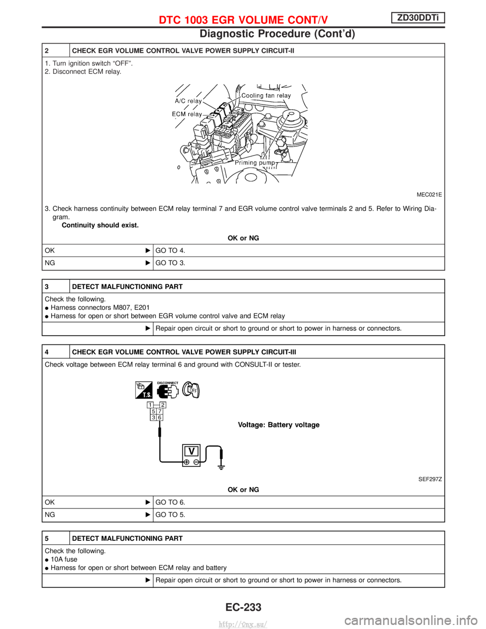
2 CHECK EGR VOLUME CONTROL VALVE POWER SUPPLY CIRCUIT-II
1. Turn ignition switch ªOFFº.
2. Disconnect ECM relay.
MEC021E
3. Check harness continuity between ECM relay terminal 7 and EGR volume control valve terminals 2 and 5. Refer to Wiring Dia-gram. Continuity should exist.
OK or NG
OK EGO TO 4.
NG EGO TO 3.
3 DETECT MALFUNCTIONING PART
Check the following.
IHarness connectors M807, E201
I Harness for open or short between EGR volume control valve and ECM relay
ERepair open circuit or short to ground or short to power in harness or connectors.
4 CHECK EGR VOLUME CONTROL VALVE POWER SUPPLY CIRCUIT-III
Check voltage between ECM relay terminal 6 and ground with CONSULT-II or tester.
SEF297Z
OK or NG
OK EGO TO 6.
NG EGO TO 5.
5 DETECT MALFUNCTIONING PART
Check the following.
I10A fuse
I Harness for open or short between ECM relay and battery
ERepair open circuit or short to ground or short to power in harness or connectors.
DTC 1003 EGR VOLUME CONT/VZD30DDTi
Diagnostic Procedure (Cont'd)
EC-233
http://vnx.su/
Page 524 of 1833

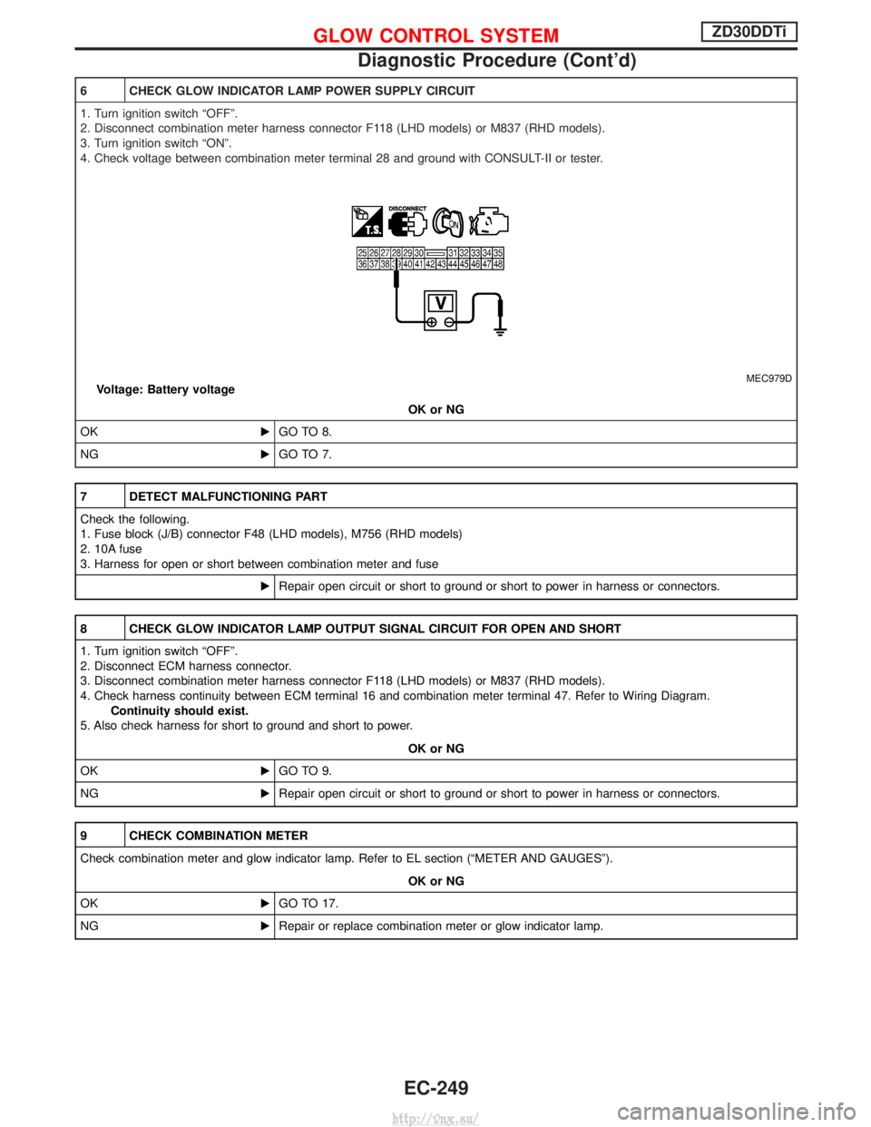
6 CHECK GLOW INDICATOR LAMP POWER SUPPLY CIRCUIT
1. Turn ignition switch ªOFFº.
2. Disconnect combination meter harness connector F118 (LHD models) or M837 (RHD models).
3. Turn ignition switch ªONº.
4. Check voltage between combination meter terminal 28 and ground with CONSULT-II or tester.
MEC979DVoltage: Battery voltageOK or NG
OK EGO TO 8.
NG EGO TO 7.
7 DETECT MALFUNCTIONING PART
Check the following.
1. Fuse block (J/B) connector F48 (LHD models), M756 (RHD models)
2. 10A fuse
3. Harness for open or short between combination meter and fuse
ERepair open circuit or short to ground or short to power in harness or connectors.
8 CHECK GLOW INDICATOR LAMP OUTPUT SIGNAL CIRCUIT FOR OPEN AND SHORT
1. Turn ignition switch ªOFFº.
2. Disconnect ECM harness connector.
3. Disconnect combination meter harness connector F118 (LHD models) or M837 (RHD models).
4. Check harness continuity between ECM terminal 16 and combination meter terminal 47. Refer to Wiring Diagram.
Continuity should exist.
5. Also check harness for short to ground and short to power.
OK or NG
OK EGO TO 9.
NG ERepair open circuit or short to ground or short to power in harness or connectors.
9 CHECK COMBINATION METER
Check combination meter and glow indicator lamp. Refer to EL section (ªMETER AND GAUGESº).
OK or NG
OK EGO TO 17.
NG ERepair or replace combination meter or glow indicator lamp.
GLOW CONTROL SYSTEMZD30DDTi
Diagnostic Procedure (Cont'd)
EC-249
http://vnx.su/